2021 RAM PROMASTER CITY key
[x] Cancel search: keyPage 37 of 280
GETTING TO KNOW YOUR VEHICLE35
WINDOWS
Power Window Controls — If Equipped
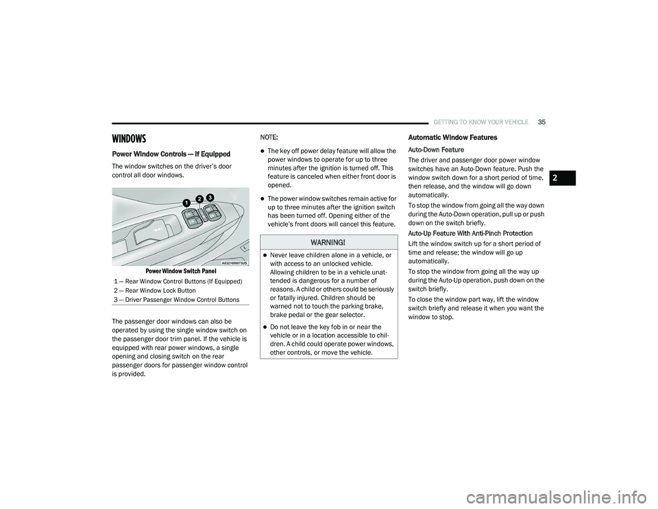
The window switches on the driver’s door
control all door windows.
Power Window Switch Panel
The passenger door windows can also be
operated by using the single window switch on
the passenger door trim panel. If the vehicle is
equipped with rear power windows, a single
opening and closing switch on the rear
passenger doors for passenger window control
is provided. NOTE:
The key off power delay feature will allow the
power windows to operate for up to three
minutes after the ignition is turned off. This
feature is canceled when either front door is
opened.
The power window switches remain active for
up to three minutes after the ignition switch
has been turned off. Opening either of the
vehicle’s front doors will cancel this feature.
Automatic Window Features
Auto-Down Feature
The driver and passenger door power window
switches have an Auto-Down feature. Push the
window switch down for a short period of time,
then release, and the window will go down
automatically.
To stop the window from going all the way down
during the Auto-Down operation, pull up or push
down on the switch briefly.
Auto-Up Feature With Anti-Pinch Protection
Lift the window switch up for a short period of
time and release; the window will go up
automatically.
To stop the window from going all the way up
during the Auto-Up operation, push down on the
switch briefly.
To close the window part way, lift the window
switch briefly and release it when you want the
window to stop.
1 — Rear Window Control Buttons (If Equipped)
2 — Rear Window Lock Button
3 — Driver Passenger Window Control Buttons
WARNING!
Never leave children alone in a vehicle, or
with access to an unlocked vehicle.
Allowing children to be in a vehicle unat
-
tended is dangerous for a number of
reasons. A child or others could be seriously
or fatally injured. Children should be
warned not to touch the parking brake,
brake pedal or the gear selector.
Do not leave the key fob in or near the
vehicle or in a location accessible to chil -
dren. A child could operate power windows,
other controls, or move the vehicle.
2
21_VM_OM_EN_USC_t.book Page 35
Page 41 of 280
GETTING TO KNOW YOUR VEHICLE39
NOTE:
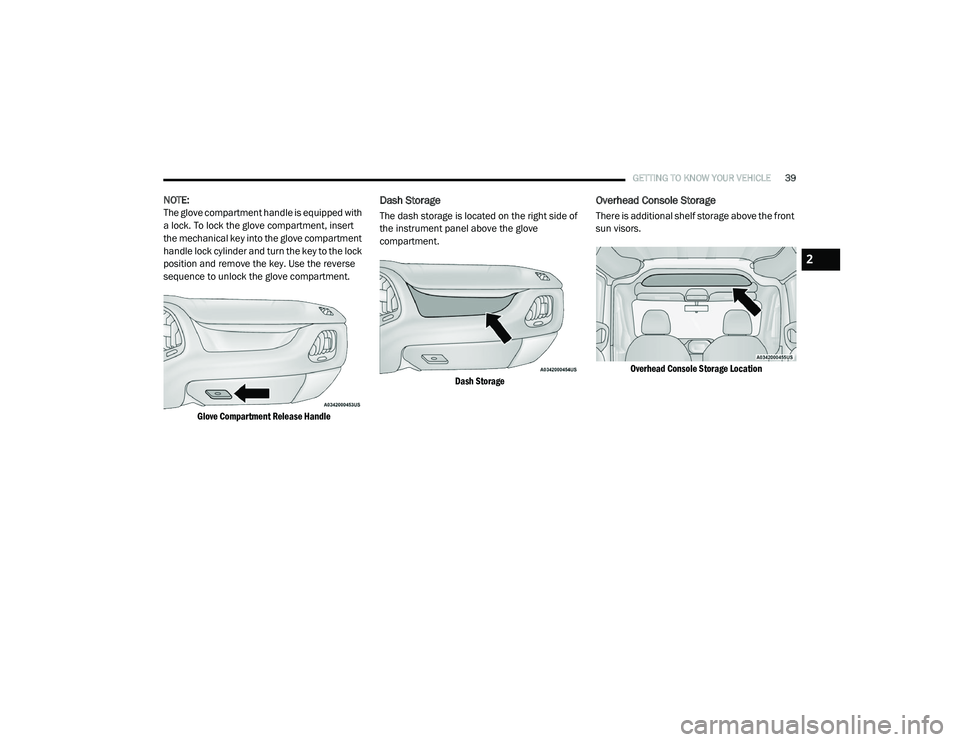
The glove compartment handle is equipped with
a lock. To lock the glove compartment, insert
the mechanical key into the glove compartment
handle lock cylinder and turn the key to the lock
position and remove the key. Use the reverse
sequence to unlock the glove compartment.
Glove Compartment Release Handle
Dash Storage
The dash storage is located on the right side of
the instrument panel above the glove
compartment.
Dash Storage
Overhead Console Storage
There is additional shelf storage above the front
sun visors.
Overhead Console Storage Location
2
21_VM_OM_EN_USC_t.book Page 39
Page 42 of 280
40GETTING TO KNOW YOUR VEHICLE
USB Control — If Equipped
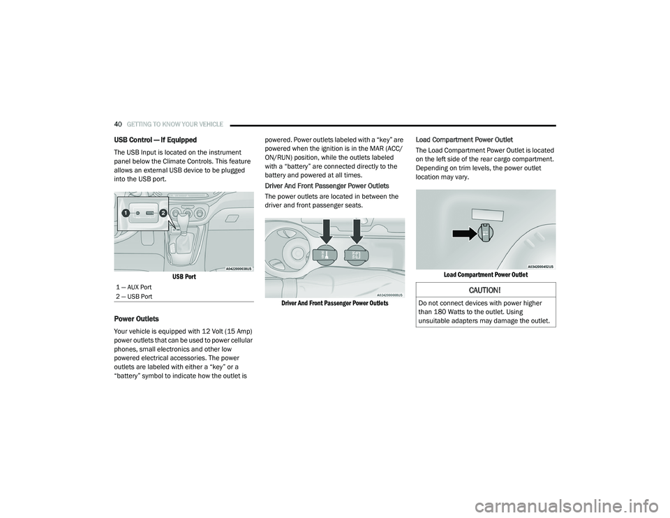
The USB Input is located on the instrument
panel below the Climate Controls. This feature
allows an external USB device to be plugged
into the USB port.
USB Port
Power Outlets
Your vehicle is equipped with 12 Volt (15 Amp)
power outlets that can be used to power cellular
phones, small electronics and other low
powered electrical accessories. The power
outlets are labeled with either a “key” or a
“battery” symbol to indicate how the outlet is powered. Power outlets labeled with a “key” are
powered when the ignition is in the MAR (ACC/
ON/RUN) position, while the outlets labeled
with a “battery” are connected directly to the
battery and powered at all times.
Driver And Front Passenger Power Outlets
The power outlets are located in between the
driver and front passenger seats.
Driver And Front Passenger Power Outlets
Load Compartment Power Outlet
The Load Compartment Power Outlet is located
on the left side of the rear cargo compartment.
Depending on trim levels, the power outlet
location may vary.
Load Compartment Power Outlet
1 — AUX Port
2 — USB Port CAUTION!
Do not connect devices with power higher
than 180 Watts to the outlet. Using
unsuitable adapters may damage the outlet.
21_VM_OM_EN_USC_t.book Page 40
Page 43 of 280
GETTING TO KNOW YOUR VEHICLE41
(Continued)
(Continued)
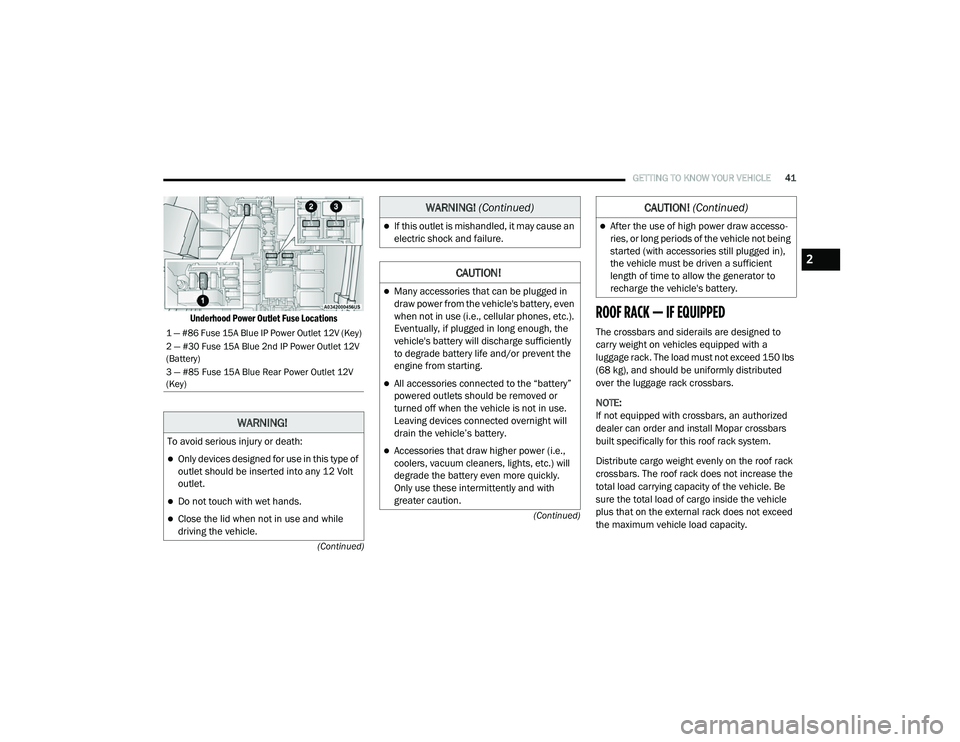
Underhood Power Outlet Fuse Locations
ROOF RACK — IF EQUIPPED
The crossbars and siderails are designed to
carry weight on vehicles equipped with a
luggage rack. The load must not exceed 150 lbs
(68 kg), and should be uniformly distributed
over the luggage rack crossbars.
NOTE:
If not equipped with crossbars, an authorized
dealer can order and install Mopar crossbars
built specifically for this roof rack system.
Distribute cargo weight evenly on the roof rack
crossbars. The roof rack does not increase the
total load carrying capacity of the vehicle. Be
sure the total load of cargo inside the vehicle
plus that on the external rack does not exceed
the maximum vehicle load capacity.1 — #86 Fuse 15A Blue IP Power Outlet 12V (Key)
2 — #30 Fuse 15A Blue 2nd IP Power Outlet 12V
(Battery)
3 — #85 Fuse 15A Blue Rear Power Outlet 12V
(Key)
WARNING!
To avoid serious injury or death:
Only devices designed for use in this type of
outlet should be inserted into any 12 Volt
outlet.
Do not touch with wet hands.
Close the lid when not in use and while
driving the vehicle.
If this outlet is mishandled, it may cause an
electric shock and failure.
CAUTION!
Many accessories that can be plugged in
draw power from the vehicle's battery, even
when not in use (i.e., cellular phones, etc.).
Eventually, if plugged in long enough, the
vehicle's battery will discharge sufficiently
to degrade battery life and/or prevent the
engine from starting.
All accessories connected to the “battery”
powered outlets should be removed or
turned off when the vehicle is not in use.
Leaving devices connected overnight will
drain the vehicle’s battery.
Accessories that draw higher power (i.e.,
coolers, vacuum cleaners, lights, etc.) will
degrade the battery even more quickly.
Only use these intermittently and with
greater caution.
WARNING! (Continued)
After the use of high power draw accesso -
ries, or long periods of the vehicle not being
started (with accessories still plugged in),
the vehicle must be driven a sufficient
length of time to allow the generator to
recharge the vehicle's battery.
CAUTION! (Continued)
2
21_VM_OM_EN_USC_t.book Page 41
Page 56 of 280

54GETTING TO KNOW YOUR INSTRUMENT PANEL
Vehicle Security Warning Light
This warning light will illuminate when
the vehicle security system has
detected an attempt to break into the
vehicle.
Engine Check/Malfunction Indicator Warning
Light (MIL)
The Engine Check/Malfunction
Indicator Light (MIL) is a part of an
Onboard Diagnostic System called
OBD II that monitors engine and
automatic transmission control systems. This
warning light will illuminate when the ignition is in
the ON/RUN position before engine start. After
placing the ignition to the ON/RUN position, if
there is a problem with the Sentry Key System,
the Vehicle Security Light will turn on. This
condition will result in the engine being shut off
after two seconds. If the bulb does not come on
when turning the ignition switch from OFF to ON/
RUN, have the condition checked promptly.
NOTE:
This warning light will illuminate when the
vehicle security system has detected an
attempt to break into the vehicle.
Certain conditions, such as a loose or missing
gas cap, poor quality fuel, etc., may illuminate the
light after engine start. The vehicle should be
serviced if the light stays on through several
typical driving styles. In most situations, the
vehicle will drive normally and will not require
towing. When the engine is running, the MIL may flash
to alert serious conditions that could lead to
immediate loss of power or severe catalytic
converter damage. The vehicle should be
serviced by an authorized dealer as soon as
possible if this occurs.
CAUTION!
The TPMS has been optimized for the original
equipment tires and wheels. TPMS pressures
and warning have been established for the
tire size equipped on your vehicle.
Undesirable system operation or sensor
damage may result when using replacement
equipment that is not of the same size, type,
and/or style. Aftermarket wheels can cause
sensor damage. Using aftermarket tire
sealants may cause the Tire Pressure
Monitoring System (TPMS) sensor to become
inoperable. After using an aftermarket tire
sealant it is recommended that you take your
vehicle to an authorized dealer to have your
sensor function checked.
WARNING!
A malfunctioning catalytic converter, as refer
-
enced above, can reach higher temperatures
than in normal operating conditions. This can
cause a fire if you drive slowly or park over
flammable substances such as dry plants,
wood, cardboard, etc. This could result in
death or serious injury to the driver, occu -
pants or others.
CAUTION!
Prolonged driving with the Malfunction
Indicator Light (MIL) on could cause damage
to the vehicle control system. It also could
affect fuel economy and driveability. If the
MIL is flashing, severe catalytic converter
damage and power loss will soon occur.
Immediate service is required.
21_VM_OM_EN_USC_t.book Page 54
Page 60 of 280

58
STARTING AND OPERATING
STARTING THE ENGINE
Before starting your vehicle, adjust your seat,
adjust both inside and outside mirrors, and
fasten your seat belts.
Automatic Transmission
The gear selector must be in the PARK (P) or
NEUTRAL (N) position before you can start the
engine. Press the brake pedal before shifting to
any driving gear.
NOTE:
You must press the brake pedal before shifting
out of PARK.
Normal Starting
Turn the ignition switch to the AVV (START)
position and release it when the engine starts.
If the engine fails to start within 10 seconds,
turn the ignition switch to the STOP (OFF/LOCK)
position, wait 10 to 15 seconds, then repeat
this procedure.
Cold Weather Operation
To ensure reliable starting at low temperatures,
use of an externally powered electric engine
block heater (available from an authorized
dealer) is recommended.To prevent possible engine damage while
starting at low temperatures, this vehicle will
inhibit engine cranking when the ambient
temperature is less than -31°F (-35° C) and the
oil temperature sensor reading indicates an
engine block heater has not been used. The
message “plug in engine heater” will be
displayed in the instrument cluster when the
ambient temperature is below -25°F (-32° C) at
the time the engine is shut off as a reminder.
Extended Park Starting
NOTE:
Extended Park condition occurs when the
vehicle has not been started or driven for at
least 30 days.
1. Install a battery charger or jumper cables
to the battery to ensure a full battery
charge during the crank cycle.
2. Place the ignition in the AVV (START) position and release it when the engine
starts.
WARNING!
Never leave children alone in a vehicle, or
with access to an unlocked vehicle.
Allowing children to be in a vehicle unat -
tended is dangerous for a number of
reasons. A child or others could be seriously
or fatally injured. Children should be
warned not to touch the parking brake,
brake pedal or the transmission gear
selector.
Do not leave the key fob in or near the
vehicle (or in a location accessible to chil -
dren). A child could operate power
windows, other controls, or move the
vehicle.
21_VM_OM_EN_USC_t.book Page 58
Page 61 of 280
STARTING AND OPERATING59
3. If the engine fails to start within ten
seconds, place the ignition in the STOP
(OFF/LOCK) position, wait five seconds to
allow the starter to cool, then repeat the
Extended Park Starting procedure.
4. If the engine fails to start after eight attempts, allow the starter to cool for at
least 10 minutes, then repeat the
procedure.
If Engine Fails To Start
If the engine fails to start after you have
followed the “Normal Starting” or “Extreme Cold
Weather” procedure, and has not experienced
an extended park condition as identified in
“Extended Park Starting” procedure, it may be
flooded. Push the accelerator pedal all the way
to the floor and hold it there. Crank the engine
for no more than 15 seconds. This should clear
any excess fuel in case the engine is flooded. Leave the ignition key in the MAR (ON/RUN)
position, release the accelerator pedal and
repeat the “Normal Starting” procedure.
After Starting
The idle speed is controlled automatically, and
it will decrease as the engine warms up.
ENGINE BLOCK HEATER — IF EQUIPPED
The engine block heater warms the engine and
permits quicker starts in cold weather.
Connect the cord to a 110-115 Volt AC electrical
outlet with a grounded, three-wire extension
cord.
For ambient temperatures below 0°F (-18°C),
the engine block heater is recommended. For
ambient temperatures below -20°F (-29°C),
the engine block heater is required.
The engine block heater cord is routed under
the hood, behind to the driver’s side headlamp.
Follow the steps below to properly use the
engine block heater:
CAUTION!
To prevent damage to the starter, do not
crank continuously for more than 10 seconds
at a time. Wait 10 to 15 seconds before trying
again.
WARNING!
Never pour fuel or other flammable liquid
into the throttle body air inlet opening in an
attempt to start the vehicle. This could
result in flash fire causing serious personal
injury.
Do not attempt to push or tow your vehicle
to get it started. Vehicles equipped with an
automatic transmission cannot be started
this way. Unburned fuel could enter the
catalytic converter and once the engine has
started, ignite and damage the converter
and vehicle.
If the vehicle has a discharged battery,
booster cables may be used to obtain a
start from a booster battery or the battery in
another vehicle. This type of start can be
dangerous if done improperly
Úpage 204.
CAUTION!
To prevent damage to the starter, do not
continuously crank the engine for more than
25 seconds at a time. Wait 60 seconds
before trying again.
4
21_VM_OM_EN_USC_t.book Page 59
Page 63 of 280
STARTING AND OPERATING61
(Continued)
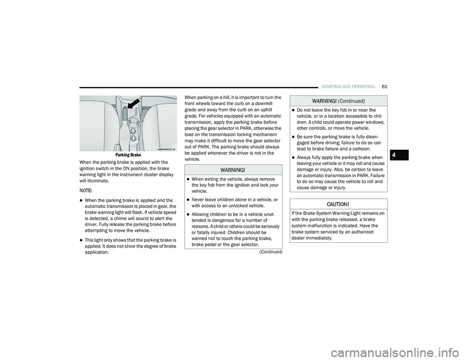
Parking Brake
When the parking brake is applied with the
ignition switch in the ON position, the brake
warning light in the instrument cluster display
will illuminate.
NOTE:
When the parking brake is applied and the
automatic transmission is placed in gear, the
brake warning light will flash. If vehicle speed
is detected, a chime will sound to alert the
driver. Fully release the parking brake before
attempting to move the vehicle.
This light only shows that the parking brake is
applied. It does not show the degree of brake
application. When parking on a hill, it is important to turn the
front wheels toward the curb on a downhill
grade and away from the curb on an uphill
grade. For vehicles equipped with an automatic
transmission, apply the parking brake before
placing the gear selector in PARK, otherwise the
load on the transmission locking mechanism
may make it difficult to move the gear selector
out of PARK. The parking brake should always
be applied whenever the driver is not in the
vehicle.
WARNING!
When exiting the vehicle, always remove
the key fob from the ignition and lock your
vehicle.
Never leave children alone in a vehicle, or
with access to an unlocked vehicle.
Allowing children to be in a vehicle unat
-
tended is dangerous for a number of
reasons. A child or others could be seriously
or fatally injured. Children should be
warned not to touch the parking brake,
brake pedal or the gear selector.
Do not leave the key fob in or near the
vehicle, or in a location accessible to chil -
dren. A child could operate power windows,
other controls, or move the vehicle.
Be sure the parking brake is fully disen -
gaged before driving; failure to do so can
lead to brake failure and a collision.
Always fully apply the parking brake when
leaving your vehicle or it may roll and cause
damage or injury. Also, be certain to leave
an automatic transmission in PARK. Failure
to do so may cause the vehicle to roll and
cause damage or injury.
CAUTION!
If the Brake System Warning Light remains on
with the parking brake released, a brake
system malfunction is indicated. Have the
brake system serviced by an authorized
dealer immediately.
WARNING! (Continued)
4
21_VM_OM_EN_USC_t.book Page 61