2021 MERCEDES-BENZ GLE COUPE tow
[x] Cancel search: towPage 366 of 525
Mercedes-Benz
recommends transporting your
ve hicle in the case of a breakdown, rath er than
to wing it away.
Fo rto wing, use a tow rope or tow bar with bo th
axles on the ground. Do not use tow bar sys‐
te ms. *
NO
TEDama getotheve hicle due to tow‐
ing away incor rectly #
Obser vethe instructions and no tes on
to wing away. Pe
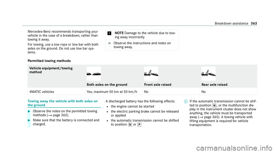
rm itted towing me thods Ve
hicle equipment/ towing
me thod Bo
th axles on thegr ound Fr
ont axle raised Re
ar axle raised
4MATIC vehicles Yes, maximum 50 km at 50 km/h No NoTo
wing away theve hicle with bo thaxles on
th egr ound #
Obser vethe no tes on the permitted towing
me thods (/ page 362). #
Make sure that the battery is connected and
ch arge d. A dischar
ged battery has thefo llowing ef fects:
R the engine cann otbe star ted
R the electric parking brake cann otbe released
or applied
R the automatic transmission cann otbe shif ted
to position 005Cor005D %
Ifth e automatic transmission cann otbe shif‐
te dto position 005C, orthe multifunction dis‐
play in the instrument clus ter does not show
anything, theve hicle must be transpor ted
aw ay ( /page 365). A towing vehicle with
lifting equipment is requ ired forve hicle
transpor tation. Breakdown assi
stance 363
Page 367 of 525
*
NO
TEDama gedue to to wing away at
exc essively high speeds or over long dis‐
ta nces The driv
etra in could be damaged when tow‐
ing at excessively high speeds or over long
dis tances. #
Atowing speed of 50 km/h must not
be exc eeded. #
Atowing dis tance of 50 km must not be
exc eeded. &
WARNING Risk of accident when towing
a ve hicle which is too heavy
If th eve hicle being tow- star ted or towed
aw ay is heavier than the permissible gross
mass, thefo llowing situations can occur:
R theto wing eye may become de tach ed.
R the car/t railer combination may swer ve
or eve nove rturn. #
If ano ther vehicle is tow- star ted or
to we daw ay, its weight must not exceed th
e permissible gross mass of your own
ve hicle. #
Information on the permissible gross mass of
th eve hicle can be found on theve hicle iden‐
tification plate (/ page 391). #
Do not open the driver's door or front
passenger door as the automatic transmis‐
sion may otherwise shift toposition 005Dauto‐
maticall y. #
Fittheto wing eye (/ page 366). #
Fasten theto w bar.
* NO
TEDama gedue toincor rect connec‐
tion of theto w bar #
Onlyconnect theto w rope or tow bar to
th eto wing eyes. %
You can also attach theto w bar tothe trailer
hitch. #
Deactivate the automatic locking mechanism
(/ page 81). #
Do not activate the HOLD function. #
Deactivate tow- aw ay protection
(/ page 97). #
Deactivate Active Brake Assi st
( / page 227). #
Shift the automatic transmission toposition
005C(/ page182). #
Release the electric parking brake. &
WARNING Risk of accident due tolimi‐
te d saf ety-re lated functions during the
to wing process
Saf ety-re lated functions are limited or no lon‐
ge rav ailable in thefo llowing situations:
R the ignition is switched off.
R the brake sy stem or po werst eering sys‐
te m is malfunctioning.
R the energy supply or the on-board electri‐
cal sy stem is malfunctioning.
When your vehicle is then towe daw ay, signif‐
icantly more ef fort may be requ ired tosteer
and brake than is norm allyrequ ired. #
Use a tow bar. 364
Breakdown assis tance
Page 368 of 525
#
Make sure that thesteering wheel can
mo vefreely, before towing theve hicle
aw ay. *
NO
TEDama gedue toexcessive tracti ve
po wer If
yo u pull away sharpl y,the tractive po wer
may be too high and theve hicles could be
damaged. #
Pull away slowly and smoo thly. Loading the
vehicle for transport #
Obser vethe no tes on towing away
( / page 363). #
Connect theto w bar totheto wing eye in
order toload theve hicle.
% You can also attach theto w bar tothe trailer
hitch. #
Shift the automatic transmission toposition
005C. %
The automatic transmission may be loc ked
in position 005Dintheeve nt of damage tothe
electrics. Toshift to005C , pr ovide the on-
board electrical sy stem with po wer
( / page 361). #
Load theve hicle onto the transpor ter. #
Shift the automatic transmission toposition
005D. #
Use the electric parking brake tosecure the
ve hicle against rolling away. #
Only secure theve hicle bythe wheels.
Ve hicles with ADS PLUS (Adaptive Damping
Sy stem PLUS) &
WARNING Risk of an accident when
transporting vehicles with Adaptive
Damping Sy stem PLUS
The reduced damping forc es on theve hicle
being transpor ted can cause theve hicle/
trailer combination tostart toswing.
As a result, when transporting vehicles with
th eAd aptive Damping Sy stem PLUS, the ve
hicle/trailer combination may start toskid.
Consequentl y,yo u could lose cont rol of your
ve hicle. #
When transporting, ensure that:
R theve hicle has been loaded onto
th e transpor ter cor rectly
R theve hicle is secured at all four
wheels with suitable tensioning
st ra ps
R the maximum permissible speed of
60 km/h is not exceeded when
transporting *
NO
TEDama getotheve hicle from secur‐
ing it incor rectly #
After loading, theve hicle must be
secured on all four wheels. Otherwise,
th eve hicle could be damaged. #
A minimum dis tance of 20 cm up wards
and 10cm down wards must be kept to
th e transport platform. Breakdown assis
tance 365
Page 370 of 525
to
wing eye. Fasten theto w bar tothe trailer
hitch. #
Make sure that co ver1 engages in the
bumper when youre mo vetheto wing eye.
* NO
TEDama getotheve hicle due to
incor rect use of theto wing eye or trailer
hitch When a
towing eye or trailer hitch is used to
re co ver a vehicle, theve hicle may be dam‐
aged in the process. #
Only use theto wing eye or trailer hitch
to to waw ay ortow start theve hicle. #
Do not use theto wing eye or trailer
hitch to towtheve hicle during reco very. To
w starting theve hicle (eme rgency engine
st art) Ve
hicles with automatic transmission
* NO
TEDama getothe automatic trans‐
mission due to tow-starting The automatic transmission may be damaged
in
the process of tow- starting vehicles with
automatic transmission. #
Vehicles with automatic transmission
must not be tow- star ted. #
Vehicles with automatic transmission must
not be tow- star ted. Electrical fuses
Note
s on electrical fuses &
WARNING Risk of accident and inju ry
due to ov erloaded lines
If yo u manipulate or bridge a faulty fuse or if
yo ure place it with a fuse with a higher amperage,
the electric line could be overloa‐
ded.
This could result in a fire. #
Alw aysre place faulty fuses with speci‐
fi ed new fuses conta iningthe cor rect
amperage. *
NO
TEDama gedue toincor rect fuses Electrical components or sy
stems may be
damaged byincor rect fuses, or their func‐
tionality may be significant lyimpaired. #
Only use fuses that ha vebeen appr oved
by Mercedes-Benz and which ha vethe
cor rect fuse rating. Blown fuses mu
stbe replaced with fuses of the
same rating, which you can recognise bythe col‐
our and the label. The fuse ratings and fu rther
information tobe obser ved can be found in the
fuse assignment diagram.
Fu se assignment diag ram: onthe fuse box in
th e load compartment (/ page 369). Breakdown assis
tance 367
Page 388 of 525
#
Remo vethest icke r with the label 80 km/h
from the tyre inflation compressor housing
and af fix it tothe instrument clus ter within
th e driver's field of vision. #
Remo vethe tyre inflation compressor from
th estow age space under the luggage com‐
partment floor (/ page 352). #
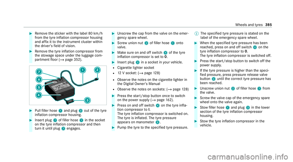
Pull filler hose 1and plug 3out of the tyre
inflation compressor housing. #
Insert plug 7offiller hose 1inthe soc ket
on the tyre inflation compressor and then
turn it until plug 7engages. #
Unscr ew the cap from theva lve on the emer‐
ge ncy spa rewheel. #
Screw union nut 2offiller hose 1onto
va lve. #
Make sure on and off switch 4ofthe tyre
inflation compressor is set to0. #
Insert plug 3in a soc ket in your vehicle.
R Cigar ette lighter soc ket
R 12V soc ket: ( / page 128)
R Obse rveth e no tes on the cigar ette lighter in
th e Digital Owner's Manual
R Obser vethe no tes on soc kets: (/ page 128) #
Press thest art/ stop button once toswitch
on the po wer supp ly (/ page162). #
Press on and off swit ch4 onthe tyre infla‐
tion compressor toI.
The tyre inflation compressor is switched on.
The tyre is inflated. The tyre pressure
appears on manome ter5. #
Pump the tyre tothe specified tyre pressure. %
The specified tyre pressure is stated on the
label of the emer gency spa rewheel. #
When the specified tyre pressure has been
re ached, press on and off swit ch4 onthe
tyre inflation compressor to0.
The tyre inflation compressor is switched off. #
Press thest art/ stop button toswitch off the
po we r supp ly. #
Ifth e tyre pressure is higher than the speci‐
fi ed pressure, press pressure release valve
button 6until the cor rect tyre pressure has
been reached. #
Unscr ew union nut 2offiller hose 1from
th eva lve. #
Screw theva lve cap of the emer gency spa re
wheel onto theva lve again. #
Stow filler hose 1and plug 3inthe lo wer
section of the tyre inflation compressor
housing. #
Stow th e tyre inflation compressor in the
ve hicle. Wheels and tyres
385
Page 390 of 525
#
Alw aysst ore the collapsible spare
wheel in the emer gency spa rewheel
bag and attach it tothe brac ket in the
load compartment. #
Alw ays ensure that the lashing stra ps
on the emer gency spa rewheel bag are
safely secured on there ar tie-down
ey es on the load compartment floor. Depending on
theve hicle's equipment, the col‐
lapsible spare wheel is located in an emer gency
spa rewheel bag on a brac ket in the load com‐
partment. The collapsible spare wheel in the
emer gency spa rewheel bag and the brac ket are
lashed wi thstra ps and secured using there ar
tie-down eyes on the load compartment floor. Re
moving the collapsible spare wheel Ve
hicles without a Burmes ter sound sy stem
The collapsible spare wheel is located under the
load compartment floor. #
Obser vethe information on mounting tyres
(/ page 374). #
Open theta ilgate. #
Open the load compartment floor. #
Remo vethe collapsible spare wheel.
Ve hicles with a Burmes ter sound sy stem
The collapsible spare wheel is secured in the col‐
lapsible spare wheel bag in the load compart‐
ment. #
Obser vethe information on mounting tyres
(/ page 374). #
Open the load compartment. #
Loosen the lashing stra ps. #
Unhook there taining spring hooks of the
lashing stra ps from the brac kets. #
Remo vethe collapsible spare wheel bag
to ge ther with the collapsible spare wheel. #
Open the collapsible spare wheel bag and
re mo vethe collapsible spare wheel. Inflating
the collapsible spa rewheel Re
quirements:
R Mount the collapsible spare wheel as descri‐
bed (/ page 382).
R Remo vethe tyre inflation compressor from
th estow agewell under the boot floor
(/ page 352).
* NO
TEDama getothe collapsible spare
wheel when lo wering theve hicle Lo
we ring theve hicle without pr eviously
inflating the collapsible spare wheel can
damage its rim. #
Inflate the collapsible spare wheel using
th e tyre inflation compressor before
lo we ring theve hicle. *
NO
TEOverheating due tothe tyre infla‐
tion compressor running too long #
Do not runth e tyre inflation compres‐
sor for longer than ten minu tes without
inter ruption. Wheels and tyres
387
Page 392 of 525
Note
s ontech nical data
* NO
TEMercedes-AMG vehicles #
Obser vethe no tes in the Supplement.
Yo u could otherwise failto recognise
dangers. *
NO
TEPlug-in hybrid #
Obser vethe no tes in the Supplement.
Yo u could otherwise failto recognise
dangers. The
tech nical da tawa s de term ined in accord‐
ance with EU Directives. The data stated only
applies tovehicles with standard equipment. Yo u
can obtain fur ther information from a Mercedes-
Benz Service Centre.
Only for ce rtain countries: you can find vehi‐
cle-specific vehicle data in the COC documents
(CERTIFIC ATE OF CONFORMITY). These pape rs
are included with theve hicle. On-board electronics
Note
s on tampering with the engine elec‐
tronics *
NO
TEPremature wearthro ugh improper
main tenance Improper maintenance may cause
vehicle
components towe ar more quickly and the
ve hicle's operating permit may be in valida‐
te d. #
Alw ays ha vewo rkon the engine elec‐
tronics and related components car ried
out at a qualified specialist workshop. Tw
o-w ayradios Note
s onfitting two-w ayradios &
WARNING Risk of accident due to
improper workon two-w ayradios
If two-w ayradios are manipulated or retrofit‐
te d incor rectl y,the electromagnetic radiation
from the two-w ayradios can inter fere with th
eve hicle electronics and jeopardise the
operating saf ety of theve hicle. #
You should ha veall workon electrical
and electronic components car ried out
at a qualified specialist workshop. &
WARNING Risk of accident from incor‐
re ct ope ration of two-w ayradios
If yo u use two- wayra dios in theve hicle
improperly, their electromagnetic radiation
can disrupt theve hicle's electronics. This is
true in thefo llowing situations, in particular:
R The two-w ayradio is not connec tedto an
ex terior aerial.
R The exterior aerial is fitted inco rrectly or
is not a lo w-reflection aerial.
This could jeopardise the operating saf ety of
th eve hicle. #
Have the lo w-reflection exterior aerial
fi tted at a qualified specialist workshop. Te
ch nical da ta389
Page 408 of 525
All models (vehi‐
cles with AMG
Styl
ing) 1 1
Front 2 2Rear
Ve hicles with
st eel suspen‐
sion* 21
°2 2°
Ve hicles with
AIRMATIC*
Normal le vel2 1°21 °
Ra ised le vel2 4°24 ° *Depending on
the tyre size
Maximum gradient climbing ability
The vehicle's gradient climbing ability depends
on thewe ight distribution in theve hicle, thete r‐
ra in conditions and thero ad sur face conditions.
The specified value applies in thefo llowing
cases:
R theve hicle is ready todrive – fuel tank full,
all fluids topped up, driver in theve hicle R
thero ad sur face conditions and thus traction
are good
A gradient climbing ability of 100% cor responds
to an incline of 45°.
Obse rveth e no tes on driving in mountainous ter‐
ra in (/ page170). Mo
del Maximumgra‐
dient climbing ability
All models 80 % Tr
ailer hitch Gene
ral no tes on the trailer hit ch Modifications
tothe engine cooling sy stem may
be necessar y,depending on theve hicle model.
The retrofitting of a trailer hitch is only pe rmissi‐
ble if a towing capacity is specified in your vehi‐
cle documents.
Fu rther information can be obtained at a quali‐
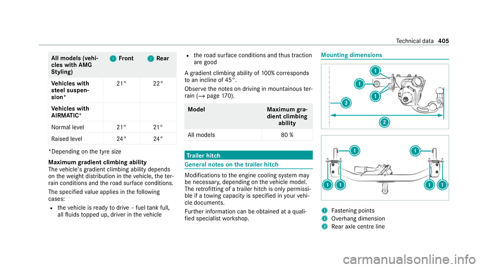
fi ed specialist workshop. Mounting dimensions
1
Fastening points
2 Overhang dimension
3 Rear axle centre line Te
ch nical da ta405