2021 MERCEDES-BENZ GLE COUPE charging
[x] Cancel search: chargingPage 5 of 525
Symbols
........................................................ 5At
agl ance .................................................... 6
Cockpit ........................................................... 6
Indica tor and warning lamps ........................ .10
Overhead contro l panel ................................ 12
Door operating unit and seat adjustment ..... 14
Control settings in there ar passenger
compartment ................................................ 16
Emergencies and breakdowns ...................... 18Digital Owner's Manual
.............................20
Calling up the Digital Owner's Manual ..........20 Genera
l notes............................................. 22
Pr otection of the environment ......................22
Ta ke -ba ckof end-of-life vehicles ...................22
Mercedes-Benz GenuineParts ....................... 23
Owner's Manual ............................................ 24
Operating saf ety .......................................... .24
Declaration of conformity ............................. 26
Diagno stics connection ................................ 31
Qualified specialist workshop ....................... 33 Ve
hicle registration ....................................... 33
Cor rect use of theve hicle ............................33
Information on the REA CHregulation ........... 34
No tesfo r persons with electronic medi‐
cal aids ......................................................... 34
Implied warranty .......................................... .35
QR code forre scue card ...............................35
Data storage .................................................35
Copyright ...................................................... 38 Occupant saf
ety......................................... 39
Re stra int sy stem ...........................................39
Seat belts ...................................................... 41
Airbags ......................................................... 45
PRE-SAFE ®
sy stem ....................................... 52
Au tomatic measure s after an accident ......... 54
Safely transporting children in theve hi‐
cle ................................................................54
No tes on pets in theve hicle .........................73 Opening and closing
.................................. 75
Ke y .............................................................. .75
Doo rs............................................................ 78
Load compartment ....................................... 83 Side windo
ws............................................... 88
Sliding sunroof .............................................. 91
Anti-theft pr otection .....................................95 Seats and
stowing ..................................... 99
No tes on the cor rect driver's seat posi‐
tion ............................................................... 99
Seats ............................................................ 99
St eering wheel ............................................ 11 0
Easy entry and exitfeature .......................... 111
Memory function ......................................... 11 3
St ow age areas ............................................ .114
Cup holders ................................................ 127
Soc kets ....................................................... 12 8
Wi reless charging of the mobile phone
and connection with theex terior aerial ...... 13 0
Fitting/removing thefloor mats ................. 13 2 Light and sight
......................................... 13 3
Exterior lighting .......................................... 13 3
Interior lighting ........................................... 14 0
Wi ndsc reen wipers and windscreen
wa sher sy stem ............................................ 14 2
Mir rors ........................................................ 14 52
Contents
Page 35 of 525
th
e scope of repair and maintenance workor for
re ading out vehicle data bya specialist work‐
shop. Diagnostic devices should therefore only
be connected byaqu alified specialist workshop. &
WARNING Risk of accident due tocon‐
necting devices tothe diagnostics con‐
nection
If yo u connect devices tothe diagnostics
connection of theve hicle, the function of
ve hicle sy stems and operating saf ety may be
impaired. #
For saf etyre asons, werecommend that
yo u on lyuse and connect products
appr ovedby yo ur Mercedes-Benz
service centre. &
WARNING Risk of accident due to
objects in the driver's foot we ll
Objects in the driver's foot we ll may impede
pedal tr avel or block a depressed pedal.
This jeopardises the operating and road
saf ety of theve hicle. #
Stow all objects in theve hicle securely
so that they cannot getinto the driver's
fo ot we ll. #
Alw aysfit th efloor mats securely and
as prescribed in order toensure that
th ere is alw ays suf ficient room forthe
pedals. #
Do not use loose floor mats and do not
place floor mats on top of one ano ther. *
NO
TEBattery discharging from using
devices connected tothe diagnostics
connection Using devices at
the diagnostics connection
drains the batter y. #
Check thech arge leve l of the batter y. #
Ifth ech arge leve l is lo w,charge the
batter y,e.g. bydriving a considerable
dis tance. Please also no
tethe information about the12 V
battery and short-dis tance trips in the "Driving
and Parking" chap ter (/ page167). Con
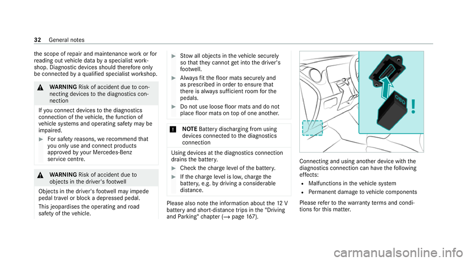
necting and using ano ther device with the
diagnostics connection can ha vethefo llowing
ef fects:
R Malfunctions in theve hicle sy stem
R Perm anent damage tovehicle components
Please referto thewa rranty term s and condi‐
tions forth is matter. 32
General no tes
Page 133 of 525
Wire
lesscharging of the mobile phone and
connection with theex terior aerial Note
s on wirelessly charging the mobile
phone &
WARNING Risk of injury duetoobjects
being stowed incor rectly
If objects in theve hicle interior are stowed
incor rectly, they can slide or be thrown
around and hit vehicle occupants. In addi‐
tion, cup holders, open stowage spaces and
mobile phone recep tacles cannot al ways
re tain all objects within.
There is a risk of injur y,particularly in the
ev ent of sudden braking or a sudden change
in direction. #
Alw aysstow objects so that they can‐
not be throw n around in su chsitua‐
tions. #
Alw ays make sure that objects do not
pr otru de from stowage spaces, luggage
nets or stowage nets. #
Close the loc kable stow age spaces
before starting a journe y. #
Alw aysstow and secure heavy, hard,
poin ted, sharp-edged, fragile or bulky
objects in the boot/load compartment. Obser
vethe no tes on loading theve hicle. &
WARNING Risk offire from placing
objects in the mobile phone stowage
compartment
Placing other objects in the mobile phone
stow age compartment could con stitute a fire
hazard. #
Apart from a mobile phone, do not
place any other objects in the mobile
phone stowage compartment, espe‐
cially those made of me tal. *
NO
TEDama getoobjects caused by
placing them in the mobile phone stow‐
age compartment If objects are placed in
the mobile phone
stow age compartment, they may be dam‐
aged byelectromagnetic fields. #
Do not place credit cards, data storage
devices, ski passes or other objects
sensitive toelectromagnetic fields in
th e mobile phone stowage compart‐
ment. *
NO
TEDama getothe mobile phone
stow age compartment caused byliquids If liquids enter
the mobile phone stowage
compartment, the compartment may be
damaged. #
Ensure that no liquids enter the mobile
phone stowage compartment. Alw
ays obser vethe no tesfo r persons with elec‐
tronic medical aids (/ page 34).13 0
Seats and stowing
Page 134 of 525
R
Depending on theve hicle equipment, the
mobile phone is connected totheve hicle's
ex terior aerial via thech arging module.
R The charging function and wireless connec‐
tion of the mobile phone totheve hicle's
ex terior aerial are only available if the ignition
is switched on.
R Small mobile phones may not be able tobe
ch arge d in everyposition of the mobile
phone stowage compartment.
R Largemobile phones which do not rest flat in
th e mobile phone stowage compartment may
not be able tobe charge d or connec ted with
th eve hicle's exterior aerial.
R The mobile phone may heat up during the
ch arging process. This may also depend on
th e applications (apps) cur rently open in the
bac kground.
R Toensure more ef ficient charging and con‐
nection with theve hicle's exterior aerial,
re mo vethe pr otective co ver from the mobile
phone. Pr otective co vers which are neces‐
sary for wireless charging are an exception. Wire
lesscharging of a mobile phone in the
cockpit Re
quirements:
R The mobile phone is suitable for wireless
ch arging.
% A list of compatible mobile phones can be
found at: https://www.mercedes-benz-
mobile.com/ #
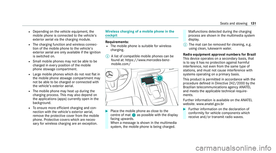
Place the mobile phone as close tothe
centre of mat 1as possible with th e display
fa cing up wards.
When a message is shown in the multimedia
sy stem, the mobile phone is being charge d. Malfunctions de
tected duri ngthech arging
process are shown in the multimedia sy stem
displa y.
% The mat can be remo vedfo r cleaning, e.g.
using clean, luk ewarmwate r.
Ra dio equipment appr oval numbers for Brazil
This device operates on a secondary basis, that
is to say it has no pr otection against harmful
inter fere nce, not even from the same type of
st ations, and must not cause inter fere nce wi th
sy stems operating on a primary basis.
This product is permitted in accordance with the
procedure defined in Directive 242/2000 bythe
Brazilian telecommunications agency AN ATEL
and meets the applicable tech nical requ ire‐
ments.
Fu rther information is available on the AN ATEL
we bsite. www.anatel.go v.br #
Further information on the declaration of
confo rmity forve hicle components which
re cei veand/or transmit radio wav es. Seats and
stowing 131
Page 137 of 525
004B
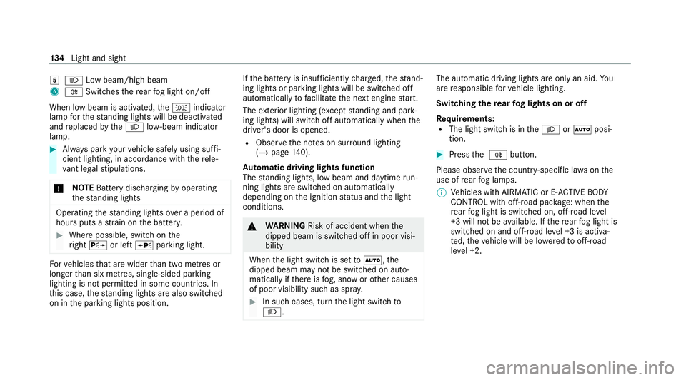
0058 Low beam/high beam
6 005E Switches there ar fog light on/off
When low beam is activated, the0060 indicator
lamp forth est anding lights will be deactivated
and replaced bythe0058 low- beam indicator
lamp. #
Alw ays park your vehicle safely using suf fi‐
cient lighting, in acco rdance with there le‐
va nt le galst ipulations.
* NO
TEBattery discharging byoperating
th est anding lights Operating
thest anding lights over a period of
hours puts a stra in on the batter y. #
Where possible, switch on the
ri ght 0064 or left 0063parking light. Fo
rve hicles that are wider than two metres or
lon gerth an six metres, sin gle-sided parking
lighting is not permitted in some count ries. In
th is case, thest anding lights are also swit ched
on in the parking lights position. If
th e battery is insuf ficiently charge d, thest and‐
ing lights or parking lights will be swit ched off
automatically tofacilitate the next engine start.
The exterior lighting (e xcept standing and park‐
ing lights) will swit choff automatically when the
driver's door is opened.
R Obser vethe no tes on sur round lighting
(/ page 140).
Au tomatic driving lights function
The standing lights, low beam and daytime run‐
ning lights are switched on au tomatically
depending on the ignition status and the light
conditions. &
WARNING Risk of accident when the
dipped beam is switched off in poor visi‐
bility
When the light switch is set to0058 ,the
dipped beam may not be switched on auto‐
matically if there is fog, snow or other causes
of poor visibility such as spr ay. #
In such cases, turn the light switch to
0058 . The automatic driving lights are only an aid.
Yo u
are responsible forve hicle lighting.
Switching there ar fog lights on or off
Re quirements:
R The light switch is in the0058 or0058 posi‐
tion. #
Press the 005E button.
Please obser vethe count ry-specific la wsonthe
use of rear fog lamps.
% Vehicles with AIRMATIC or E- ACTIVE BODY
CO NTROL with off-road pac kage : when the
re ar fog light is switched on, off-road le vel
+3 will not be available. If there ar fog light is
switched on and off-road le vel +3 is activa‐
te d, theve hicle will be lo weredto off-road
le ve l +2. 134
Light and sight
Page 167 of 525
St
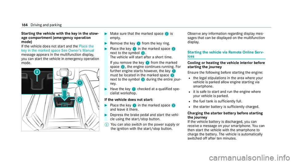
arting theve hicle with theke y in thesto w‐
age compa rtment (emer gency operation
mode)
If th eve hicle does not start and thePlace the
key in the marked space See Owner's Manual
message appears in the multifunction displa y,
yo u can start theve hicle in emer gency operation
mode. #
Makesure that the mar ked space 2is
em pty. #
Remo vetheke y1 from theke yring. #
Place theke y1 inthe mar ked space 2
next tothe symbol 3.
The vehicle will start af ter a short time.
If yo ure mo vetheke y1 from the mar ked
space 2,the engine continues running. For
fur ther engine starts ho wever,th eke y1
must be located in the mar ked space 2
next tothe symbol 3during the entire jour‐
ne y. #
Have theke y1 checked at a qualified spe‐
cialist workshop.
If th eve hicle does not star t: #
Place theke y1 inthe mar ked space 2
and lea veitth ere. #
Depress the brake pedal and start theve hi‐
cle using thest art/ stop button.
% You can also swit chon the po wer supp lyor
th e ignition with thest art/ stop button. Obser
veany information rega rding display mes‐
sages that can be displa yed on the multifunction
displa y. St
arting theve hicle via Remo teOnline Serv‐
ices Cooling or heating
theve hicle interior before
st arting the jou rney
Ensu rethefo llowing before starting the engine:
R the legal stipulations in the area where your
ve hicle is par ked allow engine starting via
smartphone.
R it is safe tostart and runth e engine where
yo ur vehicle is par ked.
R the fuel tank is su fficiently full.
R thest ar ter battery is suf ficiently charge d.
Charging thest ar ter battery be fore starting
th e jou rney
If th eve hicle battery is dischar ged, you can
re cei vea message on your smartphone. You can
th en start theve hicle with the smartphone to
ch arge the batter y.The vehicle is automatically
switched off af terte n minu tes. 16 4
Driving and pa rking
Page 200 of 525
Information on collision de
tection on a
pa rked vehicle If a collision is de
tected when theto w- aw ay pro‐
te ction is primed on a loc kedve hicle, you will
re cei vea notification in the multimedia sy stem
when you swit chon the ignition.
Yo u will recei veinformation about thefo llowing
points:
R The area of theve hicle that may ha vebeen
damaged.
R The forc e of the impact.
The following situations can lead toinadver tent
acti vation:
R The pa rked vehicle is mo ved, e.g. in a two-
st or ey garage.
% Deactivate tow- aw ay protection in order to
pr eve nt inadver tent acti vation. If you deacti‐
va te tow- aw ay protection, collision de tection
will also be deactivated. Sy
stem limits
De tection may be restricted in thefo llowing sit‐
uations:
R theve hicle is damaged without impact, e.g. if
an outside mir ror is torn off or the paint is
damaged byakey
R an impact occurs at low speed
R the electric parking brake is not applied Note
s on parking up theve hicle If
yo u lea vetheve hicle par ked up for longer than
six weeks, it may suf fer dama gethro ugh disuse.
The 12V battery may also be impaired or dam‐
aged byheavy discharging.
% Further information can be obtained at a
qu alified specialist workshop.
* NO
TEPlug-in hybrid #
Obser vethe no tes about the high-volt‐
age battery in the Supplement. Yo u
could otherwise failto recognise dan‐
ge rs. St
andby mode (extension of the star ter bat‐
te ry 's period out of use) St
andby mode function
% This function is not available for all models.
If standby mode is activated, ene rgy loss will be
minimised during extended pe riods of non-oper‐
ation.
St andby mode is characterised bythefo llowing:
R The star ter battery is preser ved.
R The maximum non-operational time appears
inthe media displa y.
R The connection toonline services is inter rup‐
te d.
R The ATA (anti-theft alarm sy stem) is una vaila‐
ble.
R The interior pr otection and tow- aw ay protec‐
tion functions are not available.
R The function for de tecting collisions on a
pa rked vehicle is not available. Driving and parking
197
Page 274 of 525
R
Blind Spot Assi stor Active Blind Spot Assi st
R Drive AwayAssi st
R Cross Traf fic Alert
R Reversing camera
R 360° Camera
R AIRMATIC
R E-AC TIVE BODY CONTROL
Coupling up a trailer
* NO
TEDama getothest ar ter battery due
to full discharge Charging
the trailer battery using the po wer
supply of the trailer can damage thest ar ter
batter y. #
Do not use theve hicle's po wer supply
to charge the trailer batter y. #
Remo vethe co ver cap from the ball head and
st ore it in a safe place. #
Position the trailer on a le vel sur face behind
th eve hicle and couple it up totheve hicle. #
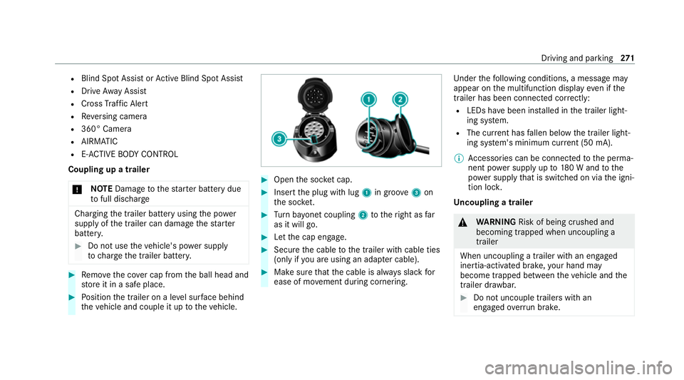
Open the soc ket cap. #
Inse rtthe plug with lug 1in groo ve3 on
th e soc ket. #
Turn bayonet coupling 2totheright as far
as it will go. #
Let the cap engage. #
Secure the cable tothe trailer with cable ties
(only if you are using an adap ter cable). #
Make sure that the cable is alw ays slack for
ease of mo vement during cornering. Under
thefo llowing conditions, a message may
appear on the multifunction display even if the
trailer has been connected cor rectly:
R LEDs ha vebeen ins talled in the trailer light‐
ing sy stem.
R The cur rent has fallen below the trailer light‐
ing sy stem's minimum cur rent (50 mA).
% Accessories can be connected tothe perma‐
nent po wer supp lyup to180 W and tothe
po we r supp lythat is swit ched on via the igni‐
tion loc k.
Un coupling a trailer &
WARNING Risk of being crushed and
becoming trapped when uncoupling a
trailer
When uncoupling a trailer with an engaged
ine rtia-activated brake, your hand may
become trapped between theve hicle and the
trailer dr awbar. #
Do not uncouple trailers with an
engaged overrun brake. Driving and pa
rking 271