2021 CHRYSLER 300 clock
[x] Cancel search: clockPage 42 of 268
40 GETTING TO KNOW YOUR VEHICLE
EXTERIOR LIGHTS
HEADLIGHT SWITCH
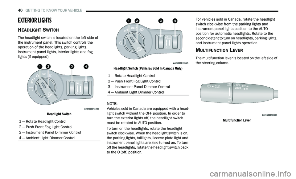
The headlight switch is located on the left side of
the instrument panel. This switch controls the
operation of the headlights, parking lights,
instrument panel lights, interior lights and fog
lights (if equipped).
Headlight Switch Headlight Switch (Vehicles Sold In Canada Only)
NOTE:
Vehicles sold in Canada are equipped with a head -
light switch without the OFF position. In order to
t u
rn the exterior lights off, the headlight switch
must be rotated to AUTO position.
To turn on the headlights, rotate the headlight
s w
itch clockwise. When the headlight switch is on,
the parking lights, taillights, license plate light and
instrument panel lights are also turned on. To turn
off the headlights, rotate the headlight switch back
to the O (off) position. For vehicles sold in Canada, rotate the headlight
sw
itch clockwise from the parking lights and
instrument panel lights position to the AUTO
position for automatic headlights. Rotate to the
second detent to turn on headlights, parking lights,
and instrument panel lights operation.
MULTIFUNCTION LEVER
The multifunction lever is located on the left side of
the steering column.
Multifunction Lever
1 — Rotate Headlight Control
2 — Push Front Fog Light Control
3 — Instrument Panel Dimmer Control
4 — Ambient Light Dimmer Control
1 — Rotate Headlight Control
2 — Push Front Fog Light Control
3 — Instrument Panel Dimmer Control
4 — Ambient Light Dimmer Control
Page 43 of 268
GETTING TO KNOW YOUR VEHICLE 41
DAYTIME RUNNING LIGHTS (DRLS)
The Daytime Running Lights will turn on when the
engine is started and will remain on unless the
headlights are turned to the on position, the
parking brake is applied, or the ignition is placed in
the OFF position.
NOTE:
For vehicles sold in Canada, the Daytime
Running Lights will automatically deactivate
when the front fog lights are turned on.
If allowed by law in the country in which the
vehicle was purchased, the Daytime Running
Lights can be turned on and off using the
Uconnect system
Ú page 122.
On some vehicles, the Daytime Running Lights
may deactivate or reduce intensity on one side
of the vehicle (when a turn signal is activated on
that side), or on both sides of the vehicle (when
the hazard warning lights are activated).
HIGH/LOW BEAM SWITCH
Push the multifunction lever toward the instrument
panel to switch the headlights to high beams.
Pulling the multifunction lever back will turn the
low beams on.
AUTOMATIC HIGH BEAM — IF EQUIPPED
The Automatic High Beam Headlamp Control
system provides increased forward lighting at night
by automating high beam control through the use
of a digital camera mounted on the inside rearview
mirror. This camera detects vehicle specific light
and automatically switches from high beams to low
beams until the approaching vehicle is out of view.
NOTE:
The Automatic High Beam Headlamp Control
can be turned on or off by selecting or dese
-
lecting “Auto High Beam” within Uconnect
Se
ttings Ú page 122, as well as turning the
headlight switch to the AUTO position.
Broken, muddy, or obstructed headlights and
taillights of vehicles in the field of view will
cause headlights to remain on longer (closer to
the vehicle). Also, dirt, film, and other obstruc -
tions on the windshield or camera lens will
c a
use the system to function improperly.
If the windshield or Automatic High Beam Head -
lamp Control mirror is replaced, the mirror must
b e
re-aimed to ensure proper performance. See
a local authorized dealer.
FLASH-TO-PASS
You can signal another vehicle with your headlights
by lightly pulling the multifunction lever toward you. This will cause the high beam headlights to turn on,
and remain on, until the lever is released.
AUTOMATIC HEADLIGHTS
This system automatically turns the headlights on
or off according to ambient light levels. To turn the
system on, rotate the headlight switch
counterclockwise to the AUTO position. When the
system is on, the headlight time delay feature is
also on. This means the headlights will stay on for
up to 90 seconds after placing the ignition in the
OFF position. The headlight time delay can be
programmed 0/30/60/90 seconds within
Uconnect Settings
Ú page 122.
To turn the automatic system off, move the
h e
adlight switch out of the AUTO position.
NOTE:
The engine must be running before the headlights
w i
ll come on in the automatic mode.
PARKING LIGHTS
To turn on the parking lights and instrument panel
lights, rotate the headlight switch clockwise. To
turn off the parking lights, rotate the headlight
switch back to the O (off) position.
NOTE:
For vehicles sold in Canada, rotate the headlight
s w
itch to the AUTO position to turn off the parking
lights.
2
Page 51 of 268
GETTING TO KNOW YOUR VEHICLE 49
The speeds can be selected using either the
blower control knob on the faceplate or the
buttons on the touchscreen.
Faceplate
The blower speed increases as you turn the blower
c
on
trol knob clockwise from the lowest blower
setting. The blower speed decreases as you turn
the blower control knob counterclockwise.
Touchscreen
Use the small blower icon to reduce the blower
s e
tting and the large blower icon to increase the
blower setting. Blower can also be selected by
pressing the blower bar area between the icons.
Mode Control
Select Mode by pressing one of the Mode
buttons on the touchscreen to change
t h
e airflow distribution mode. The airflow
distribution mode can be adjusted so air
comes from the instrument panel outlets, floor
outlets, defrost outlets, and demist outlets.
Panel Mode
Air comes from the outlets in the
instrument panel. Each of these outlets
c a
n be individually adjusted to direct the
flow of air. The air vanes of the center
outlets and outboard outlets can be moved up and
down or side to side to regulate airflow direction.
There is a shut off wheel located below the air vanes to shut-off or adjust the amount of airflow
from these outlets.
Bi-Level Mode
Air comes from the instrument panel
outlets and floor outlets. A slight amount
of
air is directed through the defrost and
side window demister outlets.
NOTE:
Bi-Level mode is designed under comfort condi -
tions to provide cooler air out of the panel outlets
a n
d warmer air from the floor outlets.
Floor Mode
Air comes from the floor outlets. A slight
amount of air is directed through the
de
frost and side window demister
outlets.
Mix Mode
Air is directed through the floor, defrost,
and side window demister outlets. This
s e
tting works best in cold or snowy
conditions that require extra heat to the
windshield. This setting is good for maintaining
comfort while reducing moisture on the windshield.
Climate Control OFF Button
Press and release the OFF button on the
touchscreen, or push the OFF button on
t h
e faceplate to turn the Climate Control
ON/OFF.
AUTOMATIC TEMPERATURE CONTROL
(ATC)
Automatic Operation
1. Push the AUTO button on the faceplate, or
press and release the AUTO button on the
touchscreen on the Automatic Temperature
Control (ATC) Panel.
2. Next, adjust the temperature you would like t
he system to maintain by adjusting the driver
and passenger temperature control buttons.
Once the desired temperature is displayed, the
system will achieve and automatically
maintain that comfort level.
3. When the system is set up for your comfort l
evel, it is not necessary to change the
settings. You will experience the greatest
efficiency by simply allowing the system to
function automatically.
NOTE:
It is not necessary to change the temperature
settings for cold or hot vehicles. The system
automatically adjusts the temperature, mode,
and blower speed to provide comfort as quickly
as possible.
The temperature can be displayed in U.S. or
Metric units within Uconnect Settings
Ú page 122.
2
Page 91 of 268
STARTING AND OPERATING 89
The following indicators should be used to ensure
that you have properly engaged the transmission
into the PARK position:
Look at the transmission gear position display
and verify that it indicates the PARK position,
and is not blinking.
With the brake pedal released, verify that the
gear selector will not move out of PARK.
REVERSE (R)
This range is for moving the vehicle backward.
Shift into REVERSE only after the vehicle has come
to a complete stop.
NEUTRAL (N)
Use this range when the vehicle is standing for
prolonged periods with the engine running. Apply
the parking brake and shift the transmission into
PARK if you must exit the vehicle.
DRIVE (D)
This range should be used for most city and
highway driving. It provides the smoothest upshifts
and downshifts, and the best fuel economy. The
transmission automatically upshifts through all
forward gears. The DRIVE position provides
optimum driving characteristics under all normal
operating conditions.
When frequent transmission shifting occurs (such
as
when operating the vehicle under heavy loading
conditions, in hilly terrain, traveling into strong
head winds, or while towing a heavy trailer), use the AutoStick shift control (if equipped) to select a
lower gear
Ú page 90. Under these conditions,
using a lower gear will improve performance and
e x
tend transmission life by reducing excessive
shifting and heat buildup.
During extremely cold temperatures (-22°F
[ -
30°C] or below), transmission operation may be
modified depending on engine and transmission
temperature as well as vehicle speed. Normal
operation will resume once the transmission
temperature has risen to a suitable level.
SPORT (S) — IF EQUIPPED
This mode alters the transmission's automatic
shift schedule for sportier driving. Upshift speeds
are increased to make full use of available engine
power.
To access SPORT mode, push down on the gear
se
lector and rotate it fully clockwise, or push the
SPORT button in the center stack.
LOW (L) — IF EQUIPPED
Use this range for engine braking when
descending very steep grades. In this range, the
transmission will downshift for increased engine
braking. To access the LOW position, push down
on the gear selector and rotate it fully clockwise.
CAUTION!
Before moving the transmission gear selector
out of PARK, you must start the engine, and
also press the brake pedal. Otherwise,
damage to the gear selector could result.
DO NOT race the engine when shifting from
PARK or NEUTRAL into another gear range, as
this can damage the drivetrain.
WARNING!
Do not coast in NEUTRAL and never turn off the
ignition to coast down a hill. These are unsafe
practices that limit your response to changing
traffic or road conditions. You might lose control
of the vehicle and have a collision.
CAUTION!
Towing the vehicle, coasting, or driving for any
other reason with the transmission in NEUTRAL
can cause severe transmission damage.
For “Recreational Towing”
Ú page 119
For “Towing A Disabled Vehicle”
Ú page 193
4
Page 127 of 268
MULTIMEDIA 125
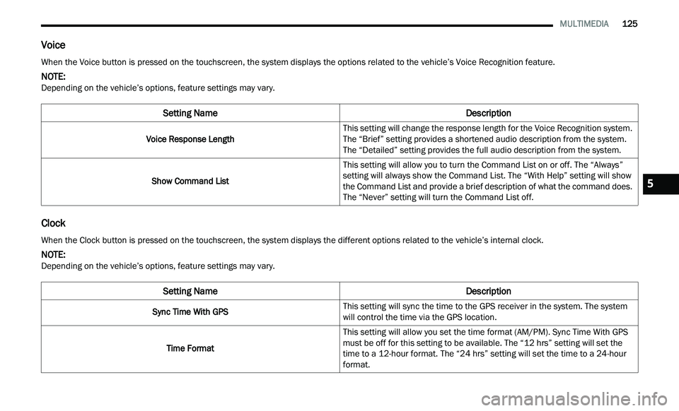
Voice
Clock
When the Voice button is pressed on the touchscreen, the system displays the options related to the vehicle’s Voice Recognition feature.
NOTE:
Depending on the vehicle’s options, feature settings may vary.
Setting Name Description
Voice Response LengthThis setting will change the response length for the Voice Recognition system.
T
h
e “Brief” setting provides a shortened audio description from the system.
The “Detailed” setting provides the full audio description from the system.
Show Command List This setting will allow you to turn the Command List on or off. The “Always”
se
tting will always show the Command List. The “With Help” setting will show
the Command List and provide a brief description of what the command does.
The “Never” setting will turn the Command List off.
When the Clock button is pressed on the touchscreen, the system displays the different options related to the vehicle’s internal clock.
NOTE:
Depending on the vehicle’s options, feature settings may vary.
Setting Name Description
Sync Time With GPSThis setting will sync the time to the GPS receiver in the system. The system
w
i
ll control the time via the GPS location.
Time Format This setting will allow you set the time format (AM/PM). Sync Time With GPS
m
u
st be off for this setting to be available. The “12 hrs” setting will set the
time to a 12-hour format. The “24 hrs” setting will set the time to a 24-hour
format.
5
Page 185 of 268
IN CASE OF EMERGENCY 183
3. Apply the parking brake.
4. P lace the gear selector into PARK (P).
5
. T urn the ignition to the OFF position.
6
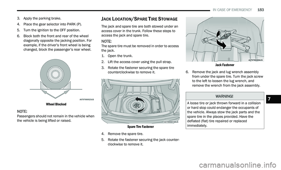
. B lock both the front and rear of the wheel
d
iagonally opposite the jacking position. For
example, if the driver’s front wheel is being
changed, block the passenger’s rear wheel.
Wheel Blocked
NOTE:
Passengers should not remain in the vehicle when
t h
e vehicle is being lifted or raised.
JACK LOCATION/SPARE TIRE STOWAGE
The jack and spare tire are both stowed under an
access cover in the trunk. Follow these steps to
access the jack and spare tire.
NOTE:
The spare tire must be removed in order to access
t h
e jack.
1. Open the trunk.
2
. Li ft the access cover using the pull strap.
3
. R otate the fastener securing the spare tire
c
ounterclockwise to remove it.
Spare Tire Fastener
4. R emove the spare tire.
5
. R otate the fastener securing the jack counter -
c
lockwise to remove it.
Jack Fastener
6. R emove the jack and lug wrench assembly
f
rom under the spare tire. Turn the jack screw
to the left to loosen the lug wrench, and
remove the wrench from the jack assembly.
WARNING!
A loose tire or jack thrown forward in a collision
or hard stop could endanger the occupants of
the vehicle. Always stow the jack parts and the
spare tire in the places provided. Have the
deflated (flat) tire repaired or replaced
immediately.7
Page 186 of 268
184 IN CASE OF EMERGENCY
(Continued)
JACKING AND CHANGING A TIRE
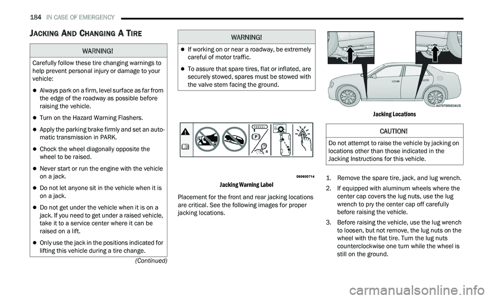
Jacking Warning Label
Placement for the front and rear jacking locations
ar
e critical. See the following images for proper
jacking locations.
Jacking Locations
1. R emove the spare tire, jack, and lug wrench.
2
. I f equipped with aluminum wheels where the
c
enter cap covers the lug nuts, use the lug
wrench to pry the center cap off carefully
before raising the vehicle.
3. Before raising the vehicle, use the lug wrench t
o loosen, but not remove, the lug nuts on the
wheel with the flat tire. Turn the lug nuts
counterclockwise one turn while the wheel is
still on the ground.
WARNING!
Carefully follow these tire changing warnings to
help prevent personal injury or damage to your
vehicle:
Always park on a firm, level surface as far from
the edge of the roadway as possible before
raising the vehicle.
Turn on the Hazard Warning Flashers.
Apply the parking brake firmly and set an auto -
matic transmission in PARK.
Chock the wheel diagonally opposite the
wheel to be raised.
Never start or run the engine with the vehicle
on a jack.
Do not let anyone sit in the vehicle when it is
on a jack.
Do not get under the vehicle when it is on a
jack. If you need to get under a raised vehicle,
take it to a service center where it can be
raised on a lift.
Only use the jack in the positions indicated for
lifting this vehicle during a tire change.
If working on or near a roadway, be extremely
careful of motor traffic.
To assure that spare tires, flat or inflated, are
securely stowed, spares must be stowed with
the valve stem facing the ground.
WARNING!
CAUTION!
Do not attempt to raise the vehicle by jacking on
locations other than those indicated in the
Jacking Instructions for this vehicle.
Page 187 of 268
IN CASE OF EMERGENCY 185
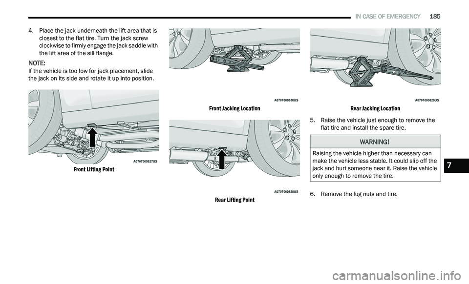
4. Place the jack underneath the lift area that is
closest to the flat tire. Turn the jack screw
clockwise to firmly engage the jack saddle with
the lift area of the sill flange.
NOTE:
If the vehicle is too low for jack placement, slide
t h
e jack on its side and rotate it up into position.
Front Lifting Point Front Jacking Location
Rear Lifting Point Rear Jacking Location
5. R aise the vehicle just enough to remove the
f
lat tire and install the spare tire.
6. R emove the lug nuts and tire.
WARNING!
Raising the vehicle higher than necessary can
make the vehicle less stable. It could slip off the
jack and hurt someone near it. Raise the vehicle
only enough to remove the tire.
7