2021 CHRYSLER 300 ad blue
[x] Cancel search: ad bluePage 5 of 268

3
EXTERIOR LIGHTS ................................................. 40
Headlight Switch.. .............................................40
Multifunction Lever . . ........................................40
Daytime Running Lights (DRLs). . .....................41
High/Low Beam Switch. . ..................................41
Automatic High Beam — If Equipped . . ...........41
Flash-To-Pass. . ..................................................41
Automatic Headlights . . ....................................41
Parking Lights . . ................................................41
Headlights On With Wipers . . ............................42
Adaptive Bi-Xenon High Intensity Discharge
Headlights — If Equipped . .
...............................42
Headlight Time Delay . . .....................................42
Lights-On Reminder . . .......................................42
Fog Lights — If Equipped . . ................................42
Turn Signals . . ....................................................43
Lane Change Assist — If Equipped . . ................43
INTERIOR LIGHTS . . ............................................... 43
Interior Courtesy Lights .. ..................................43
WINDSHIELD WIPERS AND WASHERS . . ............ 45
Windshield Wiper Operation .. ..........................45
Rain Sensing Wipers — If Equipped . . .............46
CLIMATE CONTROLS . . .......................................... 47
Automatic Climate Control Descriptions And
Functions . .........................................................47
A
utomatic Temperature Control (ATC) . . .........49
Climate Voice Commands. . ..............................50
Operating Tips . . ...............................................50 INTERIOR STORAGE AND EQUIPMENT .
.
............. 51
Storage..............................................................51
U SB/AUX Control . . ...........................................53
Lighted Cupholders — If Equipped . . ................53
Heated And Cooled Cupholders —
If Equipped . .
.....................................................53
Power Sunshade — If Equipped . . ....................54
Power Outlets . . .................................................54
WINDOWS . . ............................................................56
Power Window Controls .. .................................56
Automatic Window Features . . ........................56
Reset Auto-Up . . ................................................57
Window Lockout Switch . . .................................57
Wind Buffeting . . ...............................................57
PANORAMIC SUNROOF — IF EQUIPPED . . ...........58
Opening And Closing The Sunroof.. .................58
Pinch Protect Feature . . ....................................58
Venting Sunroof. . ..............................................59
Opening And Closing The Power Shade. . ........59
Sunroof Maintenance . . ....................................59
Ignition Off Operation. . .....................................59
HOOD . .....................................................................59
O pening The Hood.. ..........................................59
Closing The Hood . . ...........................................60
TRUNK . ...................................................................60
O pening The Trunk .. .........................................60
Closing The Trunk. . ...........................................60
Trunk Safety . . ...................................................61
Cargo Area Features . . .....................................61
LOAD LEVELING SYSTEM — IF EQUIPPED . . .......63
GETTING TO KNOW YOUR
INSTRUMENT PANEL
INSTRUMENT CLUSTER ........................................ 64
Instrument Cluster Descriptions .. .................. 66
INSTRUMENT CLUSTER DISPLAY . . ...................... 66
Location And Controls.. .................................... 66
Engine Oil Life Reset . . ..................................... 67
Instrument Cluster Display Selectable
Menu Items . .
.................................................... 68
Battery Saver On/Battery Saver Mode
Message — Electrical Load Reduction
Actions — If Equipped . .
.................................... 70
Programmable Features . . ................................ 71
WARNING LIGHTS AND MESSAGES . . ................. 71
Red Warning Lights .. ........................................72
Yellow Warning Lights . . .................................... 74
Yellow Indicator Lights . . ................................... 77
Green Indicator Lights . . ................................... 77
White Indicator Lights . . .................................... 78
Blue Indicator Lights . . ...................................... 78
ONBOARD DIAGNOSTIC SYSTEM — OBD II . . ...... 79
Onboard Diagnostic System
(OBD II) Cybersecurity . .
.................................... 79
EMISSIONS INSPECTION AND MAINTENANCE
PROGRAMS . .
.......................................................... 79
Page 13 of 268
11
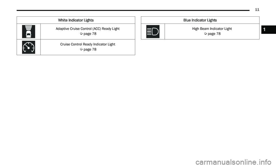
White Indicator Lights
Adaptive Cruise Control (ACC) Ready Light
Ú page 78
Cruise Control Ready Indicator Light
Ú page 78
Blue Indicator Lights
High Beam Indicator Light
Ú page 781
Page 50 of 268
48 GETTING TO KNOW YOUR VEHICLE
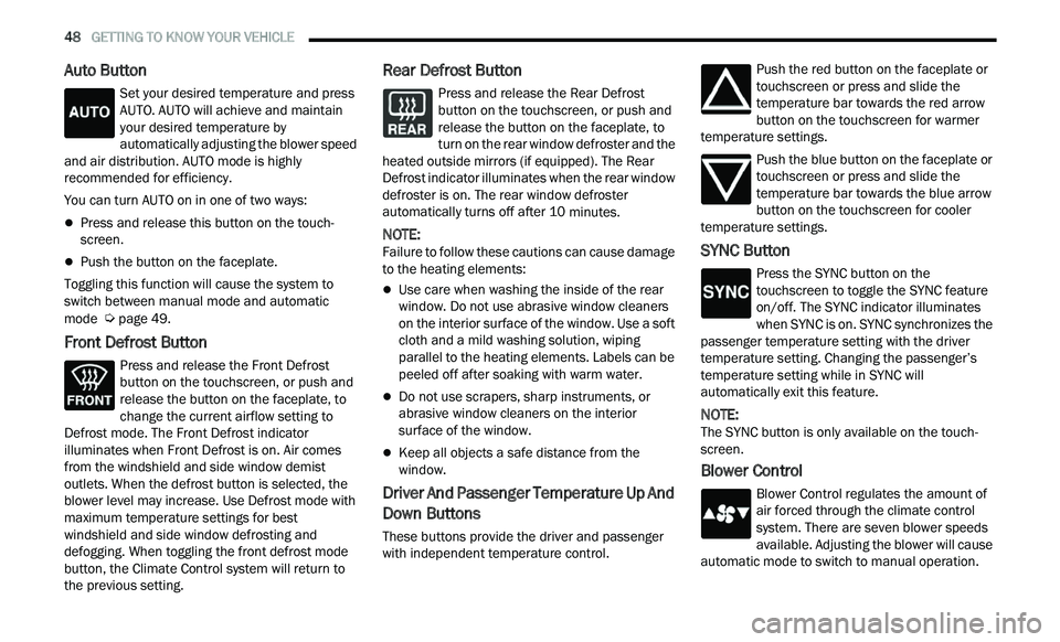
Auto Button
Set your desired temperature and press
AUTO. AUTO will achieve and maintain
you
r desired temperature by
automatically adjusting the blower speed
and air distribution. AUTO mode is highly
recommended for efficiency.
You can turn AUTO on in one of two ways:
Press and release this button on the touch -
screen.
Push the button on the faceplate.
Toggling this function will cause the system to
s w
itch between manual mode and automatic
mode
Ú page 49.
Front Defrost Button
Press and release the Front Defrost
button on the touchscreen, or push and
re
lease the button on the faceplate, to
change the current airflow setting to
Defrost mode. The Front Defrost indicator
illuminates when Front Defrost is on. Air comes
from the windshield and side window demist
outlets. When the defrost button is selected, the
blower level may increase. Use Defrost mode with
maximum temperature settings for best
windshield and side window defrosting and
defogging. When toggling the front defrost mode
button, the Climate Control system will return to
the previous setting.
Rear Defrost Button
Press and release the Rear Defrost
button on the touchscreen, or push and
r e
lease the button on the faceplate, to
turn on the rear window defroster and the
heated outside mirrors (if equipped). The Rear
Defrost indicator illuminates when the rear window
defroster is on. The rear window defroster
automatically turns off after 10 minutes.
NOTE:
Failure to follow these cautions can cause damage
t o
the heating elements:
Use care when washing the inside of the rear
window. Do not use abrasive window cleaners
on the interior surface of the window. Use a soft
cloth and a mild washing solution, wiping
parallel to the heating elements. Labels can be
peeled off after soaking with warm water.
Do not use scrapers, sharp instruments, or
abrasive window cleaners on the interior
surface of the window.
Keep all objects a safe distance from the
window.
Driver And Passenger Temperature Up And
Down Buttons
These buttons provide the driver and passenger
with independent temperature control. Push the red button on the faceplate or
touchscreen or press and slide the
t
e
mperature bar towards the red arrow
button on the touchscreen for warmer
temperature settings.
Push the blue button on the faceplate or
touchscreen or press and slide the
te
mperature bar towards the blue arrow
button on the touchscreen for cooler
temperature settings.
SYNC Button
Press the SYNC button on the
touchscreen to toggle the SYNC feature
o n
/off. The SYNC indicator illuminates
when SYNC is on. SYNC synchronizes the
passenger temperature setting with the driver
temperature setting. Changing the passenger’s
temperature setting while in SYNC will
automatically exit this feature.
NOTE:
The SYNC button is only available on the touch-
screen.
Blower Control
Blower Control regulates the amount of
air forced through the climate control
s y
stem. There are seven blower speeds
available. Adjusting the blower will cause
automatic mode to switch to manual operation.
Page 80 of 268

78 GETTING TO KNOW YOUR INSTRUMENT PANEL
LaneSense Indicator Light — If Equipped
The LaneSense indicator light illuminates
solid green when both lane markings
ha
ve been detected and the system is
“armed” and ready to provide visual and
torque warnings if an unintentional lane departure
occurs
Ú page 108.
Parking/Headlights On Indicator Light
This indicator light will illuminate when
the parking lights or headlights are
tu
rned on Ú page 40.
Sport Mode Indicator Light
This light will turn on when Sport Mode is
active.
Turn Signal Indicator Lights
When the left or right turn signal is
activated, the turn signal indicator will
f
l
ash independently and the
corresponding exterior turn signal lamps
will flash. Turn signals can be activated when the
multifunction lever is moved down (left) or up
(right).
NOTE:
A continuous chime will sound if the vehicle is
driven more than 1 mile (1.6 km) with either
t u
rn signal on.
Check for an inoperative outside light bulb if
either indicator flashes at a rapid rate.
ECO Mode Indicator Light — If Equipped
This light will turn on when ECO mode is
active.
WHITE INDICATOR LIGHTS
Adaptive Cruise Control (ACC) Ready Light
— If Equipped
This light will turn on when ACC has been
turned on, but is not set Ú page 94.
Cruise Control Ready Indicator Light
This indicator light will illuminate when
the cruise control is ready, but not set
Ú page 92.
LaneSense Indicator Light — If Equipped
When the LaneSense system is ON, but
not armed, the LaneSense indicator light
il
luminates solid white. This occurs when
only left, right, or neither lane line has
been detected. If a single lane line is detected, the
system is ready to provide only visual warnings if
an unintentional lane departure occurs on the
detected lane line
Ú page 108.
BLUE INDICATOR LIGHTS
High Beam Indicator Light
This indicator light will illuminate to
indicate that the high beam headlights are
on
. With the low beams activated, push
the multifunction lever forward (toward the
front of the vehicle) to turn on the high beams. Pull
the multifunction lever rearward (toward the rear of
the vehicle) to turn off the high beams. If the high
beams are off, pull the lever toward you for a
temporary high beam on, "flash to pass" scenario.
Page 135 of 268
MULTIMEDIA 133
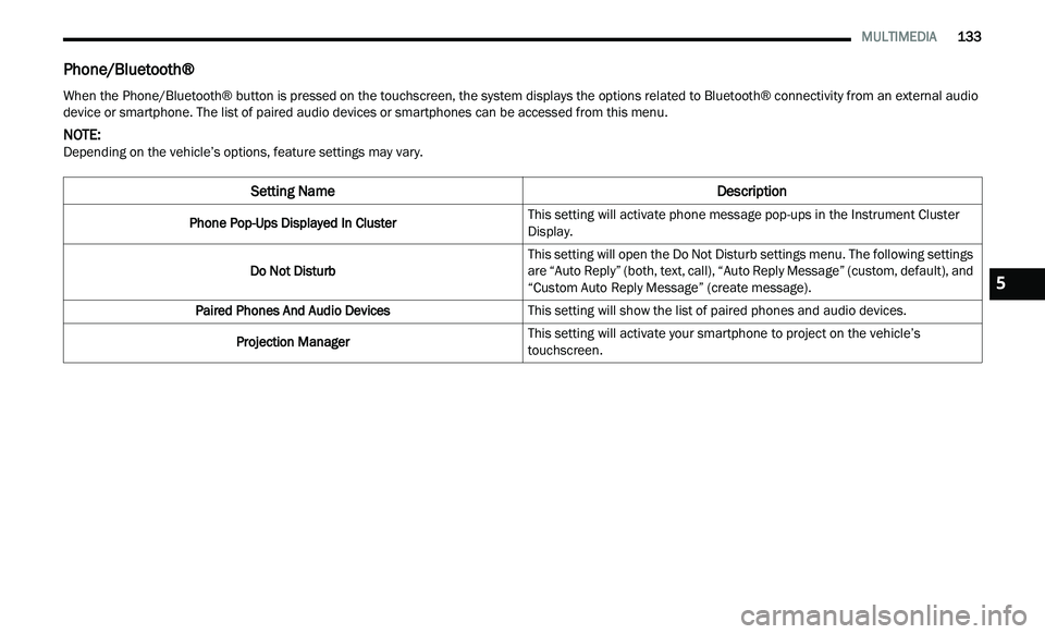
Phone/Bluetooth®
When the Phone/Bluetooth® button is pressed on the touchscreen, the system displays the options related to Bluetooth® connectivity from an external audio
device or smartphone. The list of paired audio devices or smartphones can be accessed from this menu.
NOTE:
Depending on the vehicle’s options, feature settings may vary.
Setting Name Description
Phone Pop-Ups Displayed In ClusterThis setting will activate phone message pop-ups in the Instrument Cluster
D
i
splay.
Do Not Disturb This setting will open the Do Not Disturb settings menu. The following settings
a
r
e “Auto Reply” (both, text, call), “Auto Reply Message” (custom, default), and
“Custom Auto Reply Message” (create message).
Paired Phones And Audio Devices This setting will show the list of paired phones and audio devices.
Projection Manager This setting will activate your smartphone to project on the vehicle’s
tou
chscreen.
5
Page 137 of 268
MULTIMEDIA 135
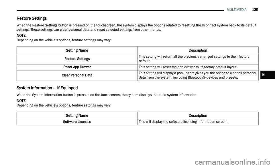
Restore Settings
System Information — If Equipped
When the Restore Settings button is pressed on the touchscreen, the system displays the options related to resetting the Uconnect system back to its default
settings. These settings can clear personal data and reset selected settings from other menus.
NOTE:
Depending on the vehicle’s options, feature settings may vary.
Setting Name Description
Restore SettingsThis setting will return all the previously changed settings to their factory
d
e
fault.
Reset App Drawer This setting will reset the app drawer to its factory default layout.
Clear Personal Data This setting will display a pop-up that gives you the option to clear all personal
d
a
ta from the system, including Bluetooth® devices and presets.
When the System Information button is pressed on the touchscreen, the system displays the radio system information.
NOTE:
Depending on the vehicle’s options, feature settings may vary.
Setting Name Description
Software LicensesThis will display the software licensing information screen.
5
Page 217 of 268
SERVICING AND MAINTENANCE 215
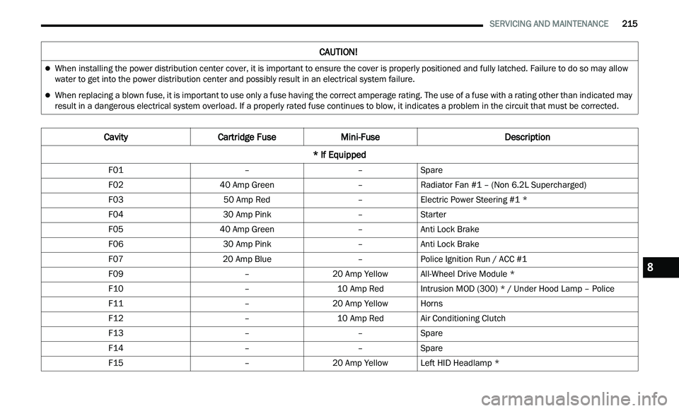
CAUTION!
When installing the power distribution center cover, it is important to ensure the cover is properly positioned and fully latched. Failure to do so may allow
water to get into the power distribution center and possibly result in an electrical system failure.
When replacing a blown fuse, it is important to use only a fuse having the correct amperage rating. The use of a fuse with a rating other than indicated may
result in a dangerous electrical system overload. If a properly rated fuse continues to blow, it indicates a problem in the circuit that must be corrected.
Cavity Cartridge Fuse Mini-Fuse Description
* If Equipped
F01 ––Spare
F02 40 Amp Green –Radiator Fan #1 – (Non 6.2L Supercharged)
F03 50 Amp Red –Electric Power Steering #1 *
F04 30 Amp Pink –Starter
F05 40 Amp Green –Anti Lock Brake
F06 30 Amp Pink –Anti Lock Brake
F07 20 Amp Blue –Police Ignition Run / ACC #1
F09 –20 Amp YellowAll-Wheel Drive Module *
F10 –10 Amp RedIntrusion MOD (300) * / Under Hood Lamp – Police
F11 –20 Amp YellowHorns
F12 –10 Amp RedAir Conditioning Clutch
F13 ––Spare
F14 ––Spare
F15 –20 Amp YellowLeft HID Headlamp *
8
Page 218 of 268
216 SERVICING AND MAINTENANCE
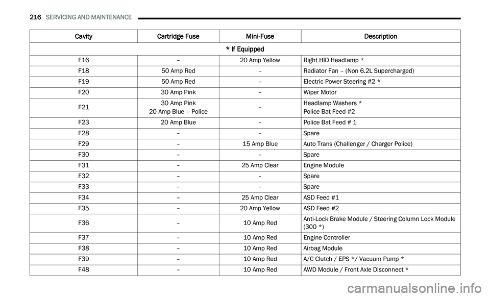
F16 –20 Amp YellowRight HID Headlamp *
F18 50 Amp Red –Radiator Fan – (Non 6.2L Supercharged)
F19 50 Amp Red –Electric Power Steering #2 *
F20 30 Amp Pink –Wiper Motor
F21 30 Amp Pink
20 Amp Blue – Police –Headlamp Washers *
Police Bat Feed #2
F23 20 Amp Blue –Police Bat Feed # 1
F28 ––Spare
F29 –15 Amp BlueAuto Trans (Challenger / Charger Police)
F30 ––Spare
F31 –25 Amp ClearEngine Module
F32 ––Spare
F33 ––Spare
F34 –25 Amp ClearASD Feed #1
F35 –20 Amp YellowASD Feed #2
F36 –10 Amp RedAnti-Lock Brake Module / Steering Column Lock Module
(
3
00 *)
F37 –10 Amp RedEngine Controller
F38 –10 Amp RedAirbag Module
F39 –10 Amp RedA/C Clutch / EPS */ Vacuum Pump *
F48 –10 Amp RedAWD Module / Front Axle Disconnect *
Cavity Cartridge Fuse Mini-Fuse Description
* If Equipped