2021 CHRYSLER 300 battery location
[x] Cancel search: battery locationPage 5 of 268

3
EXTERIOR LIGHTS ................................................. 40
Headlight Switch.. .............................................40
Multifunction Lever . . ........................................40
Daytime Running Lights (DRLs). . .....................41
High/Low Beam Switch. . ..................................41
Automatic High Beam — If Equipped . . ...........41
Flash-To-Pass. . ..................................................41
Automatic Headlights . . ....................................41
Parking Lights . . ................................................41
Headlights On With Wipers . . ............................42
Adaptive Bi-Xenon High Intensity Discharge
Headlights — If Equipped . .
...............................42
Headlight Time Delay . . .....................................42
Lights-On Reminder . . .......................................42
Fog Lights — If Equipped . . ................................42
Turn Signals . . ....................................................43
Lane Change Assist — If Equipped . . ................43
INTERIOR LIGHTS . . ............................................... 43
Interior Courtesy Lights .. ..................................43
WINDSHIELD WIPERS AND WASHERS . . ............ 45
Windshield Wiper Operation .. ..........................45
Rain Sensing Wipers — If Equipped . . .............46
CLIMATE CONTROLS . . .......................................... 47
Automatic Climate Control Descriptions And
Functions . .........................................................47
A
utomatic Temperature Control (ATC) . . .........49
Climate Voice Commands. . ..............................50
Operating Tips . . ...............................................50 INTERIOR STORAGE AND EQUIPMENT .
.
............. 51
Storage..............................................................51
U SB/AUX Control . . ...........................................53
Lighted Cupholders — If Equipped . . ................53
Heated And Cooled Cupholders —
If Equipped . .
.....................................................53
Power Sunshade — If Equipped . . ....................54
Power Outlets . . .................................................54
WINDOWS . . ............................................................56
Power Window Controls .. .................................56
Automatic Window Features . . ........................56
Reset Auto-Up . . ................................................57
Window Lockout Switch . . .................................57
Wind Buffeting . . ...............................................57
PANORAMIC SUNROOF — IF EQUIPPED . . ...........58
Opening And Closing The Sunroof.. .................58
Pinch Protect Feature . . ....................................58
Venting Sunroof. . ..............................................59
Opening And Closing The Power Shade. . ........59
Sunroof Maintenance . . ....................................59
Ignition Off Operation. . .....................................59
HOOD . .....................................................................59
O pening The Hood.. ..........................................59
Closing The Hood . . ...........................................60
TRUNK . ...................................................................60
O pening The Trunk .. .........................................60
Closing The Trunk. . ...........................................60
Trunk Safety . . ...................................................61
Cargo Area Features . . .....................................61
LOAD LEVELING SYSTEM — IF EQUIPPED . . .......63
GETTING TO KNOW YOUR
INSTRUMENT PANEL
INSTRUMENT CLUSTER ........................................ 64
Instrument Cluster Descriptions .. .................. 66
INSTRUMENT CLUSTER DISPLAY . . ...................... 66
Location And Controls.. .................................... 66
Engine Oil Life Reset . . ..................................... 67
Instrument Cluster Display Selectable
Menu Items . .
.................................................... 68
Battery Saver On/Battery Saver Mode
Message — Electrical Load Reduction
Actions — If Equipped . .
.................................... 70
Programmable Features . . ................................ 71
WARNING LIGHTS AND MESSAGES . . ................. 71
Red Warning Lights .. ........................................72
Yellow Warning Lights . . .................................... 74
Yellow Indicator Lights . . ................................... 77
Green Indicator Lights . . ................................... 77
White Indicator Lights . . .................................... 78
Blue Indicator Lights . . ...................................... 78
ONBOARD DIAGNOSTIC SYSTEM — OBD II . . ...... 79
Onboard Diagnostic System
(OBD II) Cybersecurity . .
.................................... 79
EMISSIONS INSPECTION AND MAINTENANCE
PROGRAMS . .
.......................................................... 79
Page 7 of 268

5
SAFETY
SAFETY FEATURES .............................................. 137
Anti-Lock Brake System (ABS) .. ................... 137
Electronic Brake Control (EBC) System . . ..... 138
AUXILIARY DRIVING SYSTEMS . . ........................ 142
Blind Spot Monitoring (BSM) —
If Equipped. .
................................................... 142
Forward Collision Warning (FCW) With
Mitigation Operation — If Equipped. .
............ 146
Tire Pressure Monitoring System (TPMS) . . .. 148
OCCUPANT RESTRAINT SYSTEMS . . .................. 151
Occupant Restraint Systems Features .. ..... 151
Important Safety Precautions. . ..................... 152
Seat Belt Systems . . ...................................... 152
Supplemental Restraint Systems (SRS) . . .... 158
Child Restraints . . ........................................... 166
SAFETY TIPS . . ....................................................... 176
Transporting Passengers .. ............................ 176
Transporting Pets . . ........................................ 176
Safety Checks You Should Make Inside
The Vehicle . .
................................................. 176
Periodic Safety Checks You Should Make
Outside The Vehicle . .
.................................... 177
Exhaust Gas . . ................................................ 178
Carbon Monoxide Warnings . . ....................... 178
IN CASE OF EMERGENCY
HAZARD WARNING FLASHERS......................... 179
ASSIST AND SOS MIRROR — IF EQUIPPED .. ... 179
JACKING AND TIRE CHANGING .. ....................... 182
Preparations For Jacking .. ........................... 182
Jack Location/Spare Tire Stowage . . ............ 183
Jacking And Changing A Tire . . ..................... 184
JUMP STARTING . . ............................................... 186
Preparations For Jump Start .. ...................... 187
Jump Starting Procedure . . ............................ 188
REFUELING IN AN EMERGENCY –
IF EQUIPPED . .
..................................................... 189
IF YOUR ENGINE OVERHEATS .. ........................ 190
MANUAL PARK RELEASE .. ................................ 190
FREEING A STUCK VEHICLE .. ............................ 192
TOWING A DISABLED VEHICLE .. ....................... 193
All Wheel Drive (AWD) Models .. .................... 194
Rear Wheel Drive (RWD) Models . . ............... 194
ENHANCED ACCIDENT RESPONSE SYSTEM
(EARS) . ................................................................. 194
E
VENT DATA RECORDER (EDR) .. ...................... 194
SERVICING AND MAINTENANCE
SCHEDULED SERVICING ................................... 195
Maintenance Plan .. ....................................... 196
ENGINE COMPARTMENT . . .................................. 199
3.6L Engine .. ................................................ 199
5.7L Engine . . ................................................ 200
Checking Oil Level . . ....................................... 201 Adding Washer Fluid .
.
................................... 201
Maintenance-Free Battery . . ......................... 201
Pressure Washing . . ....................................... 202
VEHICLE MAINTENANCE . . .................................. 202
Engine Oil ...................................................... 202
E ngine Oil Filter . . ........................................... 203
Engine Air Cleaner Filter . . ............................. 203
Air Conditioner Maintenance. . ...................... 204
Accessory Drive Belt Inspection . . ................. 205
Body Lubrication . . ......................................... 206
Windshield Wiper Blades. . ............................ 206
Exhaust System . . ........................................... 208
Cooling System . . ........................................... 209
Brake System . . ............................................. 212
Automatic Transmission . . ............................ 212
All Wheel Drive (AWD) — If Equipped . . ........ 213
Rear Axle. ....................................................... 213
F uses. ............................................................. 214
B ulb Replacement . . ...................................... 221
TIRES . .................................................................... 225
T ire Safety Information .. ............................... 225
Tires — General Information . . ...................... 232
Tire Types. ...................................................... 235
S pare Tires — If Equipped. . ........................... 236
Wheel And Wheel Trim Care. . ....................... 238
Snow Traction Devices. . ................................ 239
Tire Rotation Recommendations . . .............. 240
Page 57 of 268
GETTING TO KNOW YOUR VEHICLE 55
NOTE:
All accessories connected to the “battery” powered
ou t
lets should be removed or turned off when the
vehicle is not in use to protect the battery against
discharge.
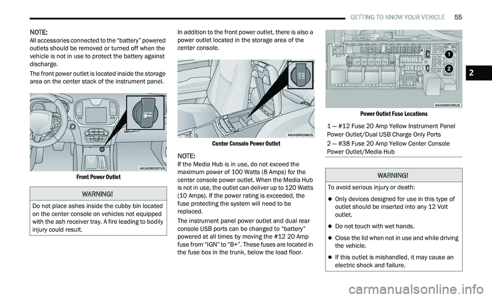
The front power outlet is located inside the storage
ar
ea on the center stack of the instrument panel.
Front Power Outlet
In addition to the front power outlet, there is also a
p
ow
er outlet located in the storage area of the
center console.
Center Console Power Outlet
NOTE:
If the Media Hub is in use, do not exceed the
m a
ximum power of 100 Watts (8 Amps) for the
center console power outlet. When the Media Hub
is not in use, the outlet can deliver up to 120 Watts
(10 Amps). If the power rating is exceeded, the
fuse protecting the system will need to be
replaced.
The instrument panel power outlet and dual rear
c on
sole USB ports can be changed to “battery”
powered at all times by moving the #12 20 Amp
fuse from “IGN” to “B+”. These fuses are located in
the fuse box in the trunk, below the load floor.
Power Outlet Fuse Locations
WARNING!
Do not place ashes inside the cubby bin located
on the center console on vehicles not equipped
with the ash receiver tray. A fire leading to bodily
injury could result.
1 — #12 Fuse 20 Amp Yellow Instrument Panel
Power Outlet/Dual USB Charge Only Ports
2 — #38 Fuse 20 Amp Yellow Center Console
Power Outlet/Media Hub
WARNING!
To avoid serious injury or death:
Only devices designed for use in this type of
outlet should be inserted into any 12 Volt
outlet.
Do not touch with wet hands.
Close the lid when not in use and while driving
the vehicle.
If this outlet is mishandled, it may cause an
electric shock and failure.
2
Page 58 of 268

56 GETTING TO KNOW YOUR VEHICLE
WINDOWS
POWER WINDOW CONTROLS
The window controls on the driver's door control all
the door windows.
Power Window Switches
The passenger door windows can also be operated
b y
using the single window controls on the
passenger door trim panel. The window controls
will operate only when the ignition is in the ACC or
ON/RUN position.
NOTE:
The power window switches will remain active for
u p
to 10 minutes after the ignition is placed in the
O F
F position. Opening either front door will cancel
this feature. The timing is programmable within
Uconnect Settings
Ú page 122.
AUTOMATIC WINDOW FEATURES
Auto-Down Feature
The driver and front passenger door power window
sw
itches have an Auto-Down feature. Push the
window switch down to the second detent, release,
and the window will go down automatically.
To stop the window from going all the way down
du
ring the Auto-Down operation, pull up or push
down on the switch briefly.
CAUTION!
Many accessories that can be plugged in draw
power from the vehicle's battery even when
not in use (i.e., cellular phones, etc.). Eventu -
ally, if plugged in long enough, the vehicle's
b a
ttery will discharge sufficiently to degrade
battery life and/or prevent the engine from
starting.
Accessories that draw higher power (i.e.,
coolers, vacuum cleaners, lights, etc.) will
degrade the battery even more quickly. Only
use these intermittently and with greater
caution.
After the use of high power draw accessories
or long periods of the vehicle not being started
(with accessories still plugged in), the vehicle
must be driven a sufficient length of time to
allow the alternator to recharge the vehicle's
battery.
Power outlets are designed for accessory
plugs only. Do not hang any type of accessory
or accessory bracket from the plug. Improper
use of the power outlet can cause damage.
WARNING!
Never leave children unattended in a vehicle, and
do not let children play with power windows. Do
not leave the key fob in or near the vehicle, or in a
location accessible to children, and do not leave
the ignition of a vehicle equipped with Keyless
Enter ‘n Go™ in the ACC or ON/RUN position.
Occupants, particularly unattended children, can
become entrapped by the windows while operat -
ing the power window switches. Such entrapment
m a
y result in serious injury or death.
Page 161 of 268
SAFETY 159
The ORC contains a backup power supply system
that may deploy the air bag system even if the
battery loses power or it becomes disconnected
prior to deployment.
The ORC turns on the Air Bag Warning Light in the
in
strument panel for approximately four to eight
seconds for a self-check when the ignition switch is
first in the ON/RUN position. After the self-check,
the Air Bag Warning Light will turn off. If the ORC
detects a malfunction in any part of the system, it
turns on the Air Bag Warning Light, either
momentarily or continuously. A single chime will
sound to alert you if the light comes on again after
initial startup.
The ORC also includes diagnostics that will
i l
luminate the instrument panel Air Bag Warning
Light if a malfunction is detected that could affect
the air bag system. The diagnostics also record the
nature of the malfunction. While the air bag system
is designed to be maintenance free, if any of the
following occurs, have an authorized dealer
service the air bag system immediately.
The Air Bag Warning Light does not come on
during the four to eight seconds when the igni -
tion switch is first in the ON/RUN position.
The Air Bag Warning Light remains on after the
four to eight-second interval.
The Air Bag Warning Light comes on intermit -
tently or remains on while driving.
NOTE:
If the speedometer, tachometer, or any engine
r e
lated gauges are not working, the Occupant
Restraint Controller (ORC) may also be disabled. In
this condition the air bags may not be ready to
inflate for your protection. Have an authorized
dealer service the air bag system immediately.
Redundant Air Bag Warning Light
If a fault with the Air Bag Warning Light is
detected, which could affect the
S u
pplemental Restraint System (SRS),
the Redundant Air Bag Warning Light will
illuminate on the instrument panel. The
Redundant Air Bag Warning Light will stay on until
the fault is cleared. In addition, a single chime will
sound to alert you that the Redundant Air Bag
Warning Light has come on and a fault has been
detected. If the Redundant Air Bag Warning Light comes on intermittently or remains on while driving
have an authorized dealer service the vehicle
immediately
Ú page 71.
Front Air Bags
This vehicle has front air bags and lap/shoulder
belts for both the driver and front passenger. The
front air bags are a supplement to the seat belt
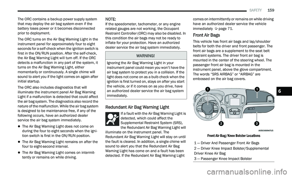
restraint systems. The driver front air bag is
mounted in the center of the steering wheel. The
passenger front air bag is mounted in the
instrument panel, above the glove compartment.
The words “SRS AIRBAG” or “AIRBAG” are
embossed on the air bag covers.
Front Air Bag/Knee Bolster Locations
WARNING!
Ignoring the Air Bag Warning Light in your
instrument panel could mean you won’t have the
air bag system to protect you in a collision. If the
light does not come on as a bulb check when the
ignition is first turned on, stays on after you start
the vehicle, or if it comes on as you drive, have
an authorized dealer service the air bag system
immediately.
1 — Driver And Passenger Front Air Bags
2 — Driver Knee Impact Bolster/Supplemental
Driver Knee Air Bag
3 — Passenger Knee Impact Bolster
6
Page 167 of 268
SAFETY 165
NOTE:
After an accident, remember to cycle the ignition to
t h
e STOP (OFF/LOCK) position and remove the key
from the ignition switch to avoid draining the
battery. Carefully check the vehicle for fuel leaks in
the engine compartment and on the ground near
the engine compartment and fuel tank before
resetting the system and starting the engine. If
there are no fuel leaks or damage to the vehicle
electrical devices (e.g. headlights) after an
accident, reset the system by following the
procedure described below. If you have any doubt,
contact an authorized dealer.
Enhanced Accident Response System
Reset Procedure
In order to reset the Enhanced Accident Response
System functions after an event, the ignition switch
must be changed from ignition START or ON/RUN
to ignition OFF. Carefully check the vehicle for fuel
leaks in the engine compartment and on the
ground near the engine compartment and fuel
tank before resetting the system and starting the
engine.
After an accident, if the vehicle will not start after
p e
rforming the reset procedure, the vehicle must
be towed to an authorized dealer to be inspected
and to have the Enhanced Accident Response
System reset.
Maintaining Your Air Bag System Event Data Recorder (EDR)
This vehicle is equipped with an event data
recorder (EDR). The main purpose of an EDR is to
record, in certain crash or near crash-like
situations, such as an air bag deployment or hitting
a road obstacle, data that will assist in
understanding how a vehicle’s systems performed.
The EDR is designed to record data related to
vehicle dynamics and safety systems for a short
period of time, typically 30 seconds or less. The
EDR in this vehicle is designed to record such data
as:
How various systems in your vehicle were oper -
ating;
Whether or not the driver and passenger safety
belts were buckled/fastened;
How far (if at all) the driver was depressing the
accelerator and/or brake pedal; and,
How fast the vehicle was traveling.
These data can help provide a better
u n
derstanding of the circumstances in which
crashes and injuries occur.
NOTE:
EDR data are recorded by your vehicle only if a
n on
-trivial crash situation occurs; no data are
recorded by the EDR under normal driving condi -
tions and no personal data (e.g., name, gender,
a g
e, and crash location) are recorded. However,
other parties, such as law enforcement, could
WARNING!
Modifications to any part of the air bag system
could cause it to fail when you need it. You
could be injured if the air bag system is not
there to protect you. Do not modify the compo -
nents or wiring, including adding any kind of
ba
dges or stickers to the steering wheel hub
trim cover or the upper passenger side of the
instrument panel. Do not modify the front
fascia/bumper, vehicle body structure, or add
aftermarket side steps or running boards.
It is dangerous to try to repair any part of the
air bag system yourself. Be sure to tell anyone
who works on your vehicle that it has an air
bag system.
Do not attempt to modify any part of your air
bag system. The air bag may inflate accidentally
or may not function properly if modifications are
made. Take your vehicle to an authorized dealer
for any air bag system service. If your seat,
including your trim cover and cushion, needs to
be serviced in any way (including removal or
loosening/tightening of seat attachment bolts),
take the vehicle to an authorized dealer. Only
manufacturer approved seat accessories may
be used. If it is necessary to modify the air bag
system for persons with disabilities, contact an
authorized dealer.
6
Page 189 of 268
IN CASE OF EMERGENCY 187
PREPARATIONS FOR JUMP START
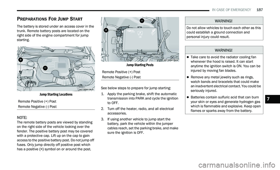
The battery is stored under an access cover in the
trunk. Remote battery posts are located on the
right side of the engine compartment for jump
starting.
Jump Starting Locations
NOTE:
The remote battery posts are viewed by standing
on
the right side of the vehicle looking over the
fender. The positive battery post may be covered
with a protective cap. Lift up on the cap to gain
access to the positive battery post. Do not jump off
fuses. Only jump directly off positive post which
has a positive (+) symbol on or around the post.
Jump Starting Posts
See below steps to prepare for jump starting:
1. Apply the parking brake, shift the automatic t
ransmission into PARK and cycle the ignition
to OFF.
2. T urn off the heater, radio, and all electrical
a
ccessories.
3. If using another vehicle to jump start the b
attery, park the vehicle within the jumper
cables reach, set the parking brake, and make
sure the ignition is OFF.
Remote Positive (+) Post
Remote Negative (-) Post
Remote Positive (+) Post
Remote Negative (-) Post
WARNING!
Do not allow vehicles to touch each other as this
could establish a ground connection and
personal injury could result.
WARNING!
Take care to avoid the radiator cooling fan
whenever the hood is raised. It can start
anytime the ignition switch is ON. You can be
injured by moving fan blades.
Remove any metal jewelry such as rings,
watch bands and bracelets that could make
an inadvertent electrical contact. You could be
seriously injured.
Batteries contain sulfuric acid that can burn
your skin or eyes and generate hydrogen gas
which is flammable and explosive. Keep open
flames or sparks away from the battery.7
Page 216 of 268
214 SERVICING AND MAINTENANCE
FUSES
General Information
The fuses protect electrical systems against
excessive current.
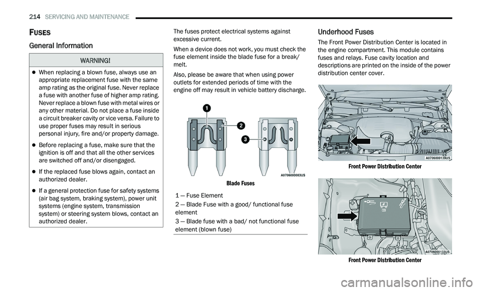
When a device does not work, you must check the
fu
se element inside the blade fuse for a break/
melt.
Also, please be aware that when using power
ou t
lets for extended periods of time with the
engine off may result in vehicle battery discharge.
Blade Fuses
Underhood Fuses
The Front Power Distribution Center is located in
the engine compartment. This module contains
fuses and relays. Fuse cavity location and
descriptions are printed on the inside of the power
distribution center cover.
Front Power Distribution Center
Front Power Distribution Center
WARNING!
When replacing a blown fuse, always use an
appropriate replacement fuse with the same
amp rating as the original fuse. Never replace
a fuse with another fuse of higher amp rating.
Never replace a blown fuse with metal wires or
any other material. Do not place a fuse inside
a circuit breaker cavity or vice versa. Failure to
use proper fuses may result in serious
personal injury, fire and/or property damage.
Before replacing a fuse, make sure that the
ignition is off and that all the other services
are switched off and/or disengaged.
If the replaced fuse blows again, contact an
authorized dealer.
If a general protection fuse for safety systems
(air bag system, braking system), power unit
systems (engine system, transmission
system) or steering system blows, contact an
authorized dealer.1 — Fuse Element
2 — Blade Fuse with a good/ functional fuse
element
3 — Blade fuse with a bad/ not functional fuse
el
ement (blown fuse)