Page 188 of 268

186 IN CASE OF EMERGENCY
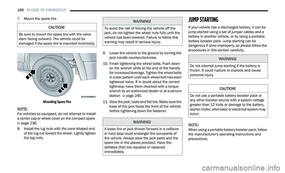
7. Mount the spare tire.
Mounting Spare Tire
NOTE:
For vehicles so equipped, do not attempt to install
a
center cap or wheel cover on the compact spare
Ú page 236.
8. I nstall the lug nuts with the cone shaped end
of
the lug nut toward the wheel. Lightly tighten
the lug nuts. 9. Low
er the vehicle to the ground by turning the
j
ack handle counterclockwise.
10. Finish tightening the wheel bolts. Push down on
the wrench while at the end of the handle
for increased leverage. Tighten the wheel bolts
in a star pattern until each wheel bolt has been
tightened twice. If in doubt about the correct
tightness, have them checked with a torque
wrench by an authorized dealer or at a service
station
Ú page 245.
11. S tow the jack, tools and flat tire. Make sure the
b
ase of the jack faces the front of the vehicle
before tightening down the fastener.
JUMP STARTING
If your vehicle has a discharged battery, it can be
jump started using a set of jumper cables and a
battery in another vehicle, or by using a portable
battery booster pack. Jump starting can be
dangerous if done improperly, so please follow the
procedures in this section carefully.
NOTE:
When using a portable battery booster pack, follow
t h
e manufacturer's operating instructions and
precautions.
CAUTION!
Be sure to mount the spare tire with the valve
stem facing outward. The vehicle could be
damaged if the spare tire is mounted incorrectly.
WARNING!
To avoid the risk of forcing the vehicle off the
jack, do not tighten the wheel nuts fully until the
vehicle has been lowered. Failure to follow this
warning may result in serious injury.
WARNING!
A loose tire or jack thrown forward in a collision
or hard stop could endanger the occupants of
the vehicle. Always stow the jack parts and the
spare tire in the places provided. Have the
deflated (flat) tire repaired or replaced
immediately.
WARNING!
Do not attempt jump starting if the battery is
frozen. It could rupture or explode and cause
personal injury.
CAUTION!
Do not use a portable battery booster pack or
any other booster source with a system voltage
greater than 12 Volts or damage to the battery,
starter motor, alternator or electrical system may
occur.
Page 221 of 268
SERVICING AND MAINTENANCE 219
F23 –10 Amp RedFuel Door * / Diagnostic Port
F24 –10 Amp RedIntegrated Center Stack
F25 –10 Amp RedTire Pressure Monitor System
F26 –15 Amp BlueTrans Mod (Charger Non- Police/300)
F27 –25 Amp ClearAmplifier *
F31 –25 Amp BreakerPower Seats *
F32 –15 Amp BlueHVAC Module/Cluster
F33 –15 Amp BlueIGN SW/Wireless Mod/Steer Clmn Lock Mod/Remote
S
t
art *
F34 –10 Amp RedSteering Column Module/Clock (300)
F35 –5 Amp TanBattery Sensor
F36 –15 Amp BlueActive Exhaust Valve *
F37 –20 Amp YellowRadio
F38 –20 Amp YellowMedia Hub / Console APO
F42 30 Amp Pink –Rear Defrost
F43 –20 Amp YellowRear Heated Seats * / Heated Steering Wheel *
F44 –10 Amp RedPark Assist / Blind Spot / Rear View Camera
F45 –15 Amp BlueCluster / Rearview Mirror / Lane Departure
F46 ––Spare
F47 –10 Amp RedAdaptive Front Lighting / Day Time Running Lamps *
Cavity Cartridge Fuse Mini-Fuse Description
* If Equipped
8
Page 225 of 268

SERVICING AND MAINTENANCE 223
BI-HALOGEN LOW BEAM AND HIGH BEAM
HEADLAMP — IF EQUIPPED
See steps below to replace:
1. O pen the hood.
NOTE:
Removal of the air cleaner filter housing may be
n e
cessary prior to replacing bulbs in the headlamp
assembly on the driver side of the vehicle.
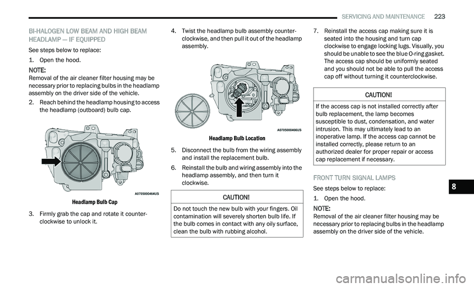
2. R each behind the headlamp housing to access
t
he headlamp (outboard) bulb cap.
Headlamp Bulb Cap
3. F irmly grab the cap and rotate it counter -
c
lockwise to unlock it. 4. Twist the headlamp bulb assembly counter
-
c
lockwise, and then pull it out of the headlamp
a s
sembly.
Headlamp Bulb Location
5. D isconnect the bulb from the wiring assembly
a
nd install the replacement bulb.
6. Reinstall the bulb and wiring assembly into the h
eadlamp assembly, and then turn it
clockwise. 7. Reinstall the access cap making sure it is
s
eated into the housing and turn cap
clockwise to engage locking lugs. Visually, you
should be unable to see the blue O-ring gasket.
The access cap should be uniformly seated
and you should not be able to pull the access
cap off without turning it counterclockwise.
FRONT TURN SIGNAL LAMPS
See steps below to replace:
1. O pen the hood.
NOTE:
Removal of the air cleaner filter housing may be
n e
cessary prior to replacing bulbs in the headlamp
assembly on the driver side of the vehicle.
CAUTION!
Do not touch the new bulb with your fingers. Oil
contamination will severely shorten bulb life. If
the bulb comes in contact with any oily surface,
clean the bulb with rubbing alcohol.
CAUTION!
If the access cap is not installed correctly after
bulb replacement, the lamp becomes
susceptible to dust, condensation, and water
intrusion. This may ultimately lead to an
inoperative lamp. If the access cap cannot be
installed correctly, please return to an
authorized dealer for proper repair or access
cap replacement if necessary.
8
Page 226 of 268

224 SERVICING AND MAINTENANCE
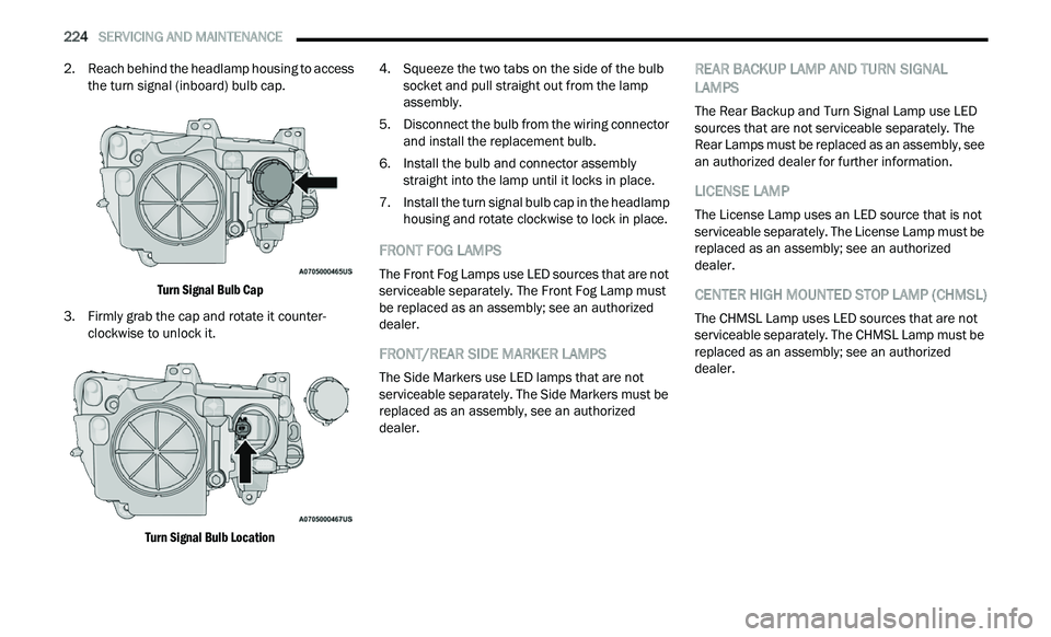
2. Reach behind the headlamp housing to access
the turn signal (inboard) bulb cap.
Turn Signal Bulb Cap
3. F irmly grab the cap and rotate it counter -
c
lockwise to unlock it.
Turn Signal Bulb Location
4. S
queeze the two tabs on the side of the bulb
s
ocket and pull straight out from the lamp
assembly.
5. D isconnect the bulb from the wiring connector
a
nd install the replacement bulb.
6. Install the bulb and connector assembly s
traight into the lamp until it locks in place.
7. Install the turn signal bulb cap in the headlamp h
ousing and rotate clockwise to lock in place.
FRONT FOG LAMPS
The Front Fog Lamps use LED sources that are not
serviceable separately. The Front Fog Lamp must
be replaced as an assembly; see an authorized
dealer.
FRONT/REAR SIDE MARKER LAMPS
The Side Markers use LED lamps that are not
serviceable separately. The Side Markers must be
replaced as an assembly, see an authorized
dealer.
REAR BACKUP LAMP AND TURN SIGNAL
LAMPS
The Rear Backup and Turn Signal Lamp use LED
sources that are not serviceable separately. The
Rear Lamps must be replaced as an assembly, see
an authorized dealer for further information.
LICENSE LAMP
The License Lamp uses an LED source that is not
serviceable separately. The License Lamp must be
replaced as an assembly; see an authorized
dealer.
CENTER HIGH MOUNTED STOP LAMP (CHMSL)
The CHMSL Lamp uses LED sources that are not
serviceable separately. The CHMSL Lamp must be
replaced as an assembly; see an authorized
dealer.