2021 CHRYSLER 300 oil temperature
[x] Cancel search: oil temperaturePage 5 of 268

3
EXTERIOR LIGHTS ................................................. 40
Headlight Switch.. .............................................40
Multifunction Lever . . ........................................40
Daytime Running Lights (DRLs). . .....................41
High/Low Beam Switch. . ..................................41
Automatic High Beam — If Equipped . . ...........41
Flash-To-Pass. . ..................................................41
Automatic Headlights . . ....................................41
Parking Lights . . ................................................41
Headlights On With Wipers . . ............................42
Adaptive Bi-Xenon High Intensity Discharge
Headlights — If Equipped . .
...............................42
Headlight Time Delay . . .....................................42
Lights-On Reminder . . .......................................42
Fog Lights — If Equipped . . ................................42
Turn Signals . . ....................................................43
Lane Change Assist — If Equipped . . ................43
INTERIOR LIGHTS . . ............................................... 43
Interior Courtesy Lights .. ..................................43
WINDSHIELD WIPERS AND WASHERS . . ............ 45
Windshield Wiper Operation .. ..........................45
Rain Sensing Wipers — If Equipped . . .............46
CLIMATE CONTROLS . . .......................................... 47
Automatic Climate Control Descriptions And
Functions . .........................................................47
A
utomatic Temperature Control (ATC) . . .........49
Climate Voice Commands. . ..............................50
Operating Tips . . ...............................................50 INTERIOR STORAGE AND EQUIPMENT .
.
............. 51
Storage..............................................................51
U SB/AUX Control . . ...........................................53
Lighted Cupholders — If Equipped . . ................53
Heated And Cooled Cupholders —
If Equipped . .
.....................................................53
Power Sunshade — If Equipped . . ....................54
Power Outlets . . .................................................54
WINDOWS . . ............................................................56
Power Window Controls .. .................................56
Automatic Window Features . . ........................56
Reset Auto-Up . . ................................................57
Window Lockout Switch . . .................................57
Wind Buffeting . . ...............................................57
PANORAMIC SUNROOF — IF EQUIPPED . . ...........58
Opening And Closing The Sunroof.. .................58
Pinch Protect Feature . . ....................................58
Venting Sunroof. . ..............................................59
Opening And Closing The Power Shade. . ........59
Sunroof Maintenance . . ....................................59
Ignition Off Operation. . .....................................59
HOOD . .....................................................................59
O pening The Hood.. ..........................................59
Closing The Hood . . ...........................................60
TRUNK . ...................................................................60
O pening The Trunk .. .........................................60
Closing The Trunk. . ...........................................60
Trunk Safety . . ...................................................61
Cargo Area Features . . .....................................61
LOAD LEVELING SYSTEM — IF EQUIPPED . . .......63
GETTING TO KNOW YOUR
INSTRUMENT PANEL
INSTRUMENT CLUSTER ........................................ 64
Instrument Cluster Descriptions .. .................. 66
INSTRUMENT CLUSTER DISPLAY . . ...................... 66
Location And Controls.. .................................... 66
Engine Oil Life Reset . . ..................................... 67
Instrument Cluster Display Selectable
Menu Items . .
.................................................... 68
Battery Saver On/Battery Saver Mode
Message — Electrical Load Reduction
Actions — If Equipped . .
.................................... 70
Programmable Features . . ................................ 71
WARNING LIGHTS AND MESSAGES . . ................. 71
Red Warning Lights .. ........................................72
Yellow Warning Lights . . .................................... 74
Yellow Indicator Lights . . ................................... 77
Green Indicator Lights . . ................................... 77
White Indicator Lights . . .................................... 78
Blue Indicator Lights . . ...................................... 78
ONBOARD DIAGNOSTIC SYSTEM — OBD II . . ...... 79
Onboard Diagnostic System
(OBD II) Cybersecurity . .
.................................... 79
EMISSIONS INSPECTION AND MAINTENANCE
PROGRAMS . .
.......................................................... 79
Page 11 of 268

9
Door Open Warning Light
Ú page 73
Electric Power Steering Fault Warning Light
Ú page 73
Electronic Throttle Control (ETC) Warning Light
Ú page 73
Engine Coolant Temperature Warning Light
Ú page 73
Oil Pressure Warning Light
Ú page 74
Oil Temperature Warning Light
Ú page 74
Seat Belt Reminder Warning Light
Ú page 73
Transmission Temperature Warning Light
Ú page 74
Red Warning Lights
Trunk Open Warning Light
Ú page 74
Vehicle Security Warning Light
Ú page 74
Yellow Warning Lights
Engine Check/Malfunction Indicator Warning Light (MIL)
Ú page 75
Electronic Stability Control (ESC) Active Warning Light
Ú page 75
Electronic Stability Control (ESC) OFF Warning Light
Ú page 75
Low Washer Fluid Warning Light
Ú page 75
Tire Pressure Monitoring System (TPMS) Warning Light
Ú page 76
Red Warning Lights
1
Page 68 of 268
66 GETTING TO KNOW YOUR INSTRUMENT PANEL
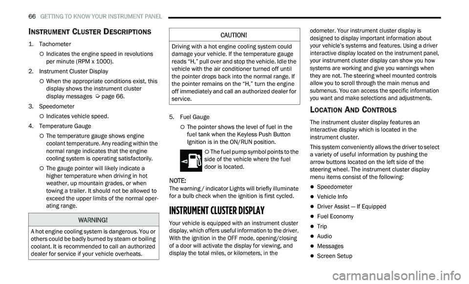
INSTRUMENT CLUSTER DESCRIPTIONS
1. Tachometer
Indicates the engine speed in revolutions
per minute (RPM x 1000).
2. Instrument Cluster Display
When the appropriate conditions exist, this
display shows the instrument cluster
display messages
Ú page 66.
3. S peedometer
Indicates vehicle speed.
4. T emperature Gauge
The temperature gauge shows engine
coolant temperature. Any reading within the
normal range indicates that the engine
cooling system is operating satisfactorily.
The gauge pointer will likely indicate a
higher temperature when driving in hot
weather, up mountain grades, or when
towing a trailer. It should not be allowed to
exceed the upper limits of the normal oper
-
ating range. 5. Fuel Gauge
The pointer shows the level of fuel in the
fuel tank when the Keyless Push Button
Ignition is in the ON/RUN position.
The fuel pump symbol points to the
side of the vehicle where the fuel
d oor
is located.
NOTE:
The warning / indicator Lights will briefly illuminate
f or
a bulb check when the ignition is first cycled.
INSTRUMENT CLUSTER DISPLAY
Your vehicle is equipped with an instrument cluster
display, which offers useful information to the driver.
With the ignition in the OFF mode, opening/closing
of a door will activate the display for viewing, and
display the total miles, or kilometers, in the odometer. Your instrument cluster display is
designed to display important information about
your vehicle’s systems and features. Using a driver
interactive display located on the instrument panel,
your instrument cluster display can show you how
systems are working and give you warnings when
they are not. The steering wheel mounted controls
allow you to scroll through the main menus and
submenus. You can access the specific information
you want and make selections and adjustments.
LOCATION AND CONTROLS
The instrument cluster display features an
interactive display which is located in the
instrument cluster.
This system conveniently allows the driver to select
a
variety of useful information by pushing the
arrow buttons located on the left side of the
steering wheel. The instrument cluster display
menu items consist of the following:
Speedometer
Vehicle Info
Driver Assist — If Equipped
Fuel Economy
Trip
Audio
Messages
Screen Setup
WARNING!
A hot engine cooling system is dangerous. You or
others could be badly burned by steam or boiling
coolant. It is recommended to call an authorized
dealer for service if your vehicle overheats.
CAUTION!
Driving with a hot engine cooling system could
damage your vehicle. If the temperature gauge
reads “H,” pull over and stop the vehicle. Idle the
vehicle with the air conditioner turned off until
the pointer drops back into the normal range. If
the pointer remains on the “H,” turn the engine
off immediately and call an authorized dealer for
service.
Page 70 of 268

68 GETTING TO KNOW YOUR INSTRUMENT PANEL
2. Push and release the down arrow button to
scroll downward through the main menu to
“ V
ehicle Info.”
3. P ush and release the right
arrow button to
access the ”Oil Life” screen.
4. P ush and hold the O
K button to reset oil life. If
conditions are met, the gauge and numeric
display will update to show 100%. If conditions
are not met a pop-up message of "To reset oil
life engine must be off with ignition in run" will
be displayed (for five seconds), and the user
will remain at the Oil Life screen.
5. P ush and release the u
p or down arrow
button to exit the submenu screen.
NOTE:
If the indicator message illuminates when you start
t h
e vehicle, the oil change indicator system did not
reset. If necessary, repeat this procedure.
Secondary Method Of Resetting Engine Oil Life
1. W ithout pressing the brake pedal, push the
E
NGINE START/STOP button and place the
ignition to the ON/RUN position (do not start
the engine).
2. Fully press the accelerator pedal, slowly, three t
imes within ten seconds.
3. Without pushing the brake pedal, push the E
NGINE START/STOP button once to return the
ignition to the OFF position.
NOTE:
If the indicator message illuminates when you start
t h
e vehicle, the oil change indicator system did not
reset. If necessary, repeat this procedure.
INSTRUMENT CLUSTER DISPLAY
S
ELECTABLE MENU ITEMS
Push and release the up or down arrow
button until the desired Selectable Menu item is
d i
splayed in the instrument cluster display.
Follow the Menu or submenu prompts as desired.
Speedometer
Push and release the OK button to toggle between
mph and km/h.
Vehicle Info
The Vehicle Info consists of the following submenu
(pushing the left or right arrow button will
allow you to scroll through the submenu):
Tire Pressure Monitor
Coolant Temperature
Transmission Temperature
Oil Temperature
Oil Pressure
Oil Life
AWD Status — If Equipped
Battery Voltage
Driver Assist — If Equipped
The Driver Assist menu provides the status and a
visual about the Adaptive Cruise Control and
LaneSense features. When they are both off the
screen, the display will read "Adaptive Cruise
Control (ACC) and LaneSense Off."
Adaptive Cruise Control (ACC) Feature —
If Equipped
The instrument cluster display displays the current
A C
C system settings Ú page 94. The information
displayed depends on ACC system status.
Push the ACC ON/OFF button (located on the
s t
eering wheel) until one of the following displays
in the instrument cluster display:
Adaptive Cruise Control Off
When ACC is deactivated, the display will read
“ A
daptive Cruise Control Off.”
Adaptive Cruise Control Ready
When ACC is activated but the vehicle speed
s e
tting has not been selected, the display will read
“Adaptive Cruise Control Ready.”
Push the SET + or the SET- button (located on the
s t
eering wheel) and the following will display in the
instrument cluster display:
ACC Set
When ACC is set, the set speed will display in the
i n
strument cluster.
Page 76 of 268
74 GETTING TO KNOW YOUR INSTRUMENT PANEL
Trunk Open Warning Light
This indicator will illuminate when the
trunk is open and not fully closed.
NOTE:
If the vehicle is moving, there will also be a single
c h
ime.
Oil Pressure Warning Light
This warning light will illuminate to
indicate low engine oil pressure. If the
li
ght turns on while driving, stop the
vehicle, shut off the engine as soon as
possible, and contact an authorized dealer. A
chime will sound when this light turns on.
Do not operate the vehicle until the cause is
c or
rected. This light does not indicate how much oil
is in the engine. The engine oil level must be
checked under the hood.
Oil Temperature Warning Light
This warning light will illuminate to
indicate the engine oil temperature is
h i
gh. If the light turns on while driving,
stop the vehicle and shut off the engine
as soon as possible. Wait for oil temperature to
return to normal levels.
Transmission Temperature Warning Light
— If Equipped
This warning light will illuminate to warn
of a high transmission fluid temperature.
T h
is may occur with strenuous usage
such as trailer towing. If this light turns
on, stop the vehicle and run the engine at idle or
slightly faster, with the transmission in PARK or
NEUTRAL, until the light turns off. Once the light
turns off, you may continue to drive normally.
Vehicle Security Warning Light —
If Equipped
This light will flash at a fast rate for
approximately 15 seconds when the
V e
hicle Security system is arming, and
then will flash slowly until the vehicle is
disarmed.
YELLOW WARNING LIGHTS
Service Adaptive Cruise Control Warning
Light — If Equipped
This light will turn on when a ACC is not
operating and needs service Ú page 94.
Anti-Lock Brake System (ABS) Warning
Light
This warning light monitors the ABS. The
light will turn on when the ignition is
p
l
aced in the ON/RUN or ACC/ON/RUN
position and may stay on for as long as
four seconds.
If the ABS light remains on or turns on while
dr
iving, then the Anti-Lock portion of the brake
system is not functioning and service is required as
soon as possible. However, the conventional brake
system will continue to operate normally,
assuming the Brake Warning Light is not also on.
WARNING!
If you continue operating the vehicle when the
Transmission Temperature Warning Light is
illuminated you could cause the fluid to boil over,
come in contact with hot engine or exhaust
components and cause a fire.
CAUTION!
Continuous driving with the Transmission
Temperature Warning Light illuminated will
eventually cause severe transmission damage
or transmission failure.
Page 197 of 268
195
SERVICING AND MAINTENANCE
SCHEDULED SERVICING
This vehicle is equipped with an automatic oil
change indicator system. The oil change indicator
system will remind you that it is time to take your
vehicle in for scheduled maintenance.
Based on engine operation conditions, the oil
ch
ange indicator message will illuminate. This
means that service is required for the vehicle.
Operating conditions such as frequent short-trips,
trailer tow, and extremely hot or cold ambient
temperatures will influence when the “Change Oil”
or “Oil Change Required” message is displayed.
Have your vehicle serviced as soon as possible,
within the next 500 miles (805 km). The “Oil Change Required” message will be
di
splayed in the instrument cluster and a single
chime will sound, indicating that an oil change is
necessary.
An authorized dealer will reset the oil change
in
dicator message after completing the scheduled
oil change.
NOTE:
Under no circumstances should oil change
i n
tervals exceed 10,000 miles (16,000 km),
1 2
months or 350 hours of engine run time,
w h
ichever comes first. The 350 hours of engine
run or idle time is generally only a concern for fleet
customers. Once A Month Or Before A Long Trip:
Check engine oil level.
Check windshield washer fluid level.
Check tire pressure and look for unusual wear
or damage. Rotate tires at the first sign of irreg
-
ular wear, even if it occurs before your next
s c
heduled service.
Check the fluid levels of the coolant reservoir,
brake master cylinder, and power steering (if
equipped) and fill as needed.
Check function of all interior and exterior lights.
8
Page 203 of 268
SERVICING AND MAINTENANCE 201
(Continued)
CHECKING OIL LEVEL
To ensure proper engine lubrication, the engine oil
must be maintained at the correct level. Check the
oil level at regular intervals, such as every month.
The best time to check the engine oil level is about
five minutes after a fully warmed up engine is shut
off.
Checking the oil while the vehicle is on level ground
w i
ll improve the accuracy of the oil level readings.
There are four possible dipstick types:
Crosshatched zone.
Crosshatched zone marked SAFE.
Crosshatched zone marked with MIN at the low
end of the range and MAX at the high end of the
range.
Crosshatched zone marked with dimples at the
MIN and the MAX ends of the range.
NOTE:
Always maintain the oil level within the crosshatch
m a
rkings on the dipstick.
Adding 1 quart (1.0 liters) of oil when the reading
is
at the low end of the dipstick range will raise the
oil level to the high end of the range marking.
ADDING WASHER FLUID
The windshield washer fluid reservoir is located in
the front of the engine compartment. Be sure to
check the fluid level at regular intervals. Fill the
reservoir with windshield washer solvent (not
radiator antifreeze) and operate the system for a
few seconds to flush out the residual water.
When refilling the washer fluid reservoir, apply
s om
e washer fluid to a cloth or towel and wipe the
wiper blades clean. This will help blade
performance.
To prevent freeze-up of your windshield washer
sy
stem in cold weather, select a solution or mixture
that meets or exceeds the temperature range of
your climate. This rating information can be found
on most washer fluid containers.
The fluid reservoir will hold nearly 1 gallon (4 liters)
of
washer fluid when the message “Low Washer
Fluid” appears in the instrument cluster.
MAINTENANCE-FREE BATTERY
Your vehicle is equipped with a maintenance-free
battery. You will never have to add water, nor is
periodic maintenance required.
NOTE:
The battery is stored under an access cover in the
t r
unk. Remote battery terminals are located in the
engine compartment for jump starting
Ú page 186.
CAUTION!
Overfilling or underfilling the crankcase will
cause aeration or loss of oil pressure. This could
damage your engine.
WARNING!
Commercially available windshield washer
solvents are flammable. They could ignite and
burn you. Care must be exercised when filling or
working around the washer solution.
WARNING!
Battery fluid is a corrosive acid solution and
can burn or even blind you. Do not allow
battery fluid to contact your eyes, skin, or
clothing. Do not lean over a battery when
attaching clamps. If acid splashes in eyes or
on skin, flush the area immediately with large
amounts of water
Ú page 186.
8
Page 214 of 268
212 SERVICING AND MAINTENANCE
(Continued)
BRAKE SYSTEM
In order to ensure brake system performance, all
brake system components should be inspected
periodically
Ú page 195.
Fluid Level Check — Brake Master Cylinder
Check the fluid level in the master cylinder
immediately if the brake system warning light
indicates system failure.
Check the fluid level in the master cylinder when
pe
rforming underhood services.
Clean the top of the master cylinder area before
re
moving the cap. Add fluid to bring the level up to
the top of the “FULL” mark on the side of the
master cylinder reservoir.
Overfilling of fluid is not recommended because it
ma
y cause leaking in the system.
Add enough fluid to bring the level up to the
re
quirements described on the brake fluid reservoir. With disc brakes, fluid level can be
expected to fall as the brake pads wear. However,
low fluid level may be caused by a leak and a
checkup may be needed.
Use only brake fluid that has been recommended
b
y
the manufacturer, and has been kept in a tightly
closed container to avoid contamination from
foreign matter or moisture
Ú page 250.
AUTOMATIC TRANSMISSION
Special Additives
The manufacturer strongly recommends against
using any special additives in the transmission.
Automatic Transmission Fluid (ATF) is an
engineered product and its performance may be
impaired by supplemental additives. Therefore, do
not add any fluid additives to the transmission.
Avoid using transmission sealers as they may
adversely affect seals.
WARNING!
Riding the brakes can lead to brake failure and
possibly a collision. Driving with your foot resting
or riding on the brake pedal can result in
abnormally high brake temperatures, excessive
lining wear, and possible brake damage. You
would not have your full braking capacity in an
emergency.
WARNING!
Use only manufacturer's recommended brake
fluid Ú page 250. Using the wrong type of
brake fluid can severely damage your brake
s y
stem and/or impair its performance. The
proper type of brake fluid for your vehicle is
also identified on the original factory installed
hydraulic master cylinder reservoir.
To avoid contamination from foreign matter or
moisture, use only new brake fluid or fluid that
has been in a tightly closed container. Keep
the master cylinder reservoir cap secured at
all times. Brake fluid in a open container
absorbs moisture from the air resulting in a
lower boiling point. This may cause it to boil
unexpectedly during hard or prolonged
braking, resulting in sudden brake failure. This
could result in a collision.
Overfilling the brake fluid reservoir can result
in spilling brake fluid on hot engine parts,
causing the brake fluid to catch fire. Brake
fluid can also damage painted and vinyl
surfaces, care should be taken to avoid its
contact with these surfaces.
Do not allow petroleum based fluid to contam -
inate the brake fluid. Brake seal components
c ou
ld be damaged, causing partial or
complete brake failure. This could result in a
collision.
WARNING!