2021 CHRYSLER 300 headlamp
[x] Cancel search: headlampPage 43 of 268
GETTING TO KNOW YOUR VEHICLE 41
DAYTIME RUNNING LIGHTS (DRLS)
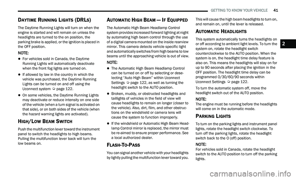
The Daytime Running Lights will turn on when the
engine is started and will remain on unless the
headlights are turned to the on position, the
parking brake is applied, or the ignition is placed in
the OFF position.
NOTE:
For vehicles sold in Canada, the Daytime
Running Lights will automatically deactivate
when the front fog lights are turned on.
If allowed by law in the country in which the
vehicle was purchased, the Daytime Running
Lights can be turned on and off using the
Uconnect system
Ú page 122.
On some vehicles, the Daytime Running Lights
may deactivate or reduce intensity on one side
of the vehicle (when a turn signal is activated on
that side), or on both sides of the vehicle (when
the hazard warning lights are activated).
HIGH/LOW BEAM SWITCH
Push the multifunction lever toward the instrument
panel to switch the headlights to high beams.
Pulling the multifunction lever back will turn the
low beams on.
AUTOMATIC HIGH BEAM — IF EQUIPPED
The Automatic High Beam Headlamp Control
system provides increased forward lighting at night
by automating high beam control through the use
of a digital camera mounted on the inside rearview
mirror. This camera detects vehicle specific light
and automatically switches from high beams to low
beams until the approaching vehicle is out of view.
NOTE:
The Automatic High Beam Headlamp Control
can be turned on or off by selecting or dese
-
lecting “Auto High Beam” within Uconnect
Se
ttings Ú page 122, as well as turning the
headlight switch to the AUTO position.
Broken, muddy, or obstructed headlights and
taillights of vehicles in the field of view will
cause headlights to remain on longer (closer to
the vehicle). Also, dirt, film, and other obstruc -
tions on the windshield or camera lens will
c a
use the system to function improperly.
If the windshield or Automatic High Beam Head -
lamp Control mirror is replaced, the mirror must
b e
re-aimed to ensure proper performance. See
a local authorized dealer.
FLASH-TO-PASS
You can signal another vehicle with your headlights
by lightly pulling the multifunction lever toward you. This will cause the high beam headlights to turn on,
and remain on, until the lever is released.
AUTOMATIC HEADLIGHTS
This system automatically turns the headlights on
or off according to ambient light levels. To turn the
system on, rotate the headlight switch
counterclockwise to the AUTO position. When the
system is on, the headlight time delay feature is
also on. This means the headlights will stay on for
up to 90 seconds after placing the ignition in the
OFF position. The headlight time delay can be
programmed 0/30/60/90 seconds within
Uconnect Settings
Ú page 122.
To turn the automatic system off, move the
h e
adlight switch out of the AUTO position.
NOTE:
The engine must be running before the headlights
w i
ll come on in the automatic mode.
PARKING LIGHTS
To turn on the parking lights and instrument panel
lights, rotate the headlight switch clockwise. To
turn off the parking lights, rotate the headlight
switch back to the O (off) position.
NOTE:
For vehicles sold in Canada, rotate the headlight
s w
itch to the AUTO position to turn off the parking
lights.
2
Page 166 of 268
164 SAFETY
If A Deployment Occurs
The front air bags are designed to deflate
immediately after deployment.
NOTE:
Front and/or side air bags will not deploy in all colli -
sions. This does not mean something is wrong with
t h
e air bag system.
If you do have a collision which deploys the air
ba
gs, any or all of the following may occur:
The air bag material may sometimes cause
abrasions and/or skin reddening to the occu -
pants as the air bags deploy and unfold. The
ab
rasions are similar to friction rope burns or
those you might get sliding along a carpet or
gymnasium floor. They are not caused by
contact with chemicals. They are not permanent
and normally heal quickly. However, if you
haven’t healed significantly within a few days, or
if you have any blistering, see your doctor imme -
diately.
As the air bags deflate, you may see some
smoke-like particles. The particles are a normal
by-product of the process that generates the
non-toxic gas used for air bag inflation. These
airborne particles may irritate the skin, eyes,
nose, or throat. If you have skin or eye irritation,
rinse the area with cool water. For nose or throat
irritation, move to fresh air. If the irritation
continues, see your doctor. If these particles settle on your clothing, follow the garment
manufacturer’s instructions for cleaning.
Do not drive your vehicle after the air bags have
d e
ployed. If you are involved in another collision,
the air bags will not be in place to protect you.
NOTE:
Air bag covers may not be obvious in the interior
trim, but they will open during air bag deploy -
ment.
After any collision, the vehicle should be taken
to an authorized dealer immediately.
Enhanced Accident Response System
In the event of an impact, if the communication
network remains intact, and the power remains
intact, depending on the nature of the event, the
Occupant Restraint Controller (ORC) will determine
whether to have the Enhanced Accident Response
System perform the following functions:
Cut off fuel to the engine (if equipped).
Cut off battery power to the electric motor (if
equipped).
Flash hazard lights as long as the battery has
power.
Turn on the interior lights, which remain on as
long as the battery has power or for 15 minutes
f r
om the intervention of the Enhanced Accident
Response System.
Unlock the power door locks.
Your vehicle may also be designed to perform any
of
these other functions in response to the
Enhanced Accident Response System:
Turn off the Fuel Filter Heater, Turn off the HVAC
Blower Motor, Close the HVAC Circulation Door
Cut off battery power to the:
Engine
Electric Motor (if equipped)
Electric power steering
Brake booster
Electric park brake
Automatic transmission gear selector
Horn
Front wiper
Headlamp washer pump
WARNING!
Deployed air bags and seat belt pretensioners
cannot protect you in another collision. Have the
air bags, seat belt pretensioners, and the seat
belt retractor assemblies replaced by an
authorized dealer immediately. Also, have the
Occupant Restraint Controller System serviced
as well.
Page 217 of 268
SERVICING AND MAINTENANCE 215
CAUTION!
When installing the power distribution center cover, it is important to ensure the cover is properly positioned and fully latched. Failure to do so may allow
water to get into the power distribution center and possibly result in an electrical system failure.
When replacing a blown fuse, it is important to use only a fuse having the correct amperage rating. The use of a fuse with a rating other than indicated may
result in a dangerous electrical system overload. If a properly rated fuse continues to blow, it indicates a problem in the circuit that must be corrected.
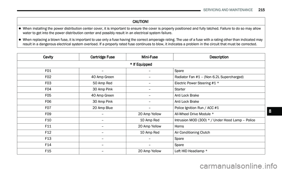
Cavity Cartridge Fuse Mini-Fuse Description
* If Equipped
F01 ––Spare
F02 40 Amp Green –Radiator Fan #1 – (Non 6.2L Supercharged)
F03 50 Amp Red –Electric Power Steering #1 *
F04 30 Amp Pink –Starter
F05 40 Amp Green –Anti Lock Brake
F06 30 Amp Pink –Anti Lock Brake
F07 20 Amp Blue –Police Ignition Run / ACC #1
F09 –20 Amp YellowAll-Wheel Drive Module *
F10 –10 Amp RedIntrusion MOD (300) * / Under Hood Lamp – Police
F11 –20 Amp YellowHorns
F12 –10 Amp RedAir Conditioning Clutch
F13 ––Spare
F14 ––Spare
F15 –20 Amp YellowLeft HID Headlamp *
8
Page 218 of 268
216 SERVICING AND MAINTENANCE
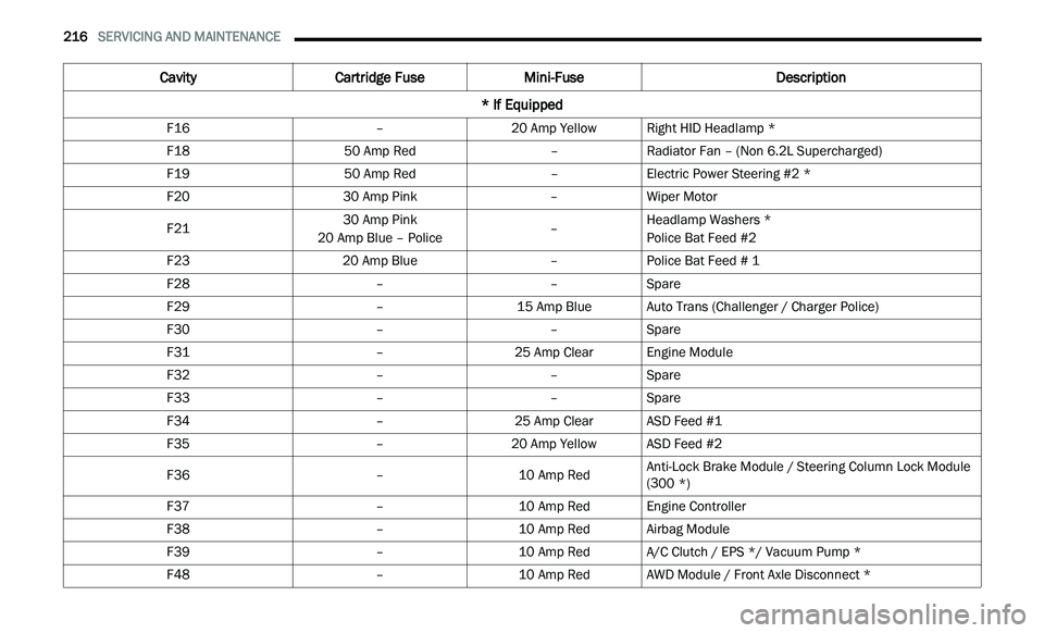
F16 –20 Amp YellowRight HID Headlamp *
F18 50 Amp Red –Radiator Fan – (Non 6.2L Supercharged)
F19 50 Amp Red –Electric Power Steering #2 *
F20 30 Amp Pink –Wiper Motor
F21 30 Amp Pink
20 Amp Blue – Police –Headlamp Washers *
Police Bat Feed #2
F23 20 Amp Blue –Police Bat Feed # 1
F28 ––Spare
F29 –15 Amp BlueAuto Trans (Challenger / Charger Police)
F30 ––Spare
F31 –25 Amp ClearEngine Module
F32 ––Spare
F33 ––Spare
F34 –25 Amp ClearASD Feed #1
F35 –20 Amp YellowASD Feed #2
F36 –10 Amp RedAnti-Lock Brake Module / Steering Column Lock Module
(
3
00 *)
F37 –10 Amp RedEngine Controller
F38 –10 Amp RedAirbag Module
F39 –10 Amp RedA/C Clutch / EPS */ Vacuum Pump *
F48 –10 Amp RedAWD Module / Front Axle Disconnect *
Cavity Cartridge Fuse Mini-Fuse Description
* If Equipped
Page 224 of 268
222 SERVICING AND MAINTENANCE
Replacing Exterior Bulbs
HIGH INTENSITY DISCHARGE (HID) HEAD -
LAMPS — IF EQUIPPED
The headlamps are a type of high voltage
discharge tube. High voltage can remain in the
circuit even with the headlamp switch off and the
ignition turned to the OFF position. Because of this,
you should not attempt to service a headlamp bulb yourself. If a headlamp bulb fails, take your vehicle
to an authorized dealer for service.
NOTE:
On vehicles equipped with HID headlamps, when
t h
e headlamps are turned on, there is a blue hue
to the lights. This diminishes and becomes more
white after approximately 10 seconds, as the
system charges.
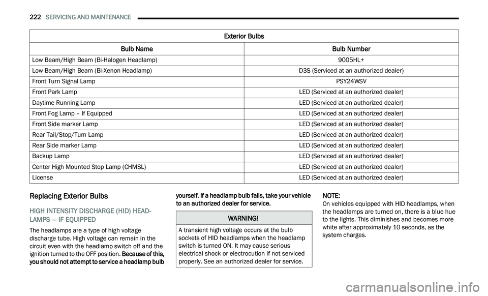
Exterior Bulbs
Bulb Name Bulb Number
Low Beam/High Beam (Bi-Halogen Headlamp) 9005HL+
Low Beam/High Beam (Bi-Xenon Headlamp) D3S (Serviced at an authorized dealer)
Front Turn Signal Lamp PSY24WSV
Front Park Lamp LED (Serviced at an authorized dealer)
Daytime Running Lamp LED (Serviced at an authorized dealer)
Front Fog Lamp – If Equipped LED (Serviced at an authorized dealer)
Front Side marker Lamp LED (Serviced at an authorized dealer)
Rear Tail/Stop/Turn Lamp LED (Serviced at an authorized dealer)
Rear Side marker Lamp LED (Serviced at an authorized dealer)
Backup Lamp LED (Serviced at an authorized dealer)
Center High Mounted Stop Lamp (CHMSL) LED (Serviced at an authorized dealer)
License LED (Serviced at an authorized dealer)
WARNING!
A transient high voltage occurs at the bulb
sockets of HID headlamps when the headlamp
switch is turned ON. It may cause serious
electrical shock or electrocution if not serviced
properly. See an authorized dealer for service.
Page 225 of 268
SERVICING AND MAINTENANCE 223
BI-HALOGEN LOW BEAM AND HIGH BEAM
HEADLAMP — IF EQUIPPED
See steps below to replace:
1. O pen the hood.
NOTE:
Removal of the air cleaner filter housing may be
n e
cessary prior to replacing bulbs in the headlamp
assembly on the driver side of the vehicle.
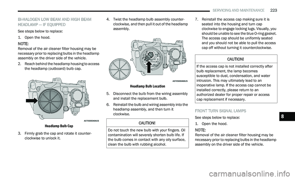
2. R each behind the headlamp housing to access
t
he headlamp (outboard) bulb cap.
Headlamp Bulb Cap
3. F irmly grab the cap and rotate it counter -
c
lockwise to unlock it. 4. Twist the headlamp bulb assembly counter
-
c
lockwise, and then pull it out of the headlamp
a s
sembly.
Headlamp Bulb Location
5. D isconnect the bulb from the wiring assembly
a
nd install the replacement bulb.
6. Reinstall the bulb and wiring assembly into the h
eadlamp assembly, and then turn it
clockwise. 7. Reinstall the access cap making sure it is
s
eated into the housing and turn cap
clockwise to engage locking lugs. Visually, you
should be unable to see the blue O-ring gasket.
The access cap should be uniformly seated
and you should not be able to pull the access
cap off without turning it counterclockwise.
FRONT TURN SIGNAL LAMPS
See steps below to replace:
1. O pen the hood.
NOTE:
Removal of the air cleaner filter housing may be
n e
cessary prior to replacing bulbs in the headlamp
assembly on the driver side of the vehicle.
CAUTION!
Do not touch the new bulb with your fingers. Oil
contamination will severely shorten bulb life. If
the bulb comes in contact with any oily surface,
clean the bulb with rubbing alcohol.
CAUTION!
If the access cap is not installed correctly after
bulb replacement, the lamp becomes
susceptible to dust, condensation, and water
intrusion. This may ultimately lead to an
inoperative lamp. If the access cap cannot be
installed correctly, please return to an
authorized dealer for proper repair or access
cap replacement if necessary.
8
Page 226 of 268
224 SERVICING AND MAINTENANCE
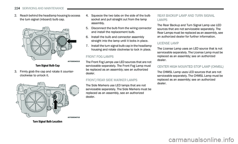
2. Reach behind the headlamp housing to access
the turn signal (inboard) bulb cap.
Turn Signal Bulb Cap
3. F irmly grab the cap and rotate it counter -
c
lockwise to unlock it.
Turn Signal Bulb Location
4. S
queeze the two tabs on the side of the bulb
s
ocket and pull straight out from the lamp
assembly.
5. D isconnect the bulb from the wiring connector
a
nd install the replacement bulb.
6. Install the bulb and connector assembly s
traight into the lamp until it locks in place.
7. Install the turn signal bulb cap in the headlamp h
ousing and rotate clockwise to lock in place.
FRONT FOG LAMPS
The Front Fog Lamps use LED sources that are not
serviceable separately. The Front Fog Lamp must
be replaced as an assembly; see an authorized
dealer.
FRONT/REAR SIDE MARKER LAMPS
The Side Markers use LED lamps that are not
serviceable separately. The Side Markers must be
replaced as an assembly, see an authorized
dealer.
REAR BACKUP LAMP AND TURN SIGNAL
LAMPS
The Rear Backup and Turn Signal Lamp use LED
sources that are not serviceable separately. The
Rear Lamps must be replaced as an assembly, see
an authorized dealer for further information.
LICENSE LAMP
The License Lamp uses an LED source that is not
serviceable separately. The License Lamp must be
replaced as an assembly; see an authorized
dealer.
CENTER HIGH MOUNTED STOP LAMP (CHMSL)
The CHMSL Lamp uses LED sources that are not
serviceable separately. The CHMSL Lamp must be
replaced as an assembly; see an authorized
dealer.