2021 ALFA ROMEO STELVIO maintenance
[x] Cancel search: maintenancePage 4 of 280
2
READ THIS CAREFULLY
Refueling
Gas engines: Do not use fuel containing methanol or ethanol E85. Using these mixtures may cause misfiring and driving issues, as well
as damage vital components of the supply system.
Diesel engines: Do not use other products or mixtures as they may cause damage to the engine beyond repair and consequently invali -
date the warranty. For further details on the use of the correct fuel, see
Ú
page 255.
Starting The Engine
Make sure that the electric park brake is engaged and that the transmission is in PARK (P) or NEUTRAL (N). Next, press the brake pedal,
and then push the engine START/STOP button.
Parking On Flammable Material
The catalytic converter develops high temperatures during operation. Do not park the vehicle on potential fire hazards such as: grass, dry
leaves, pine needles or other flammable material.
Respecting The Environment
The vehicle is fitted with a system that carries out a continuous diagnosis of the emission-related components in order to help protect the
environment (if equipped).
Electrical Accessories
If you decide to add electrical accessories after purchasing the vehicle, with the risk of gradually draining the battery, contact an autho -
rized dealer. They can calculate the overall electrical requirement and check that the vehicle's electric system can support the required
load.
Scheduled Servicing
Correctly performed maintenance procedures are essential for ensuring that your vehicle continuously maintains its quality in perfor -
mance and safety features, environmental friendliness, and low running costs.
21_GU_OM_EN_USC_t.book Page 2
Page 9 of 280

GETTING TO KNOW YOUR VEHICLE
GETTING TO KNOW YOUR INSTRUMENT PANEL STARTING AND OPERATING SAFETY
IN CASE OF EMERGENCY
SERVICING AND MAINTENANCE TECHNICAL SPECIFICATIONS CUSTOMER ASSISTANCE INDEX
21_GU_OM_EN_USC_t.book Page 7
Page 11 of 280
9
Automatic High Beam Headlights —
If Equipped ............................................. 43 Parking Lights ....................................... 44
Headlight Off Delay ................................ 44
Rear Fog Lights ...................................... 44
Adaptive Headlight System (AFS) —
If Equipped ............................................. 44 Turn Signals ........................................ 44
Lane Change Assist ............................... 44
INTERIOR LIGHTS .....................................44
Front Map Reading Lights ..................... 45
Interior Ambient Lighting ...................... 45
Rear Overhead Light ............................. 46
Instrument Panel Dimmer Control ....... 46
WINDSHIELD WIPERS AND WASHERS....46
Windshield Wiper Operation ............... 46
Rain Sensing Wipers.............................. 47
Rear Window Wiper/Washer................. 48
Headlamp Washers — If Equipped ....... 48
CLIMATE CONTROLS ................................48
Automatic Dual-Zone Climate Control
System ................................................. 49
INTERIOR STORAGE AND EQUIPMENT....55
Glove Compartment............................... 55
Center Console ...................................... 56
Rear Armrest .......................................... 56
Power Outlets ...................................... 56
Cigar Lighter And Ash Tray —
If Equipped ............................................. 57 Wireless Charging Pad — If Equipped... 57
POWER WINDOWS ................................... 58
Power Window Controls ........................ 58
Auto-Up Feature With Anti-Pinch
Protection............................................... 59 Power Window System Initialization .... 59
Wind Buffeting ...................................... 59
POWER SUNROOF — IF EQUIPPED.......... 59
Power Sunroof ....................................... 59
Opening And Closing The Sunroof ........ 60
Venting Sunroof ..................................... 60
Sunshade Operation ............................. 60
Pinch Protect Feature ........................... 60
Re-Initialization Procedure.................... 60
Sunroof Maintenance ........................... 61
HOOD ........................................................ 61
Opening The Hood ................................. 61
Closing The Hood................................... 62
POWER LIFTGATE..................................... 62
Opening .................................................. 62
Closing.................................................... 63
Liftgate Initialization .............................. 64
Cargo Area Features ............................. 64
GETTING TO KNOW YOUR INSTRUMENT
PANEL
INSTRUMENT PANEL FEATURES............. 67
Instrument Cluster ............................... 67
Instrument Cluster Descriptions .......... 68
INSTRUMENT CLUSTER DISPLAY ............69
Instrument Cluster Display
Description .............................................69 Reconfigurable Instrument Cluster
Display ....................................................69 Reconfigurable Display Items ............... 69
Customer Programmable Settings........ 72
WARNING LIGHTS AND MESSAGES
ON THE INSTRUMENT PANEL ..................74
Red Warning Lights ................................74
Amber Warning Lights............................ 75
Green Indicator Lights ...........................78
Blue Indicator Lights ..............................78
Red Symbols...........................................78
Amber Symbols ......................................80
Green Symbols .......................................84
Blue Symbols .......................................... 84
ONBOARD DIAGNOSTIC SYSTEM ............84
Onboard Diagnostic System (OBD II)
Cybersecurity .......................................... 84
EMISSIONS INSPECTION AND
MAINTENANCE PROGRAM .......................85
21_GU_OM_EN_USC_t.book Page 9
Page 14 of 280

12
JUMP STARTING .................................... 201
Remote Battery Connection Posts......202
Jump Starting Procedure.....................203
Bump Starting ..................................204
ENGINE OVERHEATING ......................... 204 MANUAL PARK RELEASE ...................... 205TOWING A DISABLED VEHICLE ............. 205
Four-Wheel Drive (AWD) Models .........206
TOW EYES .............................................. 206
ENHANCED ACCIDENT RESPONSE
SYSTEM (EARS) ..................................... 207EVENT DATA RECORDER (EDR) ............ 207
SERVICING AND MAINTENANCE
SCHEDULED SERVICING ....................... 208
Periodic Checks ...................................208
Heavy Usage Of The Vehicle ...............208
Maintenance Plan (2.0L Engine) ........209
Maintenance Plan (2.9L Engine) ........212
ENGINE COMPARTMENT....................... 214
Checking Levels — 2.0L Engine .......... 214
Checking Levels — 2.9L Engine .......... 215
Engine Oil ............................................. 215
Engine Coolant Fluid............................216
Washer Fluid For Windshield/
Headlights ............................................ 217 Brake Fluid ...........................................217
Automatic Transmission Activation
System Oil ............................................ 217 Useful Advice For Extending The Life Of
Your Battery..........................................217 Battery ..................................................217
Pressure Washing ................................ 218
BATTERY RECHARGING ......................... 218
Important Notes .................................. 218
VEHICLE MAINTENANCE ........................ 219
Engine Oil ............................................. 219
Engine Oil Filter ................................... 220
Engine Air Cleaner Filter ..................... 220
Air Conditioning System
Maintenance........................................ 220 Lubricating Moving Parts Of The
Bodywork ............................................. 220 Windshield Wiper................................. 221
Exhaust System ................................... 222
Cooling System .................................... 223
Braking System.................................... 224
Automatic Transmission ..................... 225
Replacing The Battery ......................... 225
Fuses .................................................... 225
Bulb Replacement ............................... 229
TIRES ...................................................... 233
Tire Safety Information .................... 233
Tires — General Information .............. 239
Spare Tires — If Equipped .................. 244
Wheel And Wheel Trim Care ............ 245
Tire Types ............................................. 246
Tire Chains and Traction Devices ....... 247
Tire Rotation Recommendations........ 247
DEPARTMENT OF TRANSPORTATION
UNIFORM TIRE QUALITY GRADES ......... 248
Treadwear ............................................ 248
Traction Grades ................................... 248
Temperature Grades ........................... 248
STORING THE VEHICLE ......................... 249 BODYWORK ........................................... 249
Protection Against Atmospheric
Agents .................................................. 249 Corrosion Warranty ............................. 250
Preserving The Bodywork .................. 250
INTERIORS ............................................. 251
Seats And Fabric Parts ....................... 251
Leather Seats ...................................... 251
Plastic And Coated Parts .................... 251
Alcantara Parts — If Equipped ............ 251
Genuine Leather Parts........................ 251
Carbon Fiber Parts .............................. 252
TECHNICAL SPECIFICATIONS
VEHICLE IDENTIFICATION
NUMBER (VIN) ....................................... 253
Vehicle Identification Number............ 253
Vehicle Identification Number
(VIN) Plate ............................................ 253
ENGINE .................................................. 254
POWER SUPPLY ..................................... 255 TRANSMISSION ..................................... 255BRAKES.................................................. 255
SUSPENSION ......................................... 256
STEERING .............................................. 256
DIMENSIONS ......................................... 257
Luggage Compartment Volume ......... 259
WEIGHTS ................................................ 259
21_GU_OM_EN_USC_t.book Page 12
Page 57 of 280
55
Humidity Sensor
The Humidity Sensor helps prevent the
windows from fogging up. The AUTO function
(indicator illuminated) must be on for the
Humidity Sensor to function.
When outside temperature is low, the system
may turn the compressor on and turn air recir-
culation off for safer driving.
Stop/Start
The Stop/Start system shuts off the engine
when the vehicle speed is 0 mph (0 km/h), as
a fuel conservation measure.
In order to maintain comfort in the cabin, the
Stop/Start feature will not activate if any of the
following conditions exist:
The Climate Control system is in AUTO mode
(indicator illuminated), and the vehicle has
yet to reach the set temperature
The Climate Control system is in LO
maximum cooling
The Climate Control system is in HI
maximum heating
The Climate Control system is in the
MAX-DEF status
When the Stop/Start system is active, the
engine will restart if the inside temperature
changes significantly, or if the LO setting, or
MAX-DEF setting, is activated. With Stop/Start system on (engine is OFF), air
flow is reduced to keep the compartment
comfort conditions for longer.
Until the temperature drastically changes
within the cabin, the climate control system
will continue to maintain the temperature
while the engine is off. By deactivating the
Stop/Start system with the button (located
by the headlight switch), the climate control
system operates normally according to the
settings.
NOTE:
In harsh climate conditions, limit the use of
the Stop/Start system to prevent the
compressor from continuously switching on
and off. This will cause rapid misting of the
windows and the accumulation of humidity
in the passenger compartment.
When the Stop/Start system is on, the
climate control system will always take air in
from outside, reducing the probability of the
windows fogging up.
System Maintenance
In winter months, the Climate Control system
must be turned on at least once a month for
approximately 10 minutes.
Have the system inspected at an authorized
dealer before the summer.
INTERIOR STORAGE AND
EQUIPMENT
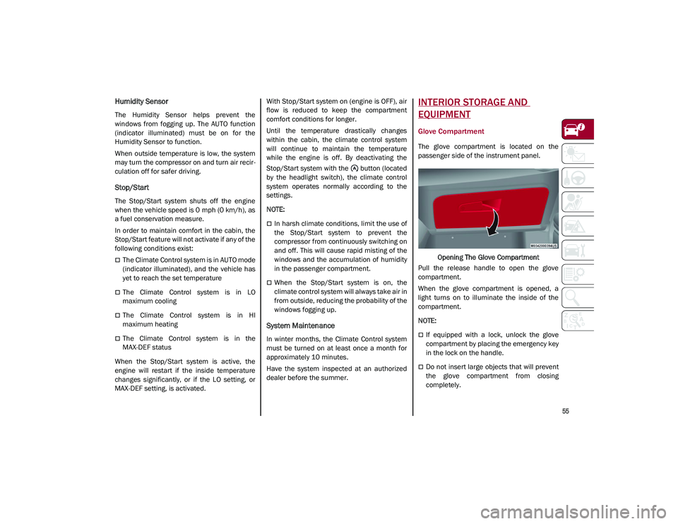
Glove Compartment
The glove compartment is located on the
passenger side of the instrument panel.
Opening The Glove Compartment
Pull the release handle to open the glove
compartment.
When the glove compartment is opened, a
light turns on to illuminate the inside of the
compartment.
NOTE:
If equipped with a lock, unlock the glove
compartment by placing the emergency key
in the lock on the handle.
Do not insert large objects that will prevent
the glove compartment from closing
completely.
21_GU_OM_EN_USC_t.book Page 55
Page 63 of 280
61
Proceed as follows:
1. With the ignition in the ON/RUN position,make sure the sunroof glass is fully closed
(sunshade open).
2. Open the driver’s side door, and place the ignition in the OFF position.
3. Within five seconds, place the ignition in the ACC or ON/RUN position.
4. Within 10 seconds, push and hold the sunroof close switch (forward). After 8 -
10 seconds of holding the switch, the
re-initialization process will begin.
Continue to hold the switch while the
sunroof motor cycles, and the sunshade
will fully close.
5. Once the sunroof glass and the power sunshade have stopped motion, release
the sunroof close switch, then push and
hold it again within five seconds. Continue
to hold the switch while the sunshade fully
opens, the sunroof glass fully opens,
followed by the glass fully closing then the
sunshade fully closing.
6. Release the switch once all of the opera -
tions stop. Re-initialization of the sunroof
motors is now complete.
NOTE:
If the switch is released prior to full completion
of the operations described, the entire
re-initialization procedure must be repeated
from step 1. 7. Confirm express operations for the
sunroof glass and sunshade are functional
for opening and closing operations.
Sunroof Maintenance
Use only a non-abrasive cleaner and a soft
cloth to clean the glass panel. Periodically
check for and clear out any debris that may
have collected in the tracks.
HOOD
Opening The Hood
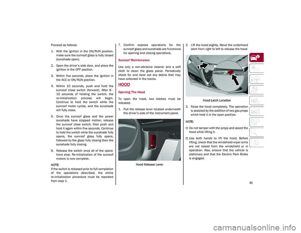
To open the hood, two latches must be
released.
1. Pull the release lever located underneaththe driver’s side of the instrument panel.
Hood Release Lever 2. Lift the hood slightly. Move the underhood
latch from right to left to release the hood.
Hood Latch Location
3. Raise the hood completely. The operation is assisted by the addition of two gas props
which hold it in the open position.
NOTE:
Do not tamper with the props and assist the
hood while lifting it.
Use both hands to lift the hood. Before
lifting, check that the windshield wiper arms
are not raised from the windshield or in
operation. Also, ensure that the vehicle is
stationary and that the Electric Park Brake
is engaged.
21_GU_OM_EN_USC_t.book Page 61
Page 79 of 280
77
also reduces fuel efficiency and tire tread life,
and may affect the vehicle’s handling and
stopping ability.
Please note that the TPMS is not a substitute
for proper tire maintenance, and it is the
driver’s responsibility to maintain correct tire
pressure, even if under inflation has not
reached the level to trigger illumination of the
TPMS low tire pressure telltale.
Your vehicle has also been equipped with a
TPMS malfunction indicator to indicate when
the system is not operating properly. The
TPMS malfunction indicator is combined with
the low tire pressure telltale. When the system
detects a malfunction, the telltale will flash for
approximately one minute and then remain
continuously illuminated. This sequence will
continue upon subsequent vehicle start-ups
as long as the malfunction exists. When the
malfunction indicator is illuminated, the
system may not be able to detect or signal low
tire pressure as intended. TPMS malfunctions
may occur for a variety of reasons, including
the installation of replacement or alternate
tires or wheels on the vehicle that prevent the
TPMS from functioning properly. Always check
the TPMS malfunction telltale after replacing
one or more tires or wheels on your vehicle to
ensure that the replacement or alternate tires
and wheels allow the TPMS to continue to
function properly.
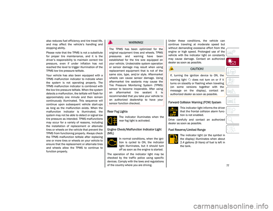
Rear Fog Lights
The indicator illuminates when the
rear fog light is activated.
Engine Check/Malfunction Indicator Light
(MIL)
In normal conditions, when the igni-
tion is cycled to ON, the indicator
light illuminates, but it should turn
off as soon as the engine is started.
The operation of the indicator light may be
checked by the traffic police using specific
devices. Comply with the laws and regulations
of the country where you are driving. Under these conditions, the vehicle can
continue traveling at moderate speed but
without demanding excessive effort from the
engine or high speed. Prolonged use of the
vehicle with the indicator light on constantly
may cause damage. Contact an authorized
dealer as soon as possible.
Forward Collision Warning (FCW) System
This indicator light informs the driver
that the frontal collision alarm func
-
tion is not enabled.
Drive carefully and contact an authorized
dealer as soon as possible.
Fuel Reserve/Limited Range
The indicator light (or the symbol in
the display) illuminates when about
2.4 gallons (9 liters) of fuel is left in
the tank.
WARNING!
The TPMS has been optimized for the
original equipment tires and wheels. TPMS
pressures and warning have been
established for the tire size equipped on
your vehicle. Undesirable system operation
or sensor damage may result when using
replacement equipment that is not of the
same size, type, and/or style. Aftermarket
wheels can cause sensor damage. Using
aftermarket tire sealants may cause the
Tire Pressure Monitoring System (TPMS)
sensor to become inoperable. After using
an aftermarket tire sealant it is
recommended that you take your vehicle to
an authorized dealership to have your
sensor function checked.
CAUTION!
If, turning the ignition device to ON, the
warning light does not turn on or if it
turns on steadily or flashing when traveling
(on some versions together with the
message on the display), contact an
authorized dealer as soon as possible.
21_GU_OM_EN_USC_t.book Page 77
Page 87 of 280

85
EMISSIONS INSPECTION AND
MAINTENANCE PROGRAM
In some localities, it may be a legal require-
ment to pass an inspection of your vehicle's
emissions control system. Failure to pass
could prevent vehicle registration. For states that require an Inspection
and Maintenance (I/M), this check
verifies the Malfunction Indicator
Light (MIL) is functioning and is not
on when the engine is running, and that the
OBD II system is ready for testing.
Normally, the OBD II system will be ready. The
OBD II system may not be ready if your vehicle
was recently serviced, recently had a depleted
battery or a battery replacement. If the OBD II
system should be determined not ready for the
I/M test, your vehicle may fail the test.
Your vehicle has a simple ignition actuated
test, which you can use prior to going to the
test station. To check if your vehicle's OBD II
system is ready, you must do the following:
1. Cycle the ignition switch to the ACC posi -
tion, but do not crank or start the engine.
NOTE:
If you crank or start the engine, you will have to
start this test over.
2. As soon as you cycle the ignition switch to the ACC position, you will see the Malfunc -
tion Indicator Light (MIL) symbol come on
as part of a normal bulb check. 3. Approximately 15 seconds later, one of
two things will happen:
• The MIL will flash for about 10 seconds
and then return to being fully illumi-
nated until you turn OFF the ignition or
start the engine. This means that your
vehicle's OBD II system is not ready and
you should not proceed to the I/M
station.
• The MIL will not flash at all and will
remain fully illuminated until you place the ignition in the off position or start
the engine. This means that your
vehicle's OBD II system is ready and you
can proceed to the I/M station.
If y o
ur OBD II system is not ready, you should
see an authorized dealer or repair facility. If
your vehicle was recently serviced or had a
battery failure or replacement, you may need
to do nothing more than drive your vehicle as
you normally would in order for your OBD II
system to update. A recheck with the above
test routine may then indicate that the system
is now ready .
Regardless of whether your vehicle's OBD II
system is ready or not, if the MIL is illuminated
during normal vehicle operation you should
have your vehicle serviced before going to the
I/M station. The I/M station can fail your
vehicle because the MIL is on with the engine
running.
WARNING!
ONLY an authorized service technician
should connect equipment to the OBD II
connection port in order to read the VIN,
diagnose, or service your vehicle.
If unauthorized equipment is connected to
the OBD II connection port, such as a
driver-behavior tracking device, it may:
• Be possible that vehicle systems,
including safety related systems,
could be impaired or a loss of vehicle
control could occur that may result in an accident involving serious injury or
death.
• Access, or allow others to access,
information stored in your vehicle
systems, including personal informa-
tion.
21_GU_OM_EN_USC_t.book Page 85