2021 ALFA ROMEO STELVIO engine
[x] Cancel search: enginePage 111 of 280
109
To Pause/Deactivate
With the feature enabled (speed not set), push
the on/off button to disable.
With the feature active (speed set), push the
on/off button to pause. The display will show
the icon in white with the speed in brackets. To
deactivate the feature, push the on/off button
a second time.
To Set A Desired Speed
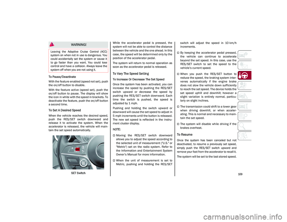
When the vehicle reaches the desired speed,
push the RES/SET switch downward and
release it to activate the system. When the
accelerator is released, the vehicle will main-
tain the set speed automatically.
SET Switch While the accelerator pedal is pressed, the
system will not be able to control the distance
between the vehicle and the one ahead. In this
case, the speed will be determined only by the
position of the accelerator pedal.
The system will return to normal operation as
soon as the accelerator pedal is released.
To Vary The Speed Setting
To Increase Or Decrease The Set Speed
Once the system has been activated, you can
increase the speed by pushing the RES/SET
switch upward or decrease the speed by
pushing the RES/SET switch downward. Each
time the switch is pushed, the speed is
adjusted by 1 mph.
Pushing and holding the switch upward or
downward will cause the set speed to adjust in
5 mph increments until the button is released.
The new set speed is reflected in the instru
-
ment cluster display.
NOTE:
Moving the RES/SET switch downward
allows you to adjust the speed according to
the selected unit of measurement ("U.S." or
"Metric") set on the radio system. Refer to
the Information and Entertainment System
Owner’s Manual for more information.
When the unit of measurement is set to
Metric, pushing and holding the RES/SET switch will adjust the speed in 10 km/h
increments.
By keeping the accelerator pedal pressed,
the vehicle can continue to accelerate
beyond the set speed. In this case, use the
RES/SET switch to set the speed to the
vehicle’s current speed.
When you push the RES/SET button to
reduce the speed, the braking system inter
-
venes automatically if the engine brake
does not slow the vehicle down sufficiently
to reach the set speed. The device holds the
set speed uphill and downhill; however a
slight variation is entirely normal, particu -
larly on slight inclines.
The transmission could shift to a lower gear
when driving downhill, or when acceler -
ating. This is normal and necessary to main -
tain the set speed.
The system will disable while driving if the
brakes overheat.
To Resume
Once the system has been canceled but not
deactivated, to resume a previously set speed,
simply push the RES/SET switch upward and
remove your foot from the accelerator to recall it.
The system will be set to the last stored speed.
WARNING!
Leaving the Adaptive Cruise Control (ACC)
system on when not in use is dangerous. You
could accidentally set the system or cause it
to go faster than you want. You could lose
control and have a collision. Always leave the
system off when you are not using it.
21_GU_OM_EN_USC_t.book Page 109
Page 127 of 280
125
Pushing the button a second time will turn the
system back on, and the indicator light will
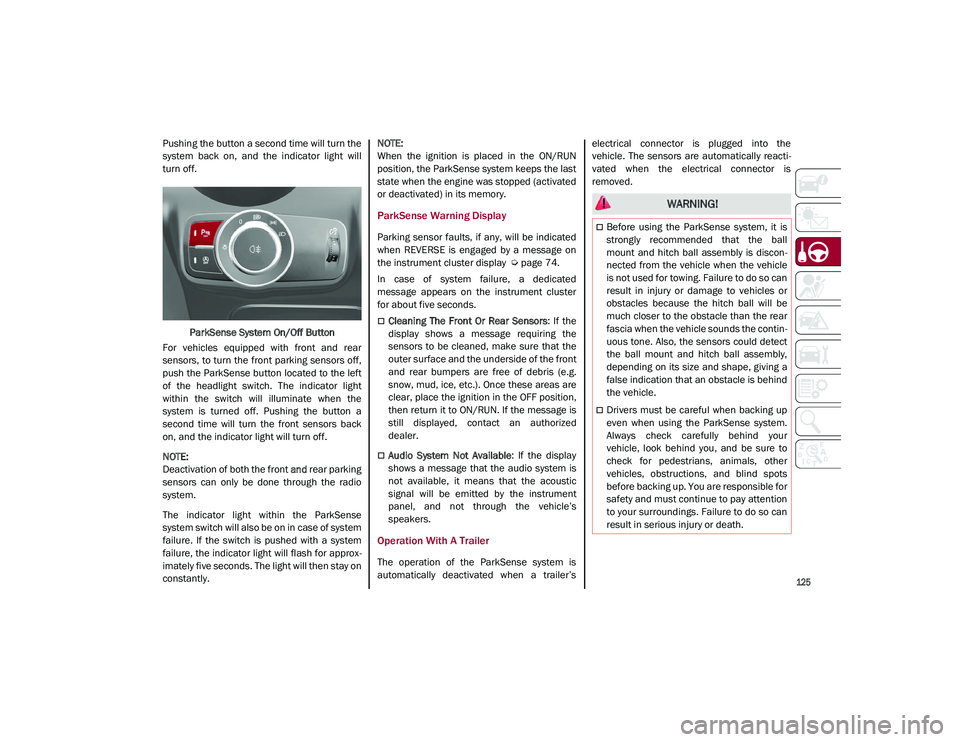
turn off.ParkSense System On/Off Button
For vehicles equipped with front and rear
sensors, to turn the front parking sensors off,
push the ParkSense button located to the left
of the headlight switch. The indicator light
within the switch will illuminate when the
system is turned off. Pushing the button a
second time will turn the front sensors back
on, and the indicator light will turn off.
NOTE:
Deactivation of both the front and rear parking
sensors can only be done through the radio
system.
The indicator light within the ParkSense
system switch will also be on in case of system
failure. If the switch is pushed with a system
failure, the indicator light will flash for approx -
imately five seconds. The light will then stay on
constantly.
NOTE:
When the ignition is placed in the ON/RUN
position, the ParkSense system keeps the last
state when the engine was stopped (activated
or deactivated) in its memory.
ParkSense Warning Display
Parking sensor faults, if any, will be indicated
when REVERSE is engaged by a message on
the instrument cluster display
Ú
page 74.
In case of system failure, a dedicated
message appears on the instrument cluster
for about five seconds.
Cleaning The Front Or Rear Sensors : If the
display shows a message requiring the
sensors to be cleaned, make sure that the
outer surface and the underside of the front
and rear bumpers are free of debris (e.g.
snow, mud, ice, etc.). Once these areas are
clear, place the ignition in the OFF position,
then return it to ON/RUN. If the message is
still displayed, contact an authorized
dealer.
Audio System Not Available : If the display
shows a message that the audio system is
not available, it means that the acoustic
signal will be emitted by the instrument
panel, and not through the vehicle’s
speakers.
Operation With A Trailer
The operation of the ParkSense system is
automatically deactivated when a trailer’s electrical connector is plugged into the
vehicle. The sensors are automatically reacti
-
vated when the electrical connector is
removed.
WARNING!
Before using the ParkSense system, it is
strongly recommended that the ball
mount and hitch ball assembly is discon -
nected from the vehicle when the vehicle
is not used for towing. Failure to do so can
result in injury or damage to vehicles or
obstacles because the hitch ball will be
much closer to the obstacle than the rear
fascia when the vehicle sounds the contin -
uous tone. Also, the sensors could detect
the ball mount and hitch ball assembly,
depending on its size and shape, giving a
false indication that an obstacle is behind
the vehicle.
Drivers must be careful when backing up
even when using the ParkSense system.
Always check carefully behind your
vehicle, look behind you, and be sure to
check for pedestrians, animals, other
vehicles, obstructions, and blind spots
before backing up. You are responsible for
safety and must continue to pay attention
to your surroundings. Failure to do so can
result in serious injury or death.
21_GU_OM_EN_USC_t.book Page 125
Page 131 of 280
129
Turning Lane Keeping Assist On Or Off
The system is activated/deactivated by pressing
the button at the end of the multifunction lever.
Each time the engine is started, the system main-
tains the operating mode that was selected when
it was previously turned off.
Activation/Deactivation Button
Activation Conditions
Once the activation button is pushed, the
system becomes active only if the following
conditions are met:
The car speed is higher than 37 mph
(60 km/h). (The system is deactivated at
speeds equal to or higher than 110 mph
(180 km/h))
The lane limit lines are visible at least on
one side
There are suitable visibility conditions
The road is straight or with wide radius
bends
A suitable distance is kept from the vehicle
in front
The turn signal (to indicate leaving the lane)
is not active
Lane Keeping Assist Warning Message
The Lane Keeping Assist system also advises
the driver when the car changes lanes by
showing symbols and messages on the instru -
ment cluster display.
The message at the top of the display remains
active only until the main reconfigurable area
of the display is activated by pressing the TRIP
button located on the end of the windshield
wiper lever
Ú
page 69.
After activating the main reconfigurable area,
the Lane Keeping Assist system messages will
be shown in the instrument cluster display.
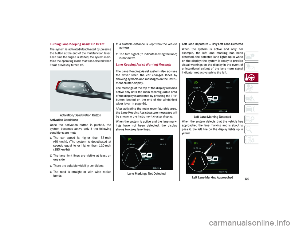
When the system is active and the lane mark -
ings have not been detected, the display
shows two grey lane lines.
Lane Markings Not Detected
Left Lane Departure — Only Left Lane Detected
When the system is active and only, for
example, the left lane marking has been
detected, the detected lane lights up in white
on the display; the system is ready to provide
visual warnings on the display in the event of
unintentional exiting of the lane (turn signal
indicator not activated) to the left.
Left Lane Marking Detected
When the system detects that the vehicle has
approached the lane marking and is about to
pass it, the left line on the display lights up in
yellow.
Left Lane Marking Approached
21_GU_OM_EN_USC_t.book Page 129
Page 135 of 280
133
REFUELING THE VEHICLE
Refueling The Vehicle
Before refueling, make sure that the fuel type
is correct.
Also, stop the engine before refueling.
NOTE:
An inefficient catalytic converter leads to
harmful exhaust emissions, thus contributing
to air pollution.
Refueling Capacity
To ensure that you fill the tank completely, top
off twice after the first click of the fuel nozzle.
Further top-off could cause faults in the fuel
feeding system.
Refueling Procedure
The fuel filler door is unlocked when the
central door locking system is unlocked. It is
automatically locked when the central locking
system is applied.
Opening The Fuel Filler Door
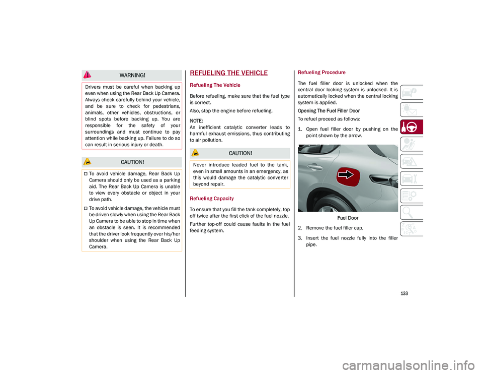
To refuel proceed as follows:
1. Open fuel filler door by pushing on thepoint shown by the arrow.
Fuel Door
2. Remove the fuel filler cap.
3. Insert the fuel nozzle fully into the filler pipe.
WARNING!
Drivers must be careful when backing up
even when using the Rear Back Up Camera.
Always check carefully behind your vehicle,
and be sure to check for pedestrians,
animals, other vehicles, obstructions, or
blind spots before backing up. You are
responsible for the safety of your
surroundings and must continue to pay
attention while backing up. Failure to do so
can result in serious injury or death.
CAUTION!
To avoid vehicle damage, Rear Back Up
Camera should only be used as a parking
aid. The Rear Back Up Camera is unable
to view every obstacle or object in your
drive path.
To avoid vehicle damage, the vehicle must
be driven slowly when using the Rear Back
Up Camera to be able to stop in time when
an obstacle is seen. It is recommended
that the driver look frequently over his/her
shoulder when using the Rear Back Up
Camera.
CAUTION!
Never introduce leaded fuel to the tank,
even in small amounts in an emergency, as
this would damage the catalytic converter
beyond repair.
21_GU_OM_EN_USC_t.book Page 133
Page 137 of 280
135
(Continued)
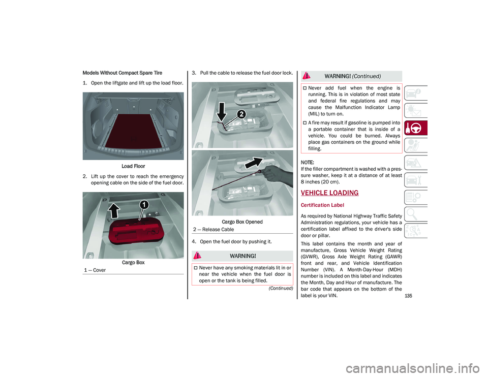
Models Without Compact Spare Tire
1. Open the liftgate and lift up the load floor.Load Floor
2. Lift up the cover to reach the emergency opening cable on the side of the fuel door.
Cargo Box 3. Pull the cable to release the fuel door lock.
Cargo Box Opened
4. Open the fuel door by pushing it.
NOTE:
If the filler compartment is washed with a pres
-
sure washer, keep it at a distance of at least
8 inches (20 cm).
VEHICLE LOADING
Certification Label
As required by National Highway Traffic Safety
Administration regulations, your vehicle has a
certification label affixed to the driver's side
door or pillar.
This label contains the month and year of
manufacture, Gross Vehicle Weight Rating
(GVWR), Gross Axle Weight Rating (GAWR)
front and rear, and Vehicle Identification
Number (VIN). A Month-Day-Hour (MDH)
number is included on this label and indicates
the Month, Day and Hour of manufacture. The
bar code that appears on the bottom of the
label is your VIN.
1 — Cover
2 — Release Cable
WARNING!
Never have any smoking materials lit in or
near the vehicle when the fuel door is
open or the tank is being filled.
Never add fuel when the engine is
running. This is in violation of most state
and federal fire regulations and may
cause the Malfunction Indicator Lamp
(MIL) to turn on.
A fire may result if gasoline is pumped into
a portable container that is inside of a
vehicle. You could be burned. Always
place gas containers on the ground while
filling.
WARNING!
(Continued)
21_GU_OM_EN_USC_t.book Page 135
Page 140 of 280
STARTING AND OPERATING
138
Trailer Towing Weights (Maximum Trailer Weight Ratings)
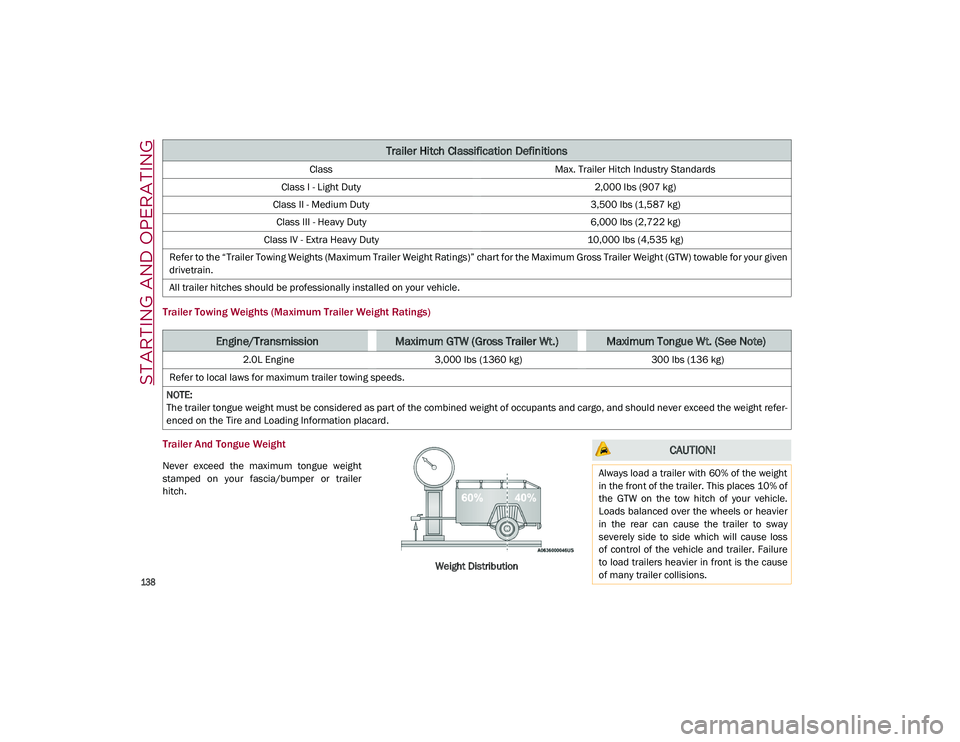
Trailer And Tongue Weight
Never exceed the maximum tongue weight
stamped on your fascia/bumper or trailer
hitch.Weight Distribution
Trailer Hitch Classification Definitions
ClassMax. Trailer Hitch Industry Standards
Class I - Light Duty 2,000 lbs (907 kg)
Class II - Medium Duty 3,500 lbs (1,587 kg)
Class III - Heavy Duty 6,000 lbs (2,722 kg)
Class IV - Extra Heavy Duty 10,000 lbs (4,535 kg)
Refer to the “Trailer Towing Weights (Maximum Trailer Weight Ratings)” chart for the Maximum Gross Trailer Weight (GTW) towable for your given
drivetrain.
All trailer hitches should be professionally installed on your vehicle.
Engine/TransmissionMaximum GTW (Gross Trailer Wt.)Maximum Tongue Wt. (See Note)
2.0L Engine 3,000 lbs (1360 kg) 300 lbs (136 kg)
Refer to local laws for maximum trailer towing speeds.
NOTE:
The trailer tongue weight must be considered as part of the combined weight of occupants and cargo, and should never exceed the weight refer -
enced on the Tire and Loading Information placard.
CAUTION!
Always load a trailer with 60% of the weight
in the front of the trailer. This places 10% of
the GTW on the tow hitch of your vehicle.
Loads balanced over the wheels or heavier
in the rear can cause the trailer to sway
severely side to side which will cause loss
of control of the vehicle and trailer. Failure
to load trailers heavier in front is the cause
of many trailer collisions.
21_GU_OM_EN_USC_t.book Page 138
Page 141 of 280
139
(Continued)
Consider the following items when computing
the weight on the rear axle of the vehicle:
The tongue weight of the trailer.
The weight of any other type of cargo or
equipment put in or on your vehicle.
The weight of the driver and all passengers.
NOTE:
Remember that everything put into or on the
trailer adds to the load on your vehicle. Also,
additional factory-installed options or
dealer-installed options must be considered
as part of the total load on your vehicle. Refer
to the “Tire And Loading Information” placard
for the maximum combined weight of occu -
pants and cargo for your vehicle.
Towing Requirements
To promote proper break-in of your new
vehicle drivetrain components, the following
guidelines are recommended:
Towing Requirements — Tires
Do not attempt to tow a trailer while using a
compact spare tire.
Do not drive more than 50 mph (80 km/h)
when towing while using a full size spare
tire.
Proper tire inflation pressures are essential
to the safe and satisfactory operation of
your vehicle.
Check the trailer tires for proper tire infla -
tion pressures before trailer usage.
Check for signs of tire wear or visible tire
damage before towing a trailer.
Replacing tires with a higher load carrying
capacity will not increase the vehicle's
GVWR and GAWR limits.
For proper tire inflation procedures
Ú
page 233.
WARNING!
Improper towing can lead to a collision.
Follow these guidelines to make your trailer
towing as safe as possible:
Make certain that the load is secured in
the trailer and that it will not shift during
travel. When trailering cargo that is not
fully secured, dynamic load shifts can
occur that may be difficult for the driver to
control. You could lose control of your
vehicle and have a collision.
When hauling cargo, or towing a trailer, do
not overload your vehicle or trailer. Over -
loading can cause a loss of control, poor
performance, or damage to brakes, axle,
engine, transmission, steering, suspen -
sion, chassis structure, or tires.
Safety chains must always be used
between your vehicle and trailer. Always
connect the chains to the frame or hook
retainers of the vehicle hitch. Cross the
chains under the trailer tongue and allow
enough slack for turning corners.
Vehicles with trailers should not be parked
on a grade. When parking, apply the
parking brake on the tow vehicle. Put the
tow vehicle transmission in PARK. Always
block or "chock" the trailer wheels.
GCWR must not be exceeded.
Total weight must be distributed between
the tow vehicle and the trailer such that
the following four ratings are not
exceeded:
• GVWR
• GTW
• GAWR
• Tongue weight rating for the trailer
hitch utilized.
WARNING! (Continued) CAUTION!
Do not tow a trailer at all during the first
500 miles (805 km) the new vehicle is
driven. The engine, axle or other parts
could be damaged.
Then, during the first 500 miles (805 km)
that a trailer is towed, do not drive over
50 mph (80 km/h) and do not make
starts at full throttle. This helps the engine
and other parts of the vehicle wear in at
the heavier loads.
21_GU_OM_EN_USC_t.book Page 139
Page 143 of 280
141
Towing Tips
Before setting out on a trip, practice turning,
stopping, and backing up the trailer in an area
located away from heavy traffic.
Automatic Transmission
Select the DRIVE range when towing. The
transmission controls include a drive strategy
to avoid frequent shifting when towing.
However, if frequent shifting does occur while
in DRIVE, you can use the AutoStick shift
control to manually select a lower gear.
NOTE:
Using a lower gear while operating the vehicle
under heavy loading conditions will improve
performance and extend transmission life by
reducing excessive shifting and heat build-up.
This action will also provide better engine
braking.
Cruise Control — If Equipped
Do not use on hilly terrain or with heavy
loads.
When using the Cruise Control, if you expe-
rience speed drops greater than 10 mph
(16 km/h), disengage until you can get back
to cruising speed.
Use Cruise Control in flat terrain and with
light loads to maximize fuel efficiency.
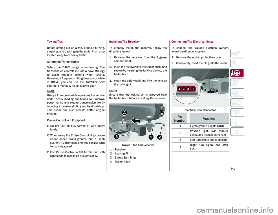
Installing The Receiver
To properly install the receiver, follow the
directions below:
1. Retrieve the receiver from the luggage compartment.
2. Push the receiver into the trailer hitch, and secure by inserting the locking pin into the
trailer hitch.
3. Insert the safety split ring into the hole on the locking pin.
NOTE:
Ensure that the locking pin is removed from
the trailer hitch before installing the receiver.
Trailer Hitch And Receiver
Connecting The Electrical System
To connect the trailer’s electrical system,
follow the directions below:
1. Remove the socket protective cover.
2. Completely insert the plug into the socket.
Electrical Tow Connector
1 – Receiver
2 – Locking Pin
3 – Safety Split Ring
A – Trailer Hitch
Pin
NumberFunction
1 Lights ground (Lights GND)
2 Position light, side marker
lights, and license plate light
3 Left turn signal and stop light
4 Right turn signal and stop
light
21_GU_OM_EN_USC_t.book Page 141