2021 ALFA ROMEO STELVIO wheel
[x] Cancel search: wheelPage 132 of 280
STARTING AND OPERATING
130
NOTE:
The system operates in the same way, but
mirrored, in the event of exiting the right lane
when only the right lane marking has been
detected.
Left Lane Departure — Both Lanes Detected
When the system is active, both lane lines on
the display illuminate in white to indicate the
successful detection of both limits.
When lane markings are detected, the system
is ready to provide indications in case the
driver unintentionally leaves the lane (turn
signal not activated).
As the Lane Keeping Assist system detects the
lane markings while the vehicle is in motion, it
will adjust the display accordingly (from white
to yellow and yellow to white, and increase
their thickness).
If a lane line is crossed, the driver is alerted by
an audible signal as well as the visual indica-
tion in the instrument cluster. The signal is
emitted through the speakers on the side of
the lane marking which is being crossed (e.g.
if the vehicle is exceeding the left line of the
lane, the audible signal will come from the
speakers on the left of the vehicle). Hands Presence On The Steering Wheel
Detection
The system is able to detect the presence of
the driver’s hands on the steering wheel.
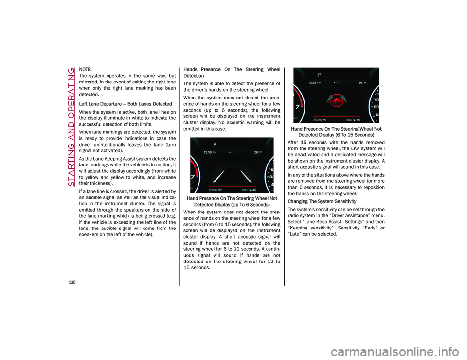
When the system does not detect the pres
-
ence of hands on the steering wheel for a few
seconds (up to 6 seconds), the following
screen will be displayed on the instrument
cluster display. No acoustic warning will be
emitted in this case.
Hand Presence On The Steering Wheel Not Detected Display (Up To 6 Seconds)
When the system does not detect the pres -
ence of hands on the steering wheel for a few
seconds (from 6 to 15 seconds), the following
screen will be displayed on the instrument
cluster display. A short acoustic signal will
sound if hands are not detected on the
steering wheel for 6 to 12 seconds. A contin-
uous signal will sound if hands are not
detect ed on th e steerin g wheel for 12 to
15 seconds. Hand Presence On The Steering Wheel Not
Detected Display (6 To 15 Seconds)
After 15 seconds with the hands removed
from the steering wheel, the LKA system will
be deactivated and a dedicated message will
be shown on the instrument cluster display. A
short acoustic signal will sound in this case.
In any of the situations above where the hands
are removed from the steering wheel for more
than 6 seconds, it is necessary to reposition
the hands on the steering wheel.
Changing The System Sensitivity
The system's sensitivity can be set through the
radio system in the “Driver Assistance” menu.
Select “Lane Keep Assist - Settings” and then
“Keeping sensitivity”. Sensitivity “Early” or
“Late” can be selected.
21_GU_OM_EN_USC_t.book Page 130
Page 134 of 280
STARTING AND OPERATING
132
REAR BACK UP CAMERA /
DYNAMIC GRIDLINES
The Rear Back Up Camera is located on the
liftgate, above the rear license plate.Rear Back Up Camera Location
Camera Activation/Deactivation
To activate the Rear Back Up Camera
features, select “Driver Assistance” from the
Main Menu of the radio system. Under “Driver
Assistance”, Rear Back Up Camera features
can be selected:
View
Camera Delay
Camera Guidelines
Selecting “View” will activate the camera view
on the display. Selecting “Camera Delay” will allow the
camera view to remain on the display shortly
after the vehicle is no longer in REVERSE,
followed by the previously active screen.
Selecting “Camera Guidelines” will activate
the display of the dynamic guidelines that indi
-
cate the route of the vehicle.
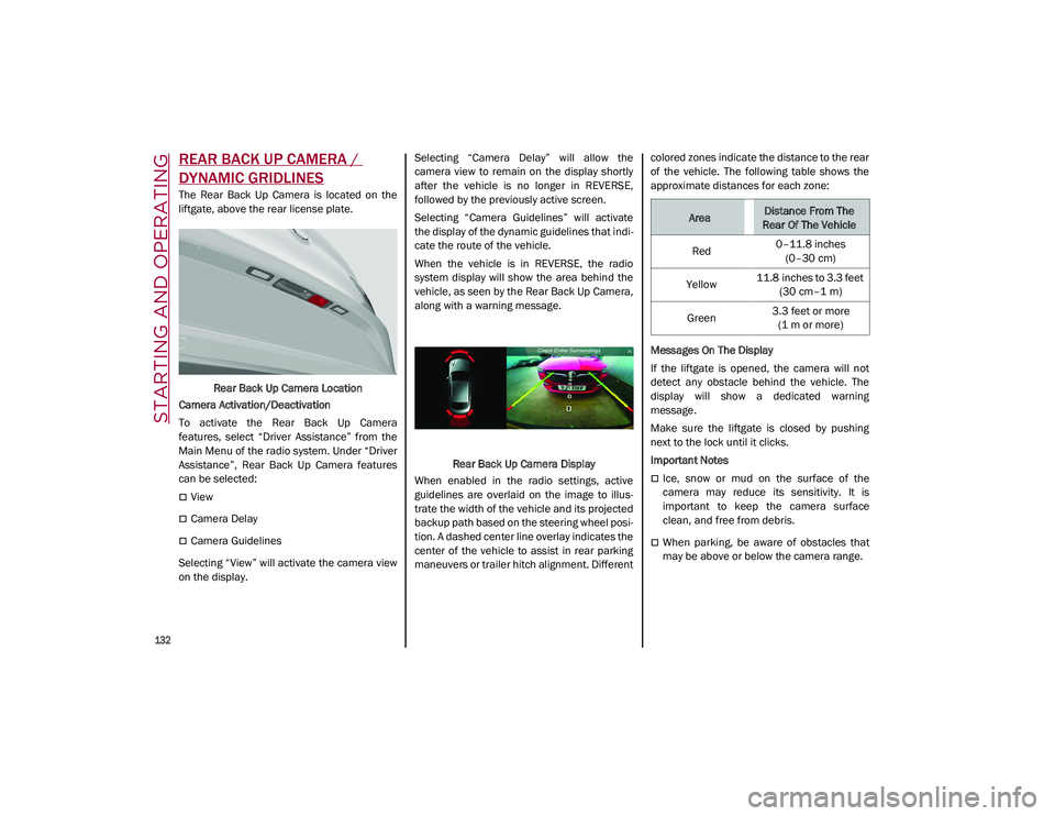
When the vehicle is in REVERSE, the radio
system display will show the area behind the
vehicle, as seen by the Rear Back Up Camera,
along with a warning message.
Rear Back Up Camera Display
When enabled in the radio settings, active
guidelines are overlaid on the image to illus -
trate the width of the vehicle and its projected
backup path based on the steering wheel posi -
tion. A dashed center line overlay indicates the
center of the vehicle to assist in rear parking
maneuvers or trailer hitch alignment. Different colored zones indicate the distance to the rear
of the vehicle. The following table shows the
approximate distances for each zone:
Messages On The Display
If the liftgate is opened, the camera will not
detect any obstacle behind the vehicle. The
display will show a dedicated warning
message.
Make sure the liftgate is closed by pushing
next to the lock until it clicks.
Important Notes
Ice, snow or mud on the surface of the
camera may reduce its sensitivity. It is
important to keep the camera surface
clean, and free from debris.
When parking, be aware of obstacles that
may be above or below the camera range.
AreaDistance From The
Rear Of The Vehicle
Red 0–11.8 inches
(0–30 cm)
Yellow 11.8 inches to 3.3 feet
(30 cm–1 m)
Green 3.3 feet or more
(1 m or more)
21_GU_OM_EN_USC_t.book Page 132
Page 138 of 280
STARTING AND OPERATING
136
Gross Vehicle Weight Rating (GVWR)
The GVWR is the total permissible weight of
your vehicle including driver, passengers,
vehicle, options and cargo. The label also
specifies maximum capacities of front and
rear axle systems (GAWR). Total load must be
limited so GVWR and front and rear GAWR are
not exceeded.
Payload
The payload of a vehicle is defined as the
allowable load weight a truck can carry,
including the weight of the driver, all passen-
gers, options and cargo.
Gross Axle Weight Rating (GAWR)
The GAWR is the maximum permissible load
on the front and rear axles. The load must be
distributed in the cargo area so that the GAWR
of each axle is not exceeded.
Each axle GAWR is determined by the compo -
nents in the system with the lowest load
carrying capacity (axle, springs, tires or
wheels). Heavier axles or suspension compo -
nents sometimes specified by purchasers for
increased durability do not necessarily
increase the vehicle's GVWR.
Tire Size
The tire size on the Vehicle Certification Label
represents the actual tire size on your vehicle.
Replacement tires must be equal to the load
capacity of this tire size.
Rim Size
This is the rim size that is appropriate for the
tire size listed.
Inflation Pressure
This is the cold tire inflation pressure for your
vehicle for all loading conditions up to full
GAWR.
Curb Weight
The curb weight of a vehicle is defined as the
total weight of the vehicle with all fluids,
including vehicle fuel, at full capacity condi -
tions, and with no occupants or cargo loaded
into the vehicle. The front and rear curb weight
values are determined by weighing your
vehicle on a commercial scale before any
occupants or cargo are added.
Loading
The actual total weight and the weight of the
front and rear of your vehicle at the ground can
best be determined by weighing it when it is
loaded and ready for operation.
The entire vehicle should first be weighed on a
commercial scale to ensure that the GVWR
has not been exceeded. The weight on the
front and rear of the vehicle should then be
determined separately to be sure that the load
is properly distributed over the front and rear
axle. Weighing the vehicle may show that the
GAWR of either the front or rear axles has
been exceeded but the total load is within the specified GVWR. If so, weight must be shifted
from front to rear or rear to front as appro
-
priate until the specified weight limitations are
met. Store the heavier items down low and be
sure that the weight is distributed equally.
Stow all loose items securely before driving.
Improper weight distributions can have an
adverse effect on the way your vehicle steers
and handles and the way the brakes operate.
TRAILER TOWING
In this section you will find safety tips and
information on limits to the type of towing you
can reasonably do with your vehicle. Before
towing a trailer, carefully review this informa -
tion to tow your load as efficiently and safely
as possible.
To maintain the New Vehicle Limited Warranty
coverage, follow the requirements and recom -
mendations in this manual concerning vehi -
cles used for trailer towing.
CAUTION!
Do not load your vehicle any heavier than
the GVWR or the maximum front and rear
GAWR. If you do, parts on your vehicle can
break, or it can change the way your vehicle
handles. This could cause you to lose
control. Also overloading can shorten the
life of your vehicle.
21_GU_OM_EN_USC_t.book Page 136
Page 140 of 280
STARTING AND OPERATING
138
Trailer Towing Weights (Maximum Trailer Weight Ratings)
Trailer And Tongue Weight
Never exceed the maximum tongue weight
stamped on your fascia/bumper or trailer
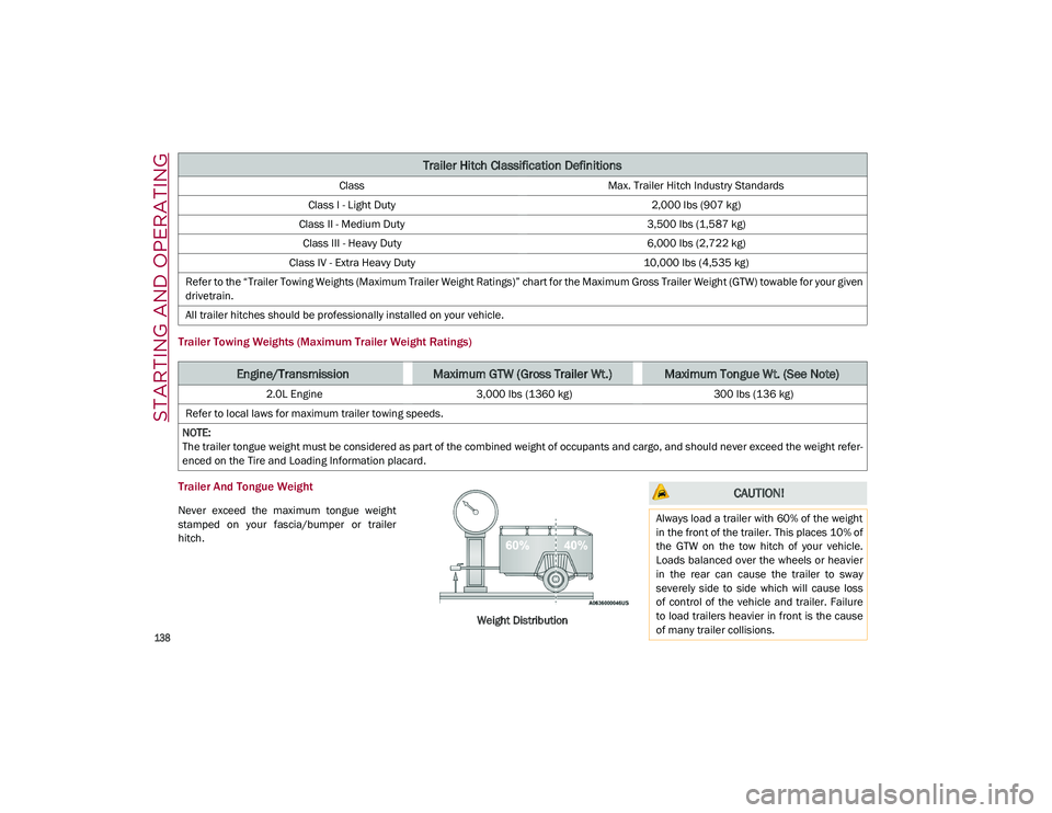
hitch.Weight Distribution
Trailer Hitch Classification Definitions
ClassMax. Trailer Hitch Industry Standards
Class I - Light Duty 2,000 lbs (907 kg)
Class II - Medium Duty 3,500 lbs (1,587 kg)
Class III - Heavy Duty 6,000 lbs (2,722 kg)
Class IV - Extra Heavy Duty 10,000 lbs (4,535 kg)
Refer to the “Trailer Towing Weights (Maximum Trailer Weight Ratings)” chart for the Maximum Gross Trailer Weight (GTW) towable for your given
drivetrain.
All trailer hitches should be professionally installed on your vehicle.
Engine/TransmissionMaximum GTW (Gross Trailer Wt.)Maximum Tongue Wt. (See Note)
2.0L Engine 3,000 lbs (1360 kg) 300 lbs (136 kg)
Refer to local laws for maximum trailer towing speeds.
NOTE:
The trailer tongue weight must be considered as part of the combined weight of occupants and cargo, and should never exceed the weight refer -
enced on the Tire and Loading Information placard.
CAUTION!
Always load a trailer with 60% of the weight
in the front of the trailer. This places 10% of
the GTW on the tow hitch of your vehicle.
Loads balanced over the wheels or heavier
in the rear can cause the trailer to sway
severely side to side which will cause loss
of control of the vehicle and trailer. Failure
to load trailers heavier in front is the cause
of many trailer collisions.
21_GU_OM_EN_USC_t.book Page 138
Page 141 of 280
139
(Continued)
Consider the following items when computing
the weight on the rear axle of the vehicle:
The tongue weight of the trailer.
The weight of any other type of cargo or
equipment put in or on your vehicle.
The weight of the driver and all passengers.
NOTE:
Remember that everything put into or on the
trailer adds to the load on your vehicle. Also,
additional factory-installed options or
dealer-installed options must be considered
as part of the total load on your vehicle. Refer
to the “Tire And Loading Information” placard
for the maximum combined weight of occu -
pants and cargo for your vehicle.
Towing Requirements
To promote proper break-in of your new
vehicle drivetrain components, the following
guidelines are recommended:
Towing Requirements — Tires
Do not attempt to tow a trailer while using a
compact spare tire.
Do not drive more than 50 mph (80 km/h)
when towing while using a full size spare
tire.
Proper tire inflation pressures are essential
to the safe and satisfactory operation of
your vehicle.
Check the trailer tires for proper tire infla -
tion pressures before trailer usage.
Check for signs of tire wear or visible tire
damage before towing a trailer.
Replacing tires with a higher load carrying
capacity will not increase the vehicle's
GVWR and GAWR limits.
For proper tire inflation procedures
Ú
page 233.
WARNING!
Improper towing can lead to a collision.
Follow these guidelines to make your trailer
towing as safe as possible:
Make certain that the load is secured in
the trailer and that it will not shift during
travel. When trailering cargo that is not
fully secured, dynamic load shifts can
occur that may be difficult for the driver to
control. You could lose control of your
vehicle and have a collision.
When hauling cargo, or towing a trailer, do
not overload your vehicle or trailer. Over -
loading can cause a loss of control, poor
performance, or damage to brakes, axle,
engine, transmission, steering, suspen -
sion, chassis structure, or tires.
Safety chains must always be used
between your vehicle and trailer. Always
connect the chains to the frame or hook
retainers of the vehicle hitch. Cross the
chains under the trailer tongue and allow
enough slack for turning corners.
Vehicles with trailers should not be parked
on a grade. When parking, apply the
parking brake on the tow vehicle. Put the
tow vehicle transmission in PARK. Always
block or "chock" the trailer wheels.
GCWR must not be exceeded.
Total weight must be distributed between
the tow vehicle and the trailer such that
the following four ratings are not
exceeded:
• GVWR
• GTW
• GAWR
• Tongue weight rating for the trailer
hitch utilized.
WARNING! (Continued) CAUTION!
Do not tow a trailer at all during the first
500 miles (805 km) the new vehicle is
driven. The engine, axle or other parts
could be damaged.
Then, during the first 500 miles (805 km)
that a trailer is towed, do not drive over
50 mph (80 km/h) and do not make
starts at full throttle. This helps the engine
and other parts of the vehicle wear in at
the heavier loads.
21_GU_OM_EN_USC_t.book Page 139
Page 145 of 280
143
Traffic And Road Conditions
High fuel consumption is caused by heavy
traffic, for instance when traveling in traffic
with frequent use of low gears or in cities with
many traffic lights. Winding mountain roads
and rough road surfaces also adversely affect
consumption.
Stops In Traffic
During prolonged stops (e.g. railway cross-
ings), turn off the engine.
Performance — Quadrifoglio
This vehicle is equipped with an engine
capable of delivering exceptionally fast accel -
eration and speed:
Peak power: 505 HP at 6,500 RPM.
Peak torque: 443 ft-lbs at 2,500–5,000 RPM.
Top speed: 176 mph (283 km/h).
Acceleration from 0 to 60 mph (0 to 100 km/h):
3.6 seconds.
For safe driving, it is essential, particularly
during the first days of use, to get to know the
car by driving carefully and gradually discov -
ering its performance.
Brakes
The car braking system may be available with
four carbon-ceramic material brake discs, one
on each wheel. In order to guarantee the maximum braking
capacity for the first use, Alfa Romeo performs
a "run-in" procedure for discs and pads directly
at the factory.
The use of carbon-ceramic material brake
discs guarantees braking features (better
deceleration/pedal load ratio, braking
distances, fading resistance) proportional to
the dynamic features of the car in addition to
considerably decreasing the unsprung compo
-
nent weight.
The materials used and the structural features
of the system could generate unusual noises
which have absolutely no adverse effect on
correct operation and reliability of the braking
system.
Greater pressure may need to be applied to
the brake pedal the first time to keep the same
braking capacities in presence of condensa -
tion or salt on the braking surfaces, for
example after washing or if the car is not used
for a long time.
NOTE:
Given the high technological level of this
system, any servicing on it must be performed
by an authorized dealer which exclusively has
the skills needed for the repair and mainte -
nance operations. In case of intensive, high-performance use of
the car, have the efficiency of the
carbon-ceramic material braking system
inspected as shown on the Maintenance Plan
at an authorized dealer.
Driving On Race Tracks
Before driving on a track using a racing style, it
is necessary to:
Attend a race track driving course.
Check the liquid levels in the engine
compartment
Ú
page 208.
Have the car inspected at an authorized
dealer.
Remember that the car was not designed to be
driven exclusively on the race track and that
this use increases stress and component
wear.
NOTE:
Quadrifoglio front brakes are equipped with
Non-Asbestos Organic (NAO) type pads. These
pads are NOT suitable for high thermal loads
(for example track use). If you want to use
vehicle on a track it is recommended to use
the optional CCM Brakes (Carbon Ceramic
Brake disc).
21_GU_OM_EN_USC_t.book Page 143
Page 147 of 280
145
(Continued)
SAFETY
This very important section describes the
safety systems that your vehicle may be
equipped with, and provides instructions on
how to use them correctly.
ACTIVE SAFETY SYSTEMS
The vehicle may be equipped with the
following active safety devices:
Anti-Lock Brake System (ABS)
Active Torque Vectoring (ATV) System
Dynamic Steering Torque (DST) System
Drive Train Control (DTC) System
Electronic Stability Control (ESC) System
Hill Descent Control (HDC) System
Hill Start Assist (HSA) System
Panic Brake Assist (PBA) System
Traction Control System (TCS)
For system operation, see the following pages.
Anti-Lock Brake System (ABS)
An integral part of the braking system, the ABS
prevents one or more wheels from locking and
slipping in all road surface conditions, regard -
less of the intensity of the braking action. The
system ensures that the vehicle can be
controlled even during emergency braking,
allowing the driver to optimize stopping
distances. The system intervenes during braking when
the wheels are about to lock, typically in emer
-
gency braking or low-grip conditions where
locking may be more frequent.
The system also improves control and stability
of the vehicle when braking on a surface
where the grip of the left and right wheels
varies, such as in a corner.
The Electronic Braking Force Distribution
(EBD) system works with the ABS, allowing the
brake force to be distributed between the front
and rear wheels.
System Intervention
The ABS equipped on this vehicle is provided
with the "Brake-By-Wire", Integrated Brake
System (IBS), function. With this system, the
command given by pressing the brake pedal is
not transmitted hydraulically, but electrically.
Therefore, the light pulsation that is felt on the
pedal with the traditional system is no longer
noticeable.Active Torque Vectoring (ATV) System — If
Equipped
The dynamic drive control is used to optimize
and balance the drive torque between the
wheels of the same axles. The ATV system
improves the grip in turns, sending more drive
torque to the external wheel.
WARNING!
The ABS contains sophisticated electronic
equipment that may be susceptible to
interference caused by improperly
installed or high output radio transmitting
equipment. This interference can cause
possible loss of anti-lock braking capa -
bility. Installation of such equipment
should be performed by qualified profes -
sionals.
Pumping of the Anti-Lock Brakes will
diminish their effectiveness and may lead
to a collision. Pumping makes the stop -
ping distance longer. Just press firmly on
your brake pedal when you need to slow
down or stop.
The ABS cannot prevent the natural laws
of physics from acting on the vehicle, nor
can it increase braking or steering effi -
ciency beyond that afforded by the condi -
tion of the vehicle brakes and tires or the
traction afforded.
The ABS cannot prevent collisions,
including those resulting from excessive
speed in turns, following another vehicle
too closely, or hydroplaning.
The capabilities of an ABS equipped
vehicle must never be exploited in a reck -
less or dangerous manner that could jeop -
ardize the user’s safety or the safety of
others.
WARNING! (Continued)
21_GU_OM_EN_USC_t.book Page 145
Page 148 of 280
SAFETY
146
Given that, in a turn, the external wheels of the
car travel more than the internal ones and
therefore turn faster, sending a higher thrust
to the external rear wheel allows for the car to
be more stable and to not suffer an "under-
steer" condition. Understeer occurs when the
vehicle is turning less than appropriate for the
steering wheel position.
Dynamic Steering Torque (DST) System
DST uses the integration of the Electronic
Stability Control (ESC) system with the electric
power steering to increase the safety level of
the whole vehicle.
In critical situations (e.g. braking on surfaces
with different grip conditions), the ESC system
influences the steering through the DST func -
tion to implement an additional torque contri -
bution on the steering wheel in order to
suggest the most correct maneuver to the
driver.
The coordinated action of the brakes and
steering increases the safety and control of
the vehicle.
NOTE:
The DST feature is only meant to help the
driver realize the correct course of action
through small torques on the steering wheel,
which means the effectiveness of the DST
feature is highly dependent on the driver’s
sensitivity and overall reaction to the applied
torque. It is very important to realize that this feature will not steer the vehicle, meaning the
driver is still responsible for steering the
vehicle.
Drive Train Control (DTC) System
Some models of this vehicle are equipped with
an All-Wheel Drive (AWD) system, which offers
an optimal drive for countless driving condi
-
tions and road surfaces. The system reduces
tire slipping to a minimum, automatically
redistributing the torque to the front and rear
wheels as needed.
To maximize fuel savings, the vehicle with
AWD automatically passes to Rear-Wheel
Drive (RWD) when the road and environmental
conditions are such that they wouldn't cause
the tires to slip. When the road and environ -
mental conditions require better traction, the
vehicle automatically switches to AWD mode.
NOTE:
There may be a brief delay in shifting to
AWD mode after a tire slipping event occurs.
If the system failure symbol switches on,
after starting the engine or while driving, it
means that the AWD system is not working
properly. If the warning message activates
frequently, it is recommended to carry out
the maintenance operations.
Electronic Stability Control (ESC) System
The ESC system improves the directional
control and stability of the vehicle in various
driving conditions.
The ESC system corrects the vehicle’s under -
steer and oversteer, distributing the brake
force on the appropriate wheels. The torque
supplied by the engine can also be reduced in
order to maintain control of the vehicle.
The ESC system uses sensors installed on the
vehicle to determine the path that the driver
intends to follow and compares it with the
vehicle’s effective path. When the real path
deviates from the desired path, the ESC
system intervenes to counter the vehicle’s
oversteer or understeer.
Oversteer occurs when the vehicle is
turning more than it should according to the
angle of the steering wheel.
Understeer occurs when the vehicle is
turning less than it should according to the
angle of the steering wheel.
System Intervention
The intervention of the system is indicated by
the flashing of the ESC warning light on the
instrument panel, to inform the driver that the
vehicle stability and grip are critical.
21_GU_OM_EN_USC_t.book Page 146