2021 ALFA ROMEO STELVIO wheel
[x] Cancel search: wheelPage 192 of 280
SAFETY
190
(Continued)
(Continued)
Periodic Safety Checks You Should Make
Outside The Vehicle
Tires
Examine tires for excessive tread wear and
uneven wear patterns. Check for stones, nails,
glass, or other objects lodged in the tread or
sidewall. Inspect the tread for cuts and cracks.
Inspect sidewalls for cuts, cracks, and bulges.
Check the wheel nuts for tightness. Check the
tires (including spare) for proper cold inflation
pressure.
Lights
Have someone observe the operation of brake
lights and exterior lights while you work the controls. Check turn signal and high beam
indicator lights on the instrument panel.
Door Latches
Check for proper closing, latching, and locking.
Fluid Leaks
Check area under the vehicle after overnight
parking for fuel, coolant, oil, or other fluid
leaks. Also, if gasoline fumes are detected or if
fuel, or brake fluid leaks are suspected, the
cause should be located and corrected imme
-
diately.
Exhaust Gas
ONLY use the driver’s side floor mat on the
driver’s side floor area. To check for inter -
ference, with the vehicle properly parked
with the engine off, fully depress the
accelerator, the brake, and the clutch
pedal (if present) to check for interfer -
ence. If your floor mat interferes with the
operation of any pedal, or is not secure to
the floor, remove the floor mat from the
vehicle and place the floor mat in your
trunk.
ONLY use the passenger’s side floor mat
on the passenger’s side floor area.
ALWAYS make sure objects cannot fall or
slide into the driver’s side floor area when
the vehicle is moving. Objects can become
trapped under accelerator, brake, or
clutch pedals and could cause a loss of
vehicle control.
NEVER place any objects under the floor
mat (e.g., towels, keys, etc.). These
objects could change the position of the
floor mat and may cause interference with
the accelerator, brake, or clutch pedals.
WARNING! (Continued)
If the vehicle carpet has been removed
and re-installed, always properly attach
carpet to the floor and check the floor mat
fasteners are secure to the vehicle carpet.
Fully depress each pedal to check for
interference with the accelerator, brake,
or clutch pedals then re-install the floor
mats.
It is recommended to only use mild soap
and water to clean your floor mats. After
cleaning, always check your floor mat has
been properly installed and is secured to
your vehicle using the floor mat fasteners
by lightly pulling mat.
WARNING! (Continued)
WARNING!
Exhaust gases can injure or kill. They
contain carbon monoxide (CO), which is
colorless and odorless. Breathing it can
make you unconscious and can eventually
poison you. To avoid breathing (CO), follow
these safety tips:
Do not run the engine in a closed garage
or in confined areas any longer than
needed to move your vehicle in or out of
the area.
If you are required to drive with the trunk/lift -
gate/rear doors open, make sure that all
windows are closed and the climate control
BLOWER switch is set at high speed. DO NOT
use the recirculation mode.
21_GU_OM_EN_USC_t.book Page 190
Page 197 of 280
195
(Continued)
Frequently Asked Questions:
What happens if I accidentally push the SOS -
Emergency Call Button? You have 10 seconds
after pushing the emergency button to cancel
the call. To cancel the call, push the button
again.
What type of information is sent when I make
an SOS - Emergency Call from my vehicle?
Certain vehicle information, such as the VIN, is
transmitted along with last known GPS loca-
tion. Also note that emergency service opera -
tors may record conversations and sounds
within your vehicle once a connection is made,
and by using the service you consent to having
this information shared.
When can I use the SOS - Emergency
Call button? You can ONLY use the
SOS - Emergency Call button to
make a call if you or someone else
needs emergency assistance.
JACKING AND TIRE CHANGING
General Instructions
This vehicle can be equipped with a Tire
Service Kit
Ú
page 198.
As an alternative to the Tire Service Kit, the
vehicle may be purchased with a compact
spare tire
Ú
page 196.
Jack Information And Usage Precautions
Jack Information
The jack weighs 4.4 lb (2 kg).
The jack requires no adjustment.
The jack cannot be repaired, and in the
event of a fault it must be replaced by
another factory replacement.
No tool other than its extension lever may
be fitted on the jack.
Jack Maintenance
Prevent any dirt from depositing on the
"worm screw".
Keep the "worm screw" lubricated.
Never modify the jack.
Conditions Of Non-Use Of The Jack
Temperatures below −40°F (−40°C).
On sandy or muddy ground
On uneven ground
On steep slopes in extreme weather condi -
tions.
In direct contact with the engine or for
repairs under the vehicle
On boats
WARNING!
Do not attempt to change a tire on the
side of the vehicle close to moving traffic.
Pull far enough off the road to avoid the
danger of being hit when operating the
jack or changing the wheel.
Being under a jacked-up vehicle is
dangerous. The vehicle could slip off the
jack and fall on you. You could be crushed.
Never put any part of your body under a
vehicle that is on a jack. If you need to get
under a raised vehicle, take it to a service
center where it can be raised on a lift.
Never start or run the engine while the
vehicle is on a jack.
The jack is designed to be used as a tool
for changing tires only. The jack should
not be used to lift the vehicle for service
purposes. The vehicle should be jacked on
a firm level surface only. Avoid ice or slip -
pery areas.
WARNING! (Continued)
21_GU_OM_EN_USC_t.book Page 195
Page 198 of 280
IN CASE OF EMERGENCY
196
Changing Procedure
1. Park the vehicle on a firm, level surface.Avoid ice or slippery areas.
2. Turn on the Hazard Warning Flashers.
3. Apply the electric park brake.
4. Place the gear selector into PARK (P).
5. Place the ignition in the OFF mode.
6. Block both the front and rear of the wheel diagonally opposite of the jacking position.
For example, if changing the right front
tire, block the left rear wheel.
Wheels Blocked 7. Open the liftgate and lift up the load floor
using the handle.
8. Take the warning triangle and position it at a suitable distance from the vehicle to
warn oncoming vehicles.
9. Unscrew the locking plate and take out the compact spare tire and the air
compressor.
Compact Spare Tire — If Equipped
10. Remove the damaged wheel by using the wheel wrench to loosen the bolts by one
turn.
11. Position the jack under the vehicle, near the wheel to be changed, taking care not
to damage the plastic body panel.
12. Lift the extension lever on the wrench. Jacking Location
WARNING!
Do not attempt to change a tire on the side
of the vehicle close to moving traffic. Pull
far enough off the road to avoid being hit
when operating the jack or changing the
wheel.
1 — Locking Plate
2 — Extension Lever
3 — Wrench Head
4 — Jack
5 — Lifting Block
21_GU_OM_EN_USC_t.book Page 196
Page 199 of 280

197
13. Rotate the extension lever clockwise untilthe round pin on the jack engages in the
hole in the lifting block located about
6 inches (15 cm) from the outside edge of
the body. The lifting points are marked by
triangles visible on the plastic body
panel.
Jacking Point Indicators
14. Raise the vehicle by turning the jack screw clockwise, using the swivel wrench. Raise
the vehicle only until the tire just clears the
surface and enough clearance is obtained
to install the compact spare tire. Minimum
tire lift provides maximum stability. 15. Remove the five wheel bolts and take the
wheel off.
16. Make sure the contact surfaces between compact spare tire and hub are clean so
that the fastening bolts will not come
loose.
17. Fit the compact spare tire by inserting the first wheel bolt for two threads into the
hole closest to the valve.
18. Take the wheel wrench and tighten the wheel bolts.
19. Inflate the compact spare tire by removing the cap from its inflation valve and
screwing on the compressor inflation hose
fitting. 20. Make sure that the switch on the
compressor is in the (off) O position, open
the liftgate and insert the plug into the
power socket in the cargo area, or on the
center console and start the engine. Place
the on/off switch in the (on) I position.
Attaching Compressor To Tire
21. Inflate the compact spare tire to a pres -
sure of 43.5 psi (3 bar).
NOTE:
If spare tire is overinflated, be sure to lower
the psi in the tire to the recommended amount
by using the deflation button on the air
compressor.
22. Operate the wheel wrench on the jack to lower the vehicle.
CAUTION!
Do not attempt to raise the vehicle by
jacking on locations other than those
indicated in the Jacking Instructions for this
vehicle.
WARNING!
Raising the vehicle higher than necessary
can make the vehicle less stable. It could
slip off the jack and hurt someone near it.
Raise the vehicle only enough to remove
the tire.
CAUTION!
Be sure to mount the spare tire with the
valve stem facing outward. The vehicle
could be damaged if the spare tire is
mounted incorrectly.
6 — Air Compressor
7 — Pressure Gauge
8 — Power Button
21_GU_OM_EN_USC_t.book Page 197
Page 200 of 280
IN CASE OF EMERGENCY
198
23. Remove the jack.
24. Use the wheel wrench to fully tighten thebolts, passing alternately from one bolt to
the diagonally opposite one.
To obtain a more accurate reading, it is advis -
able to check the pressure of the compact
spare tire on the pressure gauge with the
compressor off.
NOTE:
Do not stow the deflated tire in the compact
spare tire location.
The compressor was designed for inflating the
compact spare tire. Do not use it for inflating
mattresses, rafts, etc.
NOTE:
Spare tires are intended for temporary use
only.
Have the full-sized tire repaired or replaced, as
soon as possible.
TIRE SERVICE KIT — IF
EQUIPPED
Description
If a tire is punctured, you can make an emer -
gency repair using the Tire Service Kit located
in the rear storage area under the load plat -
form.
1. Stop the vehicle in a position where you can repair the tire safely. You should be as
far as possible from the side of the road,
and in a position that is not dangerous for
oncoming traffic. Turn on the Hazard
Warning Flashers, remove the safety
triangle from the luggage compartment,
and place it at a suitable distance from the
vehicle to make other drivers aware of
your presence.
2. Verify that the valve stem (on the wheel with the deflated tire) is in a position that
is near to the ground. This will allow the tire repair kit hoses to reach the valve stem
and keep the tire service kit flat on the
ground.
3. Place the gear selector in PARK (P).
4. Apply the electric park brake and turn the engine OFF.
To access the Tire Service Kit, open the liftgate
and lift the load floor.
Load Floor
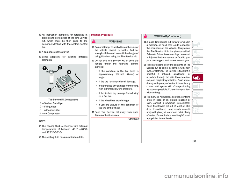
The Tire Service Kit consists of:
Sealant cartridge containing the sealing
fluid
Filler Tube
Air compressor, complete with pressure
gauge and connectors
Adhesive label with the writing "Max.
50 mph (80 km/h)”, to be attached in a
position easily visible to the driver (e.g. on
the dashboard) after repairing the tire
WARNING!
To avoid the risk of forcing the vehicle off
the jack, do not tighten the wheel nuts fully
until the vehicle has been lowered. Failure
to follow this warning may result in serious
injury.
WARNING!
A loose tire or jack thrown forward in a
collision or hard stop could endanger the
occupants of the vehicle. Always stow the
jack parts and the spare tire in the places
provided. Have the deflated (flat) tire
repaired or replaced immediately.
21_GU_OM_EN_USC_t.book Page 198
Page 201 of 280
199
(Continued)
An instruction pamphlet for reference in
prompt and correct use of the Tire Service
Kit, which must be then given to the
personnel dealing with the sealant-treated
tire
A pair of protective gloves
Some adapters, for inflating different
elementsTire Service Kit Components
NOTE:
The sealing fluid is effective with external
temperatures of between -40°F (-40°C)
and 122°F (50°C).
The sealing fluid has an expiration date.
Inflation Procedure
1 — Sealant Cartridge
2 — Filling Hose
3 — Adhesive Label
4 — Air Compressor
WARNING!
Do not attempt to seal a tire on the side of
the vehicle closest to traffic. Pull far
enough off the road to avoid the danger of
being hit when using the Tire Service Kit.
Do not use Tire Service Kit or drive the
vehicle under the following circum -
stances:
• If the puncture in the tire tread is
approximately 1/4 inch (6 mm) or
larger.
• If the tire has any sidewall damage.
• If the tire has any damage from driving
with extremely low tire pressure.
• If the tire has any damage from driving
on a flat tire.
• If the wheel has any damage.
• If you are unsure of the condition of
the tire or the wheel.
Keep Tire Service Kit away from open
flames or heat sources.
A loose Tire Service Kit thrown forward in
a collision or hard stop could endanger
the occupants of the vehicle. Always stow
the Tire Service Kit in the place provided.
Failure to follow these warnings can result
in injuries that are serious or fatal to you,
your passengers, and others around you.
Take care not to allow the contents of Tire
Service Kit to come in contact with hair,
eyes, or clothing. Tire Service Kit sealant is
harmful if inhaled, swallowed, or
absorbed through the skin. It causes skin,
eye, and respiratory irritation. Flush imme -
diately with plenty of water if there is any
contact with eyes or skin. Change clothing
as soon as possible, if there is any contact
with clothing.
Tire Service Kit Sealant solution contains
latex. In case of an allergic reaction or
rash, consult a physician immediately.
Keep Tire Service Kit out of reach of chil -
dren. If swallowed, rinse mouth immedi -
ately with plenty of water and drink plenty
of water. Do not induce vomiting! Consult
a physician immediately.
WARNING! (Continued)
21_GU_OM_EN_USC_t.book Page 199
Page 203 of 280
201
11. Apply the adhesive label from the sealantbottle where it can be easily seen by the
driver as a reminder that the tire has been
treated with a Tire Service Kit, as well as
not to exceed the speed restriction for the
treated tire.
NOTE:
Only use original sealant cartridges, which can
be purchased at an authorized dealer.
Checking And Restoring Tire Pressure
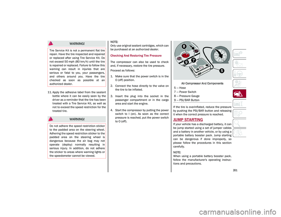
The compressor can also be used to check
and, if necessary, restore the tire pressure.
Proceed as follows:
1. Make sure that the power switch is in the
O (off) position.
2. Connect the hose directly to the valve on the tire to be inflated.
3. Insert the plug into the socket in the passenger compartment or in the cargo
area and start the engine.
4. Start the compressor by putting the power switch to I (on). As soon as the correct
pressure is reached, put the power switch
to O (off). Air Compressor And Components
If the tire is overinflated, reduce the pressure
by pushing the PSI/BAR button and releasing
it when the correct pressure is reached.
JUMP STARTING
If your vehicle has a discharged battery, it can
be jump started using a set of jumper cables
and a battery in another vehicle, or by using a
portable battery booster pack. Jump starting
can be dangerous if done improperly, so
please follow the procedures in this section
carefully.
NOTE:
When using a portable battery booster pack,
follow the manufacturer's operating instruc -
tions and precautions.
WARNING!
Tire Service Kit is not a permanent flat tire
repair. Have the tire inspected and repaired
or replaced after using Tire Service Kit. Do
not exceed 50 mph (80 km/h) until the tire
is repaired or replaced. Failure to follow this
warning can result in injuries that are
serious or fatal to you, your passengers,
and others around you. Have the tire
checked as soon as possible at an
authorized dealer.
WARNING!
Do not adhere the speed restriction sticker
to the padded area on the steering wheel.
Adhering the speed restriction sticker to the
padded area on the steering wheel is
dangerous because the air bag may not
operate (deploy) normally resulting in
serious injury. In addition, do not adhere
the sticker to areas where warning lights or
the speedometer cannot be viewed.
5 — Hose
7 — Power Switch
8 — Pressure Gauge
9 — PSI/BAR Button
21_GU_OM_EN_USC_t.book Page 201
Page 207 of 280
205
(Continued)
MANUAL PARK RELEASE
See an authorized dealer to disengage the
manual park release lever.
TOWING A DISABLED VEHICLE
This section describes procedures for towing a
disabled vehicle using a commercial towing
service.
NOTE:
If your vehicle is equipped with a Anti-Lift
Protection system, you will need to disable the
system prior to towing by pushing the button
located on the overhead console
Ú
page 23.
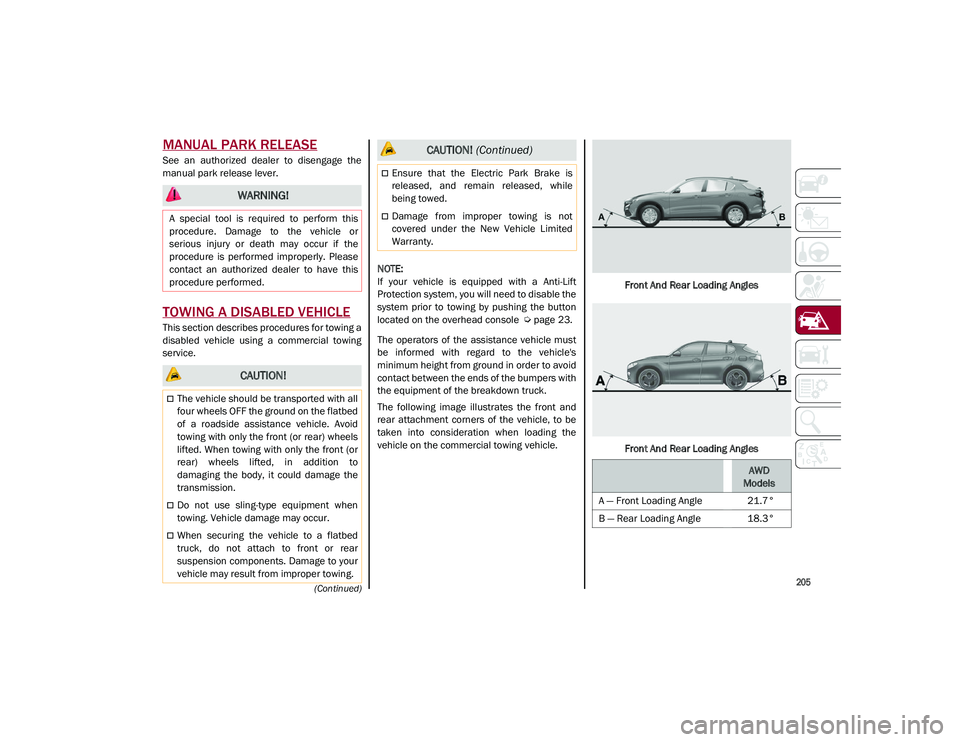
The operators of the assistance vehicle must
be informed with regard to the vehicle's
minimum height from ground in order to avoid
contact between the ends of the bumpers with
the equipment of the breakdown truck.
The following image illustrates the front and
rear attachment corners of the vehicle, to be
taken into consideration when loading the
vehicle on the commercial towing vehicle. Front And Rear Loading Angles
Front And Rear Loading Angles
WARNING!
A special tool is required to perform this
procedure. Damage to the vehicle or
serious injury or death may occur if the
procedure is performed improperly. Please
contact an authorized dealer to have this
procedure performed.
CAUTION!
The vehicle should be transported with all
four wheels OFF the ground on the flatbed
of a roadside assistance vehicle. Avoid
towing with only the front (or rear) wheels
lifted. When towing with only the front (or
rear) wheels lifted, in addition to
damaging the body, it could damage the
transmission.
Do not use sling-type equipment when
towing. Vehicle damage may occur.
When securing the vehicle to a flatbed
truck, do not attach to front or rear
suspension components. Damage to your
vehicle may result from improper towing.
Ensure that the Electric Park Brake is
released, and remain released, while
being towed.
Damage from improper towing is not
covered under the New Vehicle Limited
Warranty.
CAUTION! (Continued)
AWD
Models
A — Front Loading Angle 21.7°
B — Rear Loading Angle 18.3°
21_GU_OM_EN_USC_t.book Page 205