2021 ALFA ROMEO STELVIO check engine light
[x] Cancel search: check engine lightPage 145 of 280
143
Traffic And Road Conditions
High fuel consumption is caused by heavy
traffic, for instance when traveling in traffic
with frequent use of low gears or in cities with
many traffic lights. Winding mountain roads
and rough road surfaces also adversely affect
consumption.
Stops In Traffic
During prolonged stops (e.g. railway cross-
ings), turn off the engine.
Performance — Quadrifoglio
This vehicle is equipped with an engine
capable of delivering exceptionally fast accel -
eration and speed:
Peak power: 505 HP at 6,500 RPM.
Peak torque: 443 ft-lbs at 2,500–5,000 RPM.
Top speed: 176 mph (283 km/h).
Acceleration from 0 to 60 mph (0 to 100 km/h):
3.6 seconds.
For safe driving, it is essential, particularly
during the first days of use, to get to know the
car by driving carefully and gradually discov -
ering its performance.
Brakes
The car braking system may be available with
four carbon-ceramic material brake discs, one
on each wheel. In order to guarantee the maximum braking
capacity for the first use, Alfa Romeo performs
a "run-in" procedure for discs and pads directly
at the factory.
The use of carbon-ceramic material brake
discs guarantees braking features (better
deceleration/pedal load ratio, braking
distances, fading resistance) proportional to
the dynamic features of the car in addition to
considerably decreasing the unsprung compo
-
nent weight.
The materials used and the structural features
of the system could generate unusual noises
which have absolutely no adverse effect on
correct operation and reliability of the braking
system.
Greater pressure may need to be applied to
the brake pedal the first time to keep the same
braking capacities in presence of condensa -
tion or salt on the braking surfaces, for
example after washing or if the car is not used
for a long time.
NOTE:
Given the high technological level of this
system, any servicing on it must be performed
by an authorized dealer which exclusively has
the skills needed for the repair and mainte -
nance operations. In case of intensive, high-performance use of
the car, have the efficiency of the
carbon-ceramic material braking system
inspected as shown on the Maintenance Plan
at an authorized dealer.
Driving On Race Tracks
Before driving on a track using a racing style, it
is necessary to:
Attend a race track driving course.
Check the liquid levels in the engine
compartment
Ú
page 208.
Have the car inspected at an authorized
dealer.
Remember that the car was not designed to be
driven exclusively on the race track and that
this use increases stress and component
wear.
NOTE:
Quadrifoglio front brakes are equipped with
Non-Asbestos Organic (NAO) type pads. These
pads are NOT suitable for high thermal loads
(for example track use). If you want to use
vehicle on a track it is recommended to use
the optional CCM Brakes (Carbon Ceramic
Brake disc).
21_GU_OM_EN_USC_t.book Page 143
Page 152 of 280
SAFETY
150
For the operation of the DAA, LDW, LKA, HAS,
TJA, ACC, ISC, or TSR systems, see
Ú
page 86.
NOTE:
When driving on two-way roads where there is
no lane dividing center line (e.g. on unpaved
roads), the use of the ABSA, HAS, TJA, and LKA
systems is strongly discouraged as the system
could detect the entire road as single-lane
dividing lines.
NOTE:
The driving assistance systems are designed
to aid in driving the car. The driver must always
maintain a sufficient level of attention to the
traffic and road conditions and control the
trajectory of the car.
Blind Spot Monitoring (BSM) System — If
Equipped
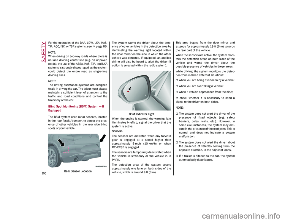
The BSM system uses radar sensors, located
in the rear fascia/bumper, to detect the pres -
ence of other vehicles in the rear side blind
spots of your vehicle.
Rear Sensor Location The system warns the driver about the pres
-
ence of other vehicles in the detection area by
illuminating the warning light located within
the door mirror on the side in which the other
vehicle was detected. If equipped, an audible
chime will also be heard to alert the driver (if
option is selected within the radio system).
BSM Indicator Light
When the engine is started, the warning light
illuminates briefly to signal the driver that the
system is active.
Sensors
The sensors are activated when any forward
gear is engaged at a speed higher than
approximately 6 mph (10 km/h) or when
REVERSE is engaged.
The sensors are temporarily deactivated when
the vehicle is stationary or the vehicle is in
PARK.
The detection area of the system covers
approximately one lane on both sides of the
vehicle, which is around 9 ft (3 m). This area begins from the door mirror and
extends for approximately 19 ft (6 m) towards
the rear part of the vehicle.
When the sensors are active, the system moni
-
tors the detection areas on both sides of the
vehicle and warns the driver about the
possible presence of vehicles in these areas.
While driving, the system monitors the detec -
tion zone in three different situations:
when you are being overtaken by a vehicle;
when you are overtaking a vehicle;
when a vehicle approaches from the side;
to check whether it is necessary to send a
signal to the driver on both sides.
NOTE:
The system does not alert the driver of the
presence of fixed objects (e.g. safety
barriers, poles, walls, etc.). However, in
some circumstances, the system may acti -
vate in the presence of these objects. This is
normal and does not indicate a system
malfunction.
The system does not alert the driver about
the presence of vehicles coming from the
opposite direction, in the adjacent lanes.
If a trailer is hitched to the car, the system
automatically deactivates.
21_GU_OM_EN_USC_t.book Page 150
Page 171 of 280
169
Supplemental Restraint Systems (SRS)
Some of the safety features described in this
section may be standard equipment on some
models, or may be optional equipment on
others. If you are not sure, ask an authorized
dealer.
The air bag system must be ready to protect
you in a collision. The Occupant Restraint
Controller (ORC) monitors the internal circuits
and interconnecting wiring associated with the
electrical Air Bag System Components. Your
vehicle may be equipped with the following Air
Bag System Components:
Air Bag System Components
Occupant Restraint Controller (ORC)
Air Bag Warning Light
Steering Wheel and Column
Instrument Panel
Knee Impact Bolsters
Driver and Front Passenger Air Bags
Seat Belt Buckle Switch
Supplemental Side Air Bags
Supplemental Knee Air Bags
Front and Side Impact Sensors
Seat Belt Pretensioners
Seat Track Position Sensors
Air Bag Warning Light
The Occupant Restraint Controller
(ORC) monitors the readiness of the
electronic parts of the air bag system
whenever the ignition switch is in the
START or ON/RUN position. If the ignition
switch is in the OFF position or in the ACC posi -
tion, the air bag system is not on and the air
bags will not inflate.
The ORC contains a backup power supply
system that may deploy the air bag system
even if the battery loses power or it becomes
disconnected prior to deployment.
The ORC turns on the Air Bag Warning Light in
the instrument panel for approximately four to
eight seconds for a self-check when the igni -
tion switch is first in the ON/RUN position.
After the self-check, the Air Bag Warning Light
will turn off. If the ORC detects a malfunction
in any part of the system, it turns on the Air
Bag Warning Light, either momentarily or continuously. A single chime will sound to alert
you if the light comes on again after initial
startup.
The ORC also includes diagnostics that will illu
-
minate the instrument panel Air Bag Warning
Light if a malfunction is detected that could
affect the air bag system. The diagnostics also
record the nature of the malfunction. While
the air bag system is designed to be mainte -
nance free, if any of the following occurs, have
an authorized dealer service the air bag
system immediately.The Air Bag Warning Light does not come on
during the four to eight seconds when the
ignition switch is first in the ON/RUN posi -
tion.
The Air Bag Warning Light remains on after
the four to eight-second interval.
The Air Bag Warning Light comes on inter-
mittently or remains on while driving.
NOTE:
If the speedometer, tachometer, or any engine
related gauges are not working, the Occupant
Restraint Controller (ORC) may also be
disabled. In this condition the air bags may not
be ready to inflate for your protection. Have an
authorized dealer service the air bag system
immediately.
Do not use the Automatic Locking Mode to
restrain occupants who are wearing the
seat belt or children who are using booster
seats. The locked mode is only used to
install rear-facing or forward-facing child
restraints that have a harness for
restraining the child.
WARNING! (Continued)
21_GU_OM_EN_USC_t.book Page 169
Page 178 of 280
SAFETY
176
NOTE:
After an accident, remember to cycle the igni-
tion to the OFF position and remove the key
from the ignition switch to avoid draining the
battery. Carefully check the vehicle for fuel
leaks in the engine compartment and on the
ground near the engine compartment and fuel
tank before resetting the system and starting
the engine. If there are no fuel leaks or
damage to the vehicle electrical devices (e.g.
headlights) after an accident, reset the system by following the procedure described below. If
you have any doubt, contact an authorized
dealer.
Enhanced Accident Response System
Reset Procedure
After the event occurs, when the system is
active, a message regarding fuel cutoff is
displayed. Turn the ignition switch from igni
-
tion ACC or ON/RUN to ignition OFF. Carefully
check the vehicle for fuel leaks in the engine compartment and on the ground near the
engine compartment and fuel tank before
resetting the system and starting the engine.
Depending on the nature of the event the left
and right turn signal lights, located in the
instrument panel, may both be blinking and
will continue to blink. In order to move your
vehicle to the side of the road, you must follow
the system reset procedure.
Customer Action
NOTE:
Each step MUST BE held for at least two secondsCustomer Will See
1. Turn ignition OFF. (Turn Signal Switch Must be placed in
Neutral State).
2. Turn ignition ACC. Right turn light BLINKS.
Left turn light is OFF.
3. Turn right turn signal switch ON. Right turn light is ON SOLID.
Left turn light BLINKS.
4. Place turn signal in neutral state. Right turn light is OFF.
Left turn light BLINKS.
5. Turn left turn signal switch ON. Right turn light BLINKS.
Left turn light is ON SOLID.
6. Place turn signal in neutral state. Right turn light BLINKS.
Left turn light is OFF.
7. Turn right turn signal switch ON. Right turn light is ON SOLID.
Left turn light BLINKS.
8. Place turn signal in neutral state. Right turn light is OFF.
Left turn light BLINKS.
21_GU_OM_EN_USC_t.book Page 176
Page 192 of 280
SAFETY
190
(Continued)
(Continued)
Periodic Safety Checks You Should Make
Outside The Vehicle
Tires
Examine tires for excessive tread wear and
uneven wear patterns. Check for stones, nails,
glass, or other objects lodged in the tread or
sidewall. Inspect the tread for cuts and cracks.
Inspect sidewalls for cuts, cracks, and bulges.
Check the wheel nuts for tightness. Check the
tires (including spare) for proper cold inflation
pressure.
Lights
Have someone observe the operation of brake
lights and exterior lights while you work the controls. Check turn signal and high beam
indicator lights on the instrument panel.
Door Latches
Check for proper closing, latching, and locking.
Fluid Leaks
Check area under the vehicle after overnight
parking for fuel, coolant, oil, or other fluid
leaks. Also, if gasoline fumes are detected or if
fuel, or brake fluid leaks are suspected, the
cause should be located and corrected imme
-
diately.
Exhaust Gas
ONLY use the driver’s side floor mat on the
driver’s side floor area. To check for inter -
ference, with the vehicle properly parked
with the engine off, fully depress the
accelerator, the brake, and the clutch
pedal (if present) to check for interfer -
ence. If your floor mat interferes with the
operation of any pedal, or is not secure to
the floor, remove the floor mat from the
vehicle and place the floor mat in your
trunk.
ONLY use the passenger’s side floor mat
on the passenger’s side floor area.
ALWAYS make sure objects cannot fall or
slide into the driver’s side floor area when
the vehicle is moving. Objects can become
trapped under accelerator, brake, or
clutch pedals and could cause a loss of
vehicle control.
NEVER place any objects under the floor
mat (e.g., towels, keys, etc.). These
objects could change the position of the
floor mat and may cause interference with
the accelerator, brake, or clutch pedals.
WARNING! (Continued)
If the vehicle carpet has been removed
and re-installed, always properly attach
carpet to the floor and check the floor mat
fasteners are secure to the vehicle carpet.
Fully depress each pedal to check for
interference with the accelerator, brake,
or clutch pedals then re-install the floor
mats.
It is recommended to only use mild soap
and water to clean your floor mats. After
cleaning, always check your floor mat has
been properly installed and is secured to
your vehicle using the floor mat fasteners
by lightly pulling mat.
WARNING! (Continued)
WARNING!
Exhaust gases can injure or kill. They
contain carbon monoxide (CO), which is
colorless and odorless. Breathing it can
make you unconscious and can eventually
poison you. To avoid breathing (CO), follow
these safety tips:
Do not run the engine in a closed garage
or in confined areas any longer than
needed to move your vehicle in or out of
the area.
If you are required to drive with the trunk/lift -
gate/rear doors open, make sure that all
windows are closed and the climate control
BLOWER switch is set at high speed. DO NOT
use the recirculation mode.
21_GU_OM_EN_USC_t.book Page 190
Page 203 of 280
201
11. Apply the adhesive label from the sealantbottle where it can be easily seen by the
driver as a reminder that the tire has been
treated with a Tire Service Kit, as well as
not to exceed the speed restriction for the
treated tire.
NOTE:
Only use original sealant cartridges, which can
be purchased at an authorized dealer.
Checking And Restoring Tire Pressure
The compressor can also be used to check
and, if necessary, restore the tire pressure.
Proceed as follows:
1. Make sure that the power switch is in the
O (off) position.
2. Connect the hose directly to the valve on the tire to be inflated.
3. Insert the plug into the socket in the passenger compartment or in the cargo
area and start the engine.
4. Start the compressor by putting the power switch to I (on). As soon as the correct
pressure is reached, put the power switch
to O (off). Air Compressor And Components
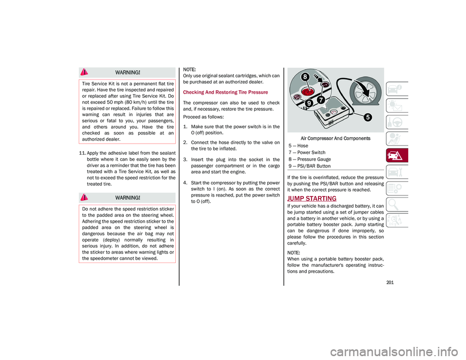
If the tire is overinflated, reduce the pressure
by pushing the PSI/BAR button and releasing
it when the correct pressure is reached.
JUMP STARTING
If your vehicle has a discharged battery, it can
be jump started using a set of jumper cables
and a battery in another vehicle, or by using a
portable battery booster pack. Jump starting
can be dangerous if done improperly, so
please follow the procedures in this section
carefully.
NOTE:
When using a portable battery booster pack,
follow the manufacturer's operating instruc -
tions and precautions.
WARNING!
Tire Service Kit is not a permanent flat tire
repair. Have the tire inspected and repaired
or replaced after using Tire Service Kit. Do
not exceed 50 mph (80 km/h) until the tire
is repaired or replaced. Failure to follow this
warning can result in injuries that are
serious or fatal to you, your passengers,
and others around you. Have the tire
checked as soon as possible at an
authorized dealer.
WARNING!
Do not adhere the speed restriction sticker
to the padded area on the steering wheel.
Adhering the speed restriction sticker to the
padded area on the steering wheel is
dangerous because the air bag may not
operate (deploy) normally resulting in
serious injury. In addition, do not adhere
the sticker to areas where warning lights or
the speedometer cannot be viewed.
5 — Hose
7 — Power Switch
8 — Pressure Gauge
9 — PSI/BAR Button
21_GU_OM_EN_USC_t.book Page 201
Page 210 of 280
208
SERVICING AND MAINTENANCE
Correct servicing permits the performance of
the vehicle to be maintained over time, as well
as limited running costs and safeguarding the
efficiency of the safety systems.
SCHEDULED SERVICING
Correct servicing is crucial for guaranteeing a
long life for the vehicle under the best condi-
tions.
For this reason, Alfa Romeo has planned a
series of checks and services for your vehicle
at fixed intervals based on distance and time,
as described in the Scheduled Servicing Plan.
Before each service, it is always necessary to
carefully follow the instructions in the Sched -
uled Servicing Plan (e.g. periodically check
level of fluids, tire pressure, etc.).
Scheduled Servicing is offered by an autho -
rized dealer according to a set time schedule.
If, during each operation, in addition to the
ones scheduled, the need arises for further
replacements or repairs, these may be carried
out with the owner’s explicit consent only.
NOTE:
Scheduled Servicing intervals are required by
the manufacturer. Failure to have them
carried out may invalidate the New Vehicle
Limited Warranty.
You are advised to inform an authorized
dealer of any small operating irregularities
without waiting for the next service.
Periodic Checks
Every month or every 620 miles (1,000 km) or
before long trips check and, if necessary, top
off:
Engine coolant level.
Brake fluid level (if insufficient, see an
authorized dealer as soon as possible).
Windshield washer fluid level.
Tire inflation pressure and condition.
Operation of lighting system (headlights,
direction indicators, hazard warning lights,
etc.).
Operation of windshield washing/wiping
system and positioning/wear of wiper
blades.
Inspect the CV/Universal joints.
Oil consumption of the engine depends on
conditions and driving style. For this reason,
the engine oil level must be checked every
1,860 miles (3,000 km), and top off if neces -
sary; for further information
Ú
page 215.
Heavy Usage Of The Vehicle
If the vehicle is used under one of the following
conditions:
Dusty roads.
Short, repeated journeys less than 4 miles
(7 km) at sub-zero outside temperatures.
Engine often idling or driving long distances
at low speeds or long periods of inactivity.
In the event of a long period of inactivity.
The following checks must be carried out more
often than indicated in the Scheduled
Servicing Plan:
Check cleanliness of hood and liftgate
locks, cleanliness and lubrication of
linkage.
Visually inspect conditions of: engine, trans -
mission, pipes and hoses (exhaust/fuel
system/brakes) and rubber elements
(sleeves/bushes, etc.).
Check battery charge and battery fluid level
(electrolyte).
Visually inspect conditions of the accessory
drive belts.
Check and, if necessary, change engine oil
and replace oil filter.
Check and, if necessary, replace cabin air
filter.
Check and, if necessary, replace air cleaner.
Severe Duty All Models
Change engine oil at 4,000 miles (6,500 km)
if the vehicle is operated in a dusty and
off-road environment or is operated predomi -
nately at idle or only very low engine RPM. This
type of vehicle use is considered Severe Duty.
21_GU_OM_EN_USC_t.book Page 208
Page 211 of 280
209
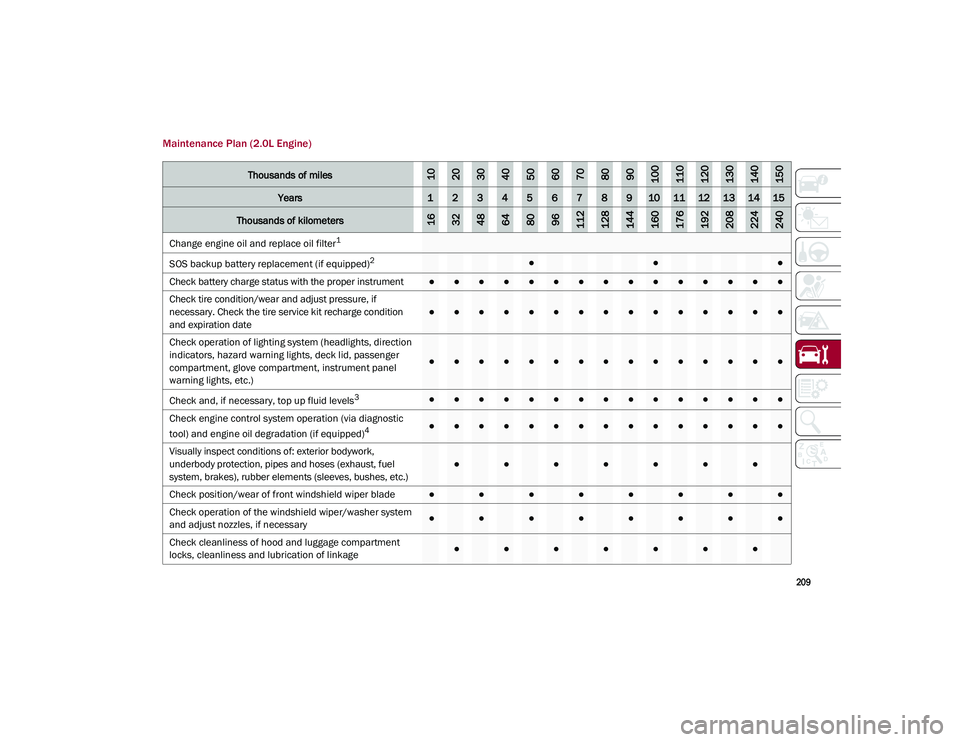
Maintenance Plan (2.0L Engine)
Thousands of miles102030405060708090100110120130140150
Years123456789101112131415
Thousands of kilometers163248648096112128144160176192208224240
Change engine oil and replace oil filter1
SOS backup battery replacement (if equipped)
2●●●
Check battery charge status with the proper instrument
●●●●●●●●●●●●●●●
Check tire condition/wear and adjust pressure, if
necessary. Check the tire service kit recharge condition
and expiration date
●●●●●●●●●●●●●●●
Check operation of lighting system (headlights, direction
indicators, hazard warning lights, deck lid, passenger
compartment, glove compartment, instrument panel
warning lights, etc.)
●●●●●●●●●●●●●●●
Check and, if necessary, top up fluid levels
3●●●●●●●●●●●●●●●
Check engine control system operation (via diagnostic
tool) and engine oil degradation (if equipped)
4●●●●●●●●●●●●●●●
Visually inspect conditions of: exterior bodywork,
underbody protection, pipes and hoses (exhaust, fuel
system, brakes), rubber elements (sleeves, bushes, etc.)
●●●●●●●
Check position/wear of front windshield wiper blade●●●●●●●●
Check operation of the windshield wiper/washer system
and adjust nozzles, if necessary
●●●●●●●●
Check cleanliness of hood and luggage compartment
locks, cleanliness and lubrication of linkage
●●●●●●●
21_GU_OM_EN_USC_t.book Page 209