2021 ALFA ROMEO STELVIO headlights
[x] Cancel search: headlightsPage 48 of 280
GETTING TO KNOW YOUR VEHICLE
46
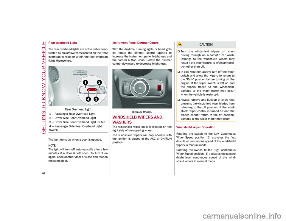
Rear Overhead Light
The rear overhead lights are activated or deac-
tivated by on/off switches located on the front
overhead console or within the rear overhead
lights themselves.
Rear Overhead Light
The light turns on when a door is opened.
NOTE:
The light will turn off automatically after a few
minutes if a door is left open. To turn it on
again, open another door or close and reopen
the same door.
Instrument Panel Dimmer Control
With the daytime running lights or headlights
on, rotate the dimmer control upward to
increase the instrument panel brightness and
the control button icons. Rotate the dimmer
control downward to decrease brightness.
Dimmer Control
WINDSHIELD WIPERS AND
WASHERS
The windshield wiper stalk is located on the
right side of the steering wheel.
The windshield wipers will only operate with
the ignition is placed in the ACC or ON/RUN
position.Windshield Wiper Operation
Rotating the switch to the Low Continuous
Wiper Speed position (2) activates the first
(low) level continuous speed of the windshield
wipers in manual mode.
Rotating the switch to the High Continuous
Wiper Speed position (1) activates the second
(high) level continuous speed of the wind -
shield wipers in manual mode.
1 — Passenger Rear Overhead Light
2 — Driver Side Rear Overhead Light
3 — Driver Side Rear Overhead Light Switch
4 — Passenger Side Rear Overhead Light
Switch
CAUTION!
Turn the windshield wipers off when
driving through an automatic car wash.
Damage to the windshield wipers may
result if the wiper control is left in any posi
-
tion other than off.
In cold weather, always turn off the wiper
switch and allow the wipers to return to
the “Park” position before turning off the
engine. If the wiper switch is left on and
the wipers freeze to the windshield,
damage to the wiper motor may occur
when the vehicle is restarted.
Always remove any buildup of snow that
prevents the windshield wiper blades from
returning to the off position. If the wind -
shield wiper control is turned off and the
blades cannot return to the off position,
damage to the wiper motor may occur.
21_GU_OM_EN_USC_t.book Page 46
Page 50 of 280
GETTING TO KNOW YOUR VEHICLE
48
If the windshield washer is used with the rain
sensor activated, the normal washing cycle is
performed, and then the rain sensor resumes
its normal automatic operation.
NOTE:
Keep the glass in the sensor area clean.
Deactivation
To turn off the Rain Sensing Wipers, use the
wiper switch or place the ignition in the OFF
position.
In the event of malfunction of the rain sensor
while it is active, the windshield wiper oper-
ates intermittently at a speed consistent with
the sensitivity setting of the rain sensor,
whether or not there is rain on the glass for as
long as the sensor failure is indicated on the
display.
The sensor continues to operate and it is
possible to set the windshield wiper to contin -
uous mode (1 or 2). The failure indication
remains on for as long as the sensor is active. The rain sensor is able to recognize and auto
-
matically adjust itself in the presence of the
following conditions:
Presence of dirt on the controlled surface
(e.g. salt, dirt, etc.).
Presence of streaks of water caused by the
worn window wiper blades.
Difference between day and night.
Rear Window Wiper/Washer
Push the windshield wiper lever downward to
activate/deactivate continuous rear wiper
operation.
Push the windshield wiper lever towards the
instrument panel to activate the rear window
washer (a brief push activates one washing
cycle, keeping the stalk pushed washes
continuously until the stalk is released).
Shifting the vehicle into REVERSE with the
windshield wiper operating activates a single
cycle of the rear window wiper.
Headlamp Washers — If Equipped
The windshield wiper lever operates the head -
light washers when the ignition is in the ON
position and the headlights are turned on. To
use the headlight washers, pull the lever
toward you and release it. The headlight
washers will spray a timed high-pressure spray
of washer fluid onto each headlight lens. In
addition, the windshield washers will spray the
windshield and the windshield wipers will
cycle.
NOTE:
The headlight washers work on every tenth
wash cycle request.
CLIMATE CONTROLS
The Climate Control system allows you to regu -
late the temperature, air flow, and direction of
air circulating throughout the vehicle. The
controls are located on the touchscreen and
on the instrument panel below the radio.
21_GU_OM_EN_USC_t.book Page 48
Page 80 of 280
GETTING TO KNOW YOUR INSTRUMENT PANEL
78
Green Indicator Lights
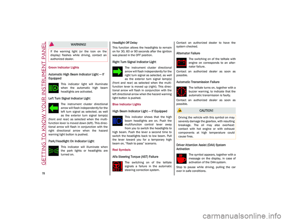
Automatic High Beam Indicator Light — If
Equipped
This indicator light will illuminate
when the automatic high beam
headlights are activated.
Left Turn Signal Indicator Light
The instrument cluster directional
arrow will flash independently for the
left turn signal as selected, as well
as the exterior turn signal lamp(s)
(front and rear) as selected when the multi -
function lever is moved down (left). This direc -
tional arrow will flash in conjunction with the
right directional arrow when the hazard
warning light button is pushed.
Park/Headlight On Indicator Light
This indicator will illuminate when
the park lights or headlights are
turned on. Headlight Off Delay
This function allows the headlights to remain
on for 30, 60 or 90 seconds after the ignition
was placed in the OFF position.
Right Turn Signal Indicator Light
The instrument cluster directional
arrow will flash independently for the
right turn signal as selected, as well
as the exterior turn signal lamp(s)
(front and rear) as selected when the multi -
function lever is moved up (right). This direc -
tional arrow will flash in conjunction with the
left directional arrow when the hazard warning
light button is pushed.
Blue Indicator Lights
High Beam Indicator Light — If Equipped
This indicator shows that the high
beam headlights are on. Push the
multifunction control lever away
from you to switch the headlights to
high beam. Push the lever a second time to
switch the headlights back to low beam. Pull
the lever toward you for a temporary high
beam on, “flash to pass” scenario.
Red Symbols
Alfa Steering Torque (AST) Failure
The switching on of the telltale
signals a failure in the automatic
steering correction system. Contact an authorized dealer to have the
system checked.
Alternator Failure
The switching on of the telltale with
engine on corresponds to an alter
-
nator failure.
Contact an authorized dealer as soon as
possible.
Automatic Transmission Failure
The telltale turns on, together with a
buzzer warning, to indicate that the
automatic transmission is faulty.
Contact an authorized dealer as soon as
possible.
Driver Attention Assist (DAA) System
Activation
The symbol appears, together with a
message on the display, in case of
activation of the DAA system.
Stop to pause while driving, pulling the car
over in safe conditions.
WARNING!
If the warning light (or the icon on the
display) flashes while driving, contact an
authorized dealer.
CAUTION!
Driving the vehicle with this symbol on may
severely damage the gearbox, with resulting
breakage. The oil may also overheat:
contact with hot engine or with exhaust
components at high temperature could
cause fires.
21_GU_OM_EN_USC_t.book Page 78
Page 83 of 280
81
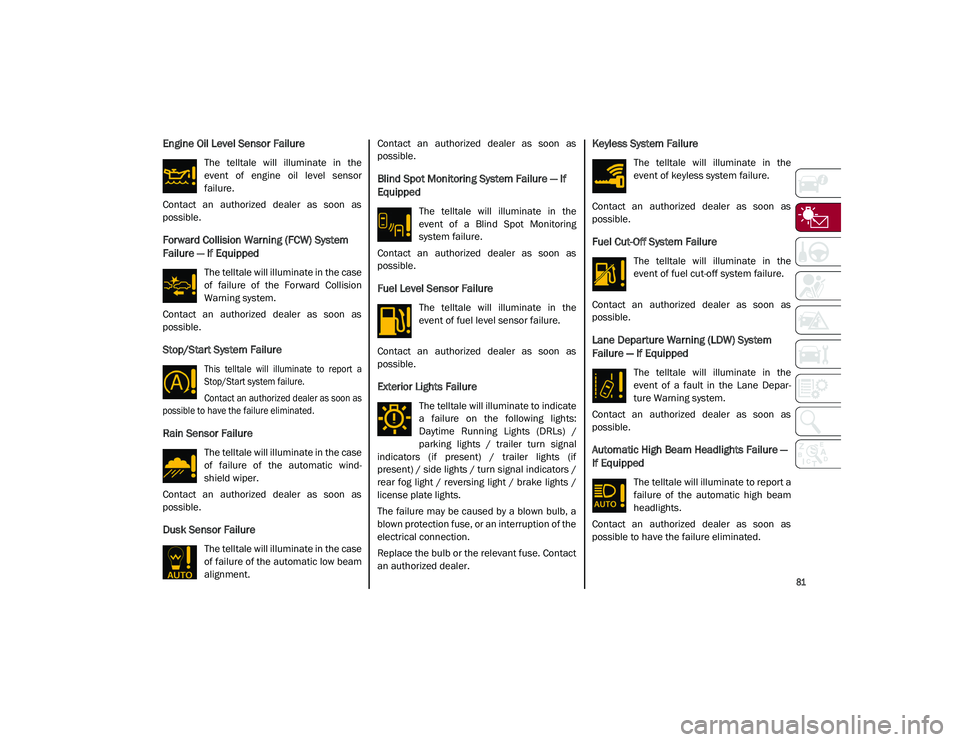
Engine Oil Level Sensor Failure
The telltale will illuminate in the
event of engine oil level sensor
failure.
Contact an authorized dealer as soon as
possible.
Forward Collision Warning (FCW) System
Failure — If Equipped
The telltale will illuminate in the case
of failure of the Forward Collision
Warning system.
Contact an authorized dealer as soon as
possible.
Stop/Start System Failure
This telltale will illuminate to report a
Stop/Start system failure.
Contact an authorized dealer as soon as
possible to have the failure eliminated.
Rain Sensor Failure
The telltale will illuminate in the case
of failure of the automatic wind -
shield wiper.
Contact an authorized dealer as soon as
possible.
Dusk Sensor Failure
The telltale will illuminate in the case
of failure of the automatic low beam
alignment. Contact an authorized dealer as soon as
possible.
Blind Spot Monitoring System Failure — If
Equipped
The telltale will illuminate in the
event of a Blind Spot Monitoring
system failure.
Contact an authorized dealer as soon as
possible.
Fuel Level Sensor Failure
The telltale will illuminate in the
event of fuel level sensor failure.
Contact an authorized dealer as soon as
possible.
Exterior Lights Failure
The telltale will illuminate to indicate
a failure on the following lights:
Daytime Running Lights (DRLs) /
parking lights / trailer turn signal
indicators (if present) / trailer lights (if
present) / side lights / turn signal indicators /
rear fog light / reversing light / brake lights /
license plate lights.
The failure may be caused by a blown bulb, a
blown protection fuse, or an interruption of the
electrical connection.
Replace the bulb or the relevant fuse. Contact
an authorized dealer.
Keyless System Failure
The telltale will illuminate in the
event of keyless system failure.
Contact an authorized dealer as soon as
possible.
Fuel Cut-Off System Failure
The telltale will illuminate in the
event of fuel cut-off system failure.
Contact an authorized dealer as soon as
possible.
Lane Departure Warning (LDW) System
Failure — If Equipped
The telltale will illuminate in the
event of a fault in the Lane Depar -
ture Warning system.
Contact an authorized dealer as soon as
possible.
Automatic High Beam Headlights Failure —
If Equipped
The telltale will illuminate to report a
failure of the automatic high beam
headlights.
Contact an authorized dealer as soon as
possible to have the failure eliminated.
21_GU_OM_EN_USC_t.book Page 81
Page 86 of 280

GETTING TO KNOW YOUR INSTRUMENT PANEL
84
Green Symbols
Headlights
The telltale will illuminate when the
headlights are turned on.
Automatic Headlights
The symbol lights up when the auto-
matic headlights are on.
Stop/Start Operation
The telltale will illuminate in the case
of Stop/Start system intervention
(stopping the engine).
When the engine is restarted, the telltale will
shut off
Ú
page 101.
Cruise Control Activated
The telltale will illuminate when the
Cruise Control system is activated.
Adaptive Cruise Control System — If
Equipped
The symbol comes on when the
Adaptive Cruise Control system is
activated.
Blue Symbols
Automatic High Beam Headlights — If
Equipped
The telltale will illuminate when the
automatic high beam headlights are
activated.
High Beam Headlights
The telltale will illuminate when the
high beam headlights are activated.
ONBOARD DIAGNOSTIC
SYSTEM
Operation
The Onboard Diagnostic system (OBD) carries
out a continuous diagnosis of the components
of the vehicle related to emissions.
It also alerts the driver of when these compo -
nents are no longer in peak condition by
switching on the Engine Check/Malfunc -
tion Indicator warning light on the instrument
panel. The aim of the OBD system (Onboard Diag
-
nostic) is to:
Monitor the efficiency of the system
Indicate an increase in emissions
Indicate the need to replace damaged
components
The vehicle also has a connector, which can
interface with appropriate tools, that makes it
possible to read the error codes stored in the
electronic control units together with a series
of specific parameters for engine operation
and diagnosis. This check can be carried out
by an authorized dealer.
NOTE:
After eliminating a fault, to check the system
completely, an authorized dealer is obliged to
run tests and, if necessary certain road tests.
Onboard Diagnostic System (OBD II)
Cybersecurity
Your vehicle is required to have OBD II and a
connection port to allow access to information
related to the performance of your emissions
controls. Authorized service technicians may
need to access this information to assist with
the diagnosis and service of your vehicle and
emissions system.
21_GU_OM_EN_USC_t.book Page 84
Page 121 of 280
119
System Status
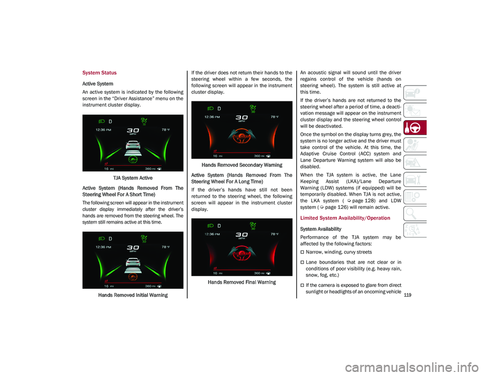
Active System
An active system is indicated by the following
screen in the “Driver Assistance” menu on the
instrument cluster display.TJA System Active
Active System (Hands Removed From The
Steering Wheel For A Short Time)
The following screen will appear in the instrument
cluster display immediately after the driver’s
hands are removed from the steering wheel. The
system still remains active at this time.
Hands Removed Initial Warning If the driver does not return their hands to the
steering wheel within a few seconds, the
following screen will appear in the instrument
cluster display.
Hands Removed Secondary Warning
Active System (Hands Removed From The
Steering Wheel For A Long Time)
If the driver’s hands have still not been
returned to the steering wheel, the following
screen will appear in the instrument cluster
display.
Hands Removed Final Warning An acoustic signal will sound until the driver
regains control of the vehicle (hands on
steering wheel). The system is still active at
this time.
If the driver’s hands are not returned to the
steering wheel after a period of time, a deacti
-
vation message will appear on the instrument
cluster display and the steering wheel control
will be deactivated.
Once the symbol on the display turns grey, the
system is no longer active and the driver must
take control of the vehicle. At this time, the
Adaptive Cruise Control (ACC) system and
Lane Departure Warning system will also be
disabled.
When the TJA system is active, the Lane
Keeping Assist (LKA)/Lane Departure
Warning (LDW) systems (if equipped) will be
temporarily disabled. When TJA is not active,
the LKA system (
Ú
page 128) and LDW
system (
Ú
page 126) will remain active.
Limited System Availability/Operation
System Availability
Performance of the TJA system may be
affected by the following factors:
Narrow, winding, curvy streets
Lane boundaries that are not clear or in
conditions of poor visibility (e.g. heavy rain,
snow, fog, etc.)
If the camera is exposed to glare from direct
sunlight or headlights of an oncoming vehicle
21_GU_OM_EN_USC_t.book Page 119
Page 144 of 280
STARTING AND OPERATING
142
Removing The Receiver
When the receiver is no longer needed, discon-
nect the electrical connections and remove it
from its position using the directions below:
1. Remove the safety split ring from the locking pin.
2. Pull the locking pin out of the trailer hitch.
3. Remove the receiver from the trailer hitch.
SUGGESTIONS FOR DRIVING
Saving Fuel
Below are some suggestions which may help
you save fuel and lower the amount of harmful
emissions released into the atmosphere.
Vehicle Maintenance
Checks and operations should be carried out
in accordance with the Maintenance Plan
Ú
page 208.
Tires
Check the tire pressures at least once every
four weeks: if the pressure is too low,
consumption levels increase as resistance to
rolling is higher.
NOTE:
Tire pressure that is too high can cause
premature tire wear, reduced control, etc. Unnecessary Loads
Do not travel with an overloaded liftgate. The
weight of the vehicle and its arrangement
greatly affect fuel consumption and stability.
Electric Devices
Use electrical systems only for the amount of
time needed. The rear window defroster, addi
-
tional headlights, windshield wipers and
heater blower fan require a considerable
amount of energy; increasing the current
uptake increases fuel consumption (by up to
+25% when city driving).
Climate Control System
Using the climate control system will increase
consumption: use standard ventilation when
the temperature outside permits.
Devices For Aerodynamic Control
The use of non-certified devices for aerody -
namic control may adversely affect air drag
and consumption levels.
Driving Style
Starting
Do not warm up the engine at low or high revs
when the vehicle is stationary; this causes the
engine to warm up more slowly, thereby
increasing fuel consumption and emissions. It
is therefore advisable to drive off immediately,
slowly, avoiding high speeds: by doing this the
engine will warm up more quickly. Unnecessary Actions
Avoid revving up when starting at traffic lights
or before stopping the engine. This action is
unnecessary and causes increased fuel
consumption and pollution.
Gear Selection
Use a high gear when traffic and road condi
-
tions allow it. Using a low gear for faster accel -
eration will increase fuel consumption.
Improper use of a high gear increases
consumption, emissions and engine wear.
Max. Speed
Fuel consumption considerably increases as
speed increases. Maintain a constant speed,
avoiding unnecessary braking and accelera -
tion, which cost in terms of both fuel consump -
tion and emissions.
Acceleration
Accelerating violently severely affects
consumption and emissions: acceleration
should be gradual and should not exceed the
maximum torque.Conditions Of Use
Cold Starting
Short trips and frequent cold starts will not
allow the engine to reach optimum operating
temperature. This results in a significant
increase in consumption levels (from +15 to
+30% in city driving) and emissions.
21_GU_OM_EN_USC_t.book Page 142
Page 178 of 280
SAFETY
176
NOTE:
After an accident, remember to cycle the igni-
tion to the OFF position and remove the key
from the ignition switch to avoid draining the
battery. Carefully check the vehicle for fuel
leaks in the engine compartment and on the
ground near the engine compartment and fuel
tank before resetting the system and starting
the engine. If there are no fuel leaks or
damage to the vehicle electrical devices (e.g.
headlights) after an accident, reset the system by following the procedure described below. If
you have any doubt, contact an authorized
dealer.
Enhanced Accident Response System
Reset Procedure
After the event occurs, when the system is
active, a message regarding fuel cutoff is
displayed. Turn the ignition switch from igni
-
tion ACC or ON/RUN to ignition OFF. Carefully
check the vehicle for fuel leaks in the engine compartment and on the ground near the
engine compartment and fuel tank before
resetting the system and starting the engine.
Depending on the nature of the event the left
and right turn signal lights, located in the
instrument panel, may both be blinking and
will continue to blink. In order to move your
vehicle to the side of the road, you must follow
the system reset procedure.
Customer Action
NOTE:
Each step MUST BE held for at least two secondsCustomer Will See
1. Turn ignition OFF. (Turn Signal Switch Must be placed in
Neutral State).
2. Turn ignition ACC. Right turn light BLINKS.
Left turn light is OFF.
3. Turn right turn signal switch ON. Right turn light is ON SOLID.
Left turn light BLINKS.
4. Place turn signal in neutral state. Right turn light is OFF.
Left turn light BLINKS.
5. Turn left turn signal switch ON. Right turn light BLINKS.
Left turn light is ON SOLID.
6. Place turn signal in neutral state. Right turn light BLINKS.
Left turn light is OFF.
7. Turn right turn signal switch ON. Right turn light is ON SOLID.
Left turn light BLINKS.
8. Place turn signal in neutral state. Right turn light is OFF.
Left turn light BLINKS.
21_GU_OM_EN_USC_t.book Page 176