2021 ALFA ROMEO STELVIO buttons
[x] Cancel search: buttonsPage 43 of 280
41
2. Push the programmed HomeLink® buttonto confirm that the garage door opener
motor operates. If the garage door opener
motor does not operate, repeat the steps
from the beginning.
Programming HomeLink® To A
Miscellaneous Device
Follow the procedure on programming Home -
Link® to a garage door opener
Ú
page 40. Be
sure to determine if the device has a rolling
code, or non-rolling code before beginning the
programming process.
NOTE:
Canadian radio frequency laws require trans -
mitter signals to time-out (or quit) after several
seconds of transmission, which may not be
long enough for HomeLink® to pick up the signal during programming. Similar to this
Canadian law, some U.S. gate operators are
designed to time-out in the same manner. The
procedure may need to be performed multiple
times to successfully pair the device to your
HomeLink® buttons.
Reprogramming A Single HomeLink®
Button
To reprogram a single HomeLink® button that
has been previously trained, without erasing
all the channels, follow the procedure below.
Be sure to determine whether the new device
you want to program the HomeLink® button to
has a Rolling Code, or Non-rolling Code.
1. Place the ignition in the ON/RUN position,
without starting the engine.
2. Push and hold the desired HomeLink® button until the HomeLink® indicator light
begins to flash after 20 seconds. Do not
release the button.
3. Without releasing the button , proceed with
Step 2 in “Programming HomeLink® To A
Garage Door Opener” and follow all
remaining steps.
Canadian/Gate Operator Programming
The programming of transmitters in Canada/
United States require the transmitter signals
to “time-out” after several seconds of trans -
mission. Canadian radio frequency laws require trans
-
mitter signals to time-out (or quit) after several
seconds of transmission – which may not be
long enough for HomeLink® to pick up the
signal during programming. Similar to this
Canadian law, some U.S. gate operators are
designed to time-out in the same manner.
It may be helpful to unplug the device during
the cycling process to prevent possible over -
heating of the garage door or gate motor.
1. Place the ignition in the ON/RUN position.
2. Place the hand-held transmitter 1 to 3 inches (3 to 8 cm) away from the Home -
Link® button you wish to program while
keeping the HomeLink® indicator light in
view.
3. Continue to press and hold the Home -
Link® button, while you press and release
(cycle) your hand-held transmitter every
two seconds until HomeLink® has
successfully accepted the frequency
signal. The indicator light will flash slowly
and then rapidly when fully trained.
4. Watch for the HomeLink® indicator to change flash rates. When it changes, it is
programmed. It may take up to 30 seconds
or longer in rare cases. The garage door
may open and close while you are
programming.
5. Press and hold the programmed Home -
Link® button and observe the indicator
light.
WARNING!
Your motorized door or gate will open and
close while you are programming the
universal transceiver. Do not program the
transceiver if people or pets are in the
path of the door or gate.
Do not run your vehicle in a closed garage or
confined area while programming the transceiver.
Exhaust gas from your vehicle contains Carbon
Monoxide (CO) which is odorless and colorless.
Carbon Monoxide is poisonous when inhaled and
can cause you and others to be severely injured or
killed.
21_GU_OM_EN_USC_t.book Page 41
Page 44 of 280
GETTING TO KNOW YOUR VEHICLE
42
NOTE:
If the indicator light stays on constantly,
programming is complete and the garage
door/device should activate when the
HomeLink® button is pressed.
To program the two remaining HomeLink®
buttons, repeat each step for each
remaining button. DO NOT erase the chan-
nels.
If you unplugged the garage door opener/
device for programming, plug it back in at this
time.
Reprogramming A Single HomeLink® Button
(Canadian/Gate Operator)
To reprogram a channel that has been previ -
ously trained, follow these steps:
1. Place the ignition to the ON/RUN position.
2. Press and hold the desired HomeLink® button until the indicator light begins to
flash after 20 seconds. Do not release the
button.
3. Without releasing the button, proceed with “Canadian/Gate Operator Programming”
step 2 and follow all remaining steps.
EXTERIOR LIGHTS
Headlight Switch
The headlight switch is located on the left side
of the instrument panel, next to the steering wheel. The headlight switch controls the oper
-
ation of the headlights, parking lights, instru -
ment panel lights, instrument panel light
dimming, interior lights and rear fog lights.
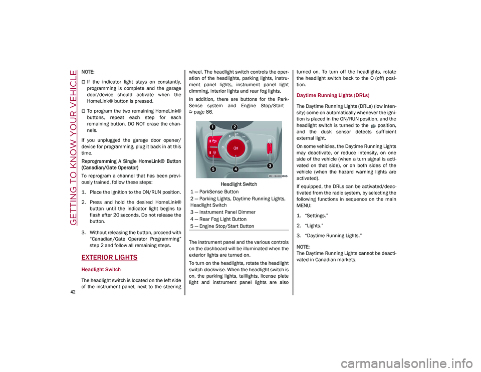
In addition, there are buttons for the Park -
Sense system and Engine Stop/Start
Ú
page 86.
Headlight Switch
The instrument panel and the various controls
on the dashboard will be illuminated when the
exterior lights are turned on.
To turn on the headlights, rotate the headlight
switch clockwise. When the headlight switch is
on, the parking lights, taillights, license plate
light and instrument panel lights are also turned on. To turn off the headlights, rotate
the headlight switch back to the O (off) posi
-
tion.
Daytime Running Lights (DRLs)
The Daytime Running Lights (DRLs) (low inten -
sity) come on automatically whenever the igni -
tion is placed in the ON/RUN position, and the
headlight switch is turned to the position,
and the dusk sensor detects sufficient
external light.
On some vehicles, the Daytime Running Lights
may deactivate, or reduce intensity, on one
side of the vehicle (when a turn signal is acti -
vated on that side), or on both sides of the
vehicle (when the hazard warning lights are
activated).
If equipped, the DRLs can be activated/deac -
tivated from the radio system, by selecting the
following functions in sequence on the main
MENU:
1. “Settings.”
2. “Lights.”
3. “Daytime Running Lights.”
NOTE:
The Daytime Running Lights cannot be deacti -
vated in Canadian markets.
1 — ParkSense Button
2 — Parking Lights, Daytime Running Lights,
Headlight Switch
3 — Instrument Panel Dimmer
4 — Rear Fog Light Button
5 — Engine Stop/Start Button
21_GU_OM_EN_USC_t.book Page 42
Page 52 of 280
GETTING TO KNOW YOUR VEHICLE
50
Automatic Climate Control System (Touchscreen Controls)
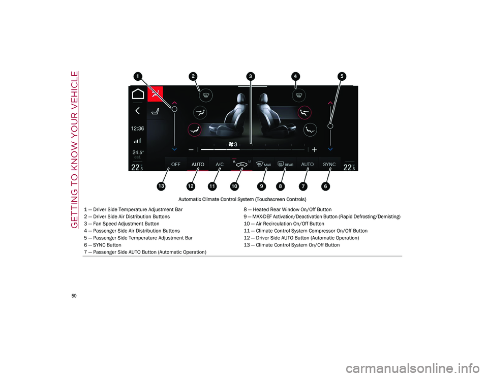
1 — Driver Side Temperature Adjustment Bar 8 — Heated Rear Window On/Off Button
2 — Driver Side Air Distribution Buttons 9 — MAX-DEF Activation/Deactivation Button (Rapid Defrosting/Demisting)
3 — Fan Speed Adjustment Button 10 — Air Recirculation On/Off Button
4 — Passenger Side Air Distribution Buttons 11 — Climate Control System Compressor On/Off Button
5 — Passenger Side Temperature Adjustment Bar 12 — Driver Side AUTO Button (Automatic Operation)
6 — SYNC Button 13 — Climate Control System On/Off Button
7 — Passenger Side AUTO Button (Automatic Operation)
21_GU_OM_EN_USC_t.book Page 50
Page 53 of 280
51
Description
The Automatic Dual Zone Climate Control
System adjusts the temperature and air distri-
bution independently between the driver and
passenger.
The system maintains the set temperature
inside the passenger compartment and
compensates for outside temperature change.
NOTE:
The reference temperature is 72°F (22°C) for
optimal comfort management.
The automatic setting will adjust the following
to maintain comfort within the passenger
compartment:
Air temperature from the driver/front
passenger side vents
Air distribution from the driver/front
passenger side vents
Fan speed (continuous variation of the air
flow)
Compressor variations (for cooling/dehu -
midifying the air)
Air recirculation
The Climate Control System can also be oper -
ated manually by using the buttons and knobs
on the faceplate.
Manual selections will override the automatic
settings, which are stored until the AUTO
button is pushed. If the system intervenes for
safety reasons, the automatic setting will take
control of the system.
The below operations will not deactivate the
automatic (AUTO) function:
Air Recirculation activation/deactivation
A/C activation/deactivation
SYNC function activation
Rear Window Defrost activation/deactiva -
tion
When in AUTO mode, the vehicle’s internal
temperature is controlled according to the set
temperature.
The following can be manually set or adjusted:
Driver/passenger air temperature
Blower speed (continuous variation)
Air distribution (seven positions for driver
and passenger)
A/C activation
Front Defroster
Air recirculation
Rear Defroster
System deactivation
A/C Compressor
Push the A/C button or the icon to activate or
deactivate the A/C compressor (indicator illu-
minated when activated). The A/C compressor
will remain off even after the engine has
stopped.
When the A/C compressor is turned off, the
system deactivates air recirculation to prevent
the windows from fogging up. If the climate
control system can maintain the temperature,
with the A/C turned off, the AUTO feature will
remain on and the AUTO button indicator light
will not switch off.
To restore automatic control of the A/C
compressor, push the A/C button or the icon or
the AUTO button. With the A/C compressor off,
the air speed can be set manually using the Air
Speed Adjustment Knob.
When the A/C compressor is on, and the
engine is running, air speed cannot be lower
than the minimum speed (only one indicator
light is lit).
CAUTION!
The system uses R1234yf refrigerant,
which does not pollute the environment in
the event of accidental leakage. Under no
circumstances, use R134a and R12 fluids,
which are incompatible with the
components of this system.
21_GU_OM_EN_USC_t.book Page 51
Page 56 of 280
GETTING TO KNOW YOUR VEHICLE
54
the flow of air. The air vanes of the center
outlets and outboard outlets can be moved up
and down or side to side to regulate airflow
direction. There is a shut off wheel located
below the air vanes to shut off or adjust the
amount of airflow from these outlets.
Bi-Level Mode
Air comes from the instrument panel
outlets and floor outlets. A slight
amount of air is directed through the
defrost and side window demister
outlets.
NOTE:
Bi-Level mode is designed under comfort
conditions to provide cooler air out of the
panel outlets and warmer air from the floor
outlets.
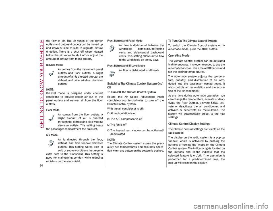
Floor Mode
Air comes from the floor outlets. A
slight amount of air is directed
through the defrost and side window
demister outlets. This setting heats
the passenger compartment the quickest.
Mix Mode
Air is directed through the floor,
defrost, and side window demister
outlets. This setting works best in
cold or snowy conditions that require
extra heat to the windshield. This setting is
good for maintaining comfort while reducing
moisture on the windshield.
Front Defrost And Panel Mode
Air flow is distributed between the
windshield demisting/defrosting
vents and side/central dashboard
vents. This setting allows air to flow
to the windshield on sunny days.
Front Defrost And Bi-Level Mode
Air flow is distributed to all vents.
Switching The Climate Control System On/
Off
To Turn Off The Climate Control System
Rotate the Air Speed Adjustment Knob
completely counterclockwise to turn off the
Climate Control system.
With the air conditioner is off:
Air recirculation is on
The A/C compressor is off
The fan is off
The heated rear window can be activated/
deactivated
NOTE:
The Climate Control system stores the previ -
ously set temperatures and resumes opera -
tion when any button on the system is pushed. To Turn On The Climate Control System
To switch the Climate Control system on in
automatic mode, push the AUTO button.
Operating Mode
The Climate Control system can be activated
in different ways. It is recommended to use the
automatic function. Push the AUTO button and
set the desired temperatures.
The automatic system adjusts the tempera
-
ture, quantity, and distribution of air intro -
duced into the passenger compartment. It
also controls air recirculation and the activa -
tion of the air conditioner.
At any time during automatic operation, you
can change the temperature, activate or deac -
tivate the Rear Defrost, activate SYNC, acti -
vate or deactivate the air conditioner, and
activate or deactivate air recirculation. The
system will automatically adjust to the new
settings.
Climate Control Display Settings
The Climate Control settings are visible on the
radio screen.
The display on the radio system is a pop up
window, which is activated by pushing the
buttons or turning the knobs on the Climate
Control system. The indicator lights located on
the buttons and knobs indicate that the
selected feature is on/off. If no operation is
performed for a predetermined time, the
pop-up will close on the display.
21_GU_OM_EN_USC_t.book Page 54
Page 61 of 280
59
To close the window, pull the window switch
up. To stop the window during Auto-Up opera-
tion, push or pull the window switch again.
Auto-Up Feature With Anti-Pinch Protection
The vehicle is equipped with an anti-pinch
safety device for closing the windows.
If the safety system senses any obstacle while
the window is closing, it will stop the window’s
movement and reverse it, depending on its
position.
This device is also useful if the windows are
activated accidentally by children inside the
vehicle.
The anti-pinch safety function is activated both
during the manual and the automatic opera -
tion of the window.
When the anti-pinch system is activated, the
window closing is immediately interrupted.
Then the window closing is automatically reversed and the window lowers by about
8 inches (20 cm) in relation to the first stop
position. The window cannot be operated
during this time.
NOTE:
In the event of an error, or if the anti-pinch
protection is activated three consecutive
times, the automatic closing operation of the
window will be deactivated. In order to restore
the correct operation of the system, the
window must be lowered.
Power Window System Initialization
If power supply is interrupted, the electric
window automatic operation must be reinitial
-
ized.
To perform the initialization procedure, which
must be done on each door with the doors
closed, manually fully close the window to be
initialized.
Wind Buffeting
Wind buffeting can be described as the
perception of pressure on the ears or a heli -
copter-type sound in the ears. Your vehicle
may exhibit wind buffeting with the windows
down, or the sunroof (if equipped) in certain
open or partially open positions. This is a
normal occurrence and can be minimized. If
the buffeting occurs with the rear windows
open, open the front and rear windows together to minimize the buffeting. If the
buffeting occurs with the sunroof open, adjust
the sunroof opening to minimize the buffeting
or open any window.
POWER SUNROOF — IF
EQUIPPED
Power Sunroof
The power sunroof consists of a single glass
panel and is fitted with a power sunshade the
full length of the panel.
Operation of the sunroof is only possible with
the ignition in the ACC or ON/RUN position
Ú
page 20.
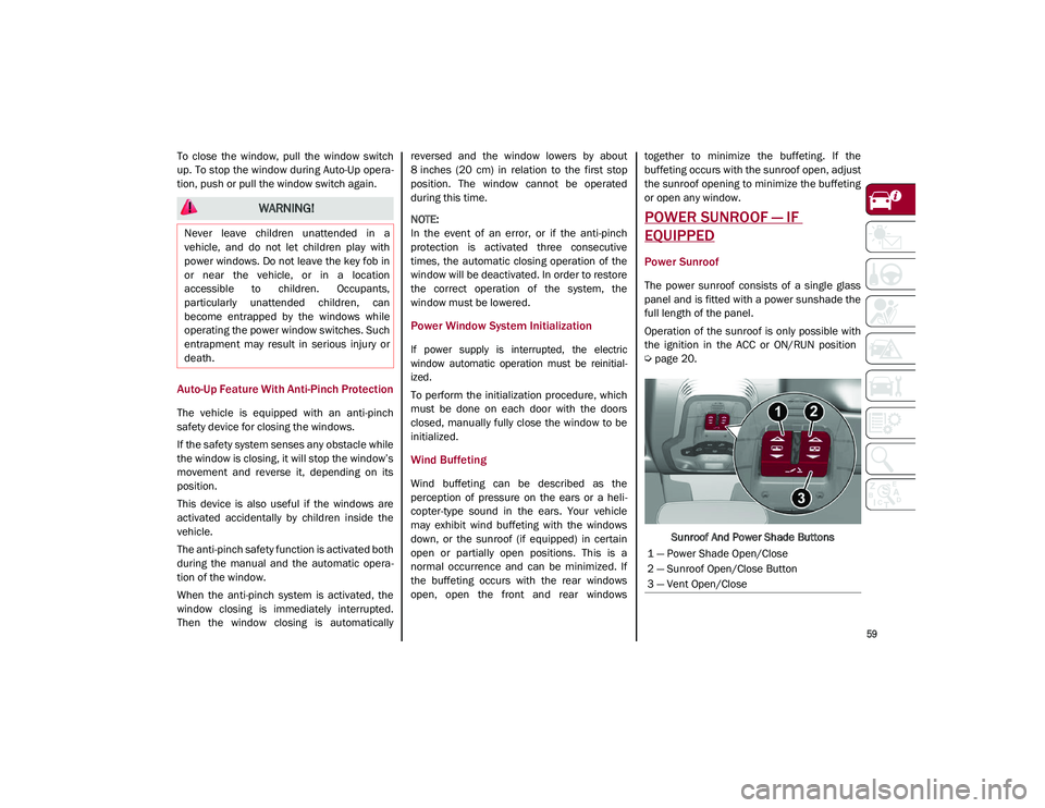
Sunroof And Power Shade Buttons
WARNING!
Never leave children unattended in a
vehicle, and do not let children play with
power windows. Do not leave the key fob in
or near the vehicle, or in a location
accessible to children. Occupants,
particularly unattended children, can
become entrapped by the windows while
operating the power window switches. Such
entrapment may result in serious injury or
death.
1 — Power Shade Open/Close
2 — Sunroof Open/Close Button
3 — Vent Open/Close
21_GU_OM_EN_USC_t.book Page 59
Page 65 of 280
63
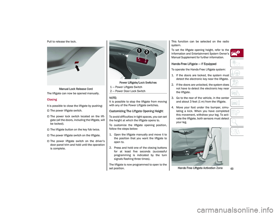
Pull to release the lock.Manual Lock Release Cord
The liftgate can now be opened manually.
Closing
It is possible to close the liftgate by pushing:
The power liftgate switch.
The power lock switch located on the lift -
gate (all the doors, including the liftgate, will
be locked).
The liftgate button on the key fob twice.
The power liftgate switch on the liftgate.
The power liftgate switch on the driver’s
door panel trim and hold until the operation
is complete. Power Liftgate/Lock Switches
NOTE:
It is possible to stop the liftgate from moving
with any of the Power Liftgate switches.
Customizing The Liftgate Opening Height
To avoid difficulties in tight spaces, you can set
the height at which the liftgate opens to.
To customize the liftgate opening position,
follow the steps below:
1. Open the liftgate manually and move it to the position that you want the liftgate to
open to.
2. Press and hold one of the closing buttons for at least five seconds (successful
programming is indicated by the turn
signals flashing three times).
The liftgate is now programmed to open to the
set position. This function can be selected on the radio
system.
To set the liftgate opening height, refer to the
Information and Entertainment System Owner’s
Manual Supplement for further information.
Hands-Free Liftgate — If Equipped
To operate the Hands-Free Liftgate system:
1. If the doors are locked, the system must
detect the electronic key near the liftgate.
2. If the doors are unlocked, the system does not have to detect the electronic key near
the liftgate.
3. Go to the rear of the vehicle, in the center and about 3 feet (1 m) from the liftgate.
4. Move your foot under the bumper, simu -
lating a kick. When you have completed
this movement, withdraw your leg. To acti -
vate the liftgate, both sensors must detect
your leg.
Hands Free Liftgate Activation Zone
1 — Power Liftgate Switch
2 — Power Door Lock Switch
21_GU_OM_EN_USC_t.book Page 63
Page 106 of 280
STARTING AND OPERATING
104
To access the function on the main menu,
select the following items in order:
1. “Driver Assistance”
2. “Speed Limiter - Set Speed”
By turning the Rotary Pad, the speed increases
by 5 mph (5 km/h), from a minimum of
18 mph (30 km/h) to a maximum of 112 mph
(180 km/h).
Exceeding The Programmed Speed
By fully pressing the accelerator pedal, the
programmed speed can be exceeded even
with the device active (e.g. in the event of over-
taking).
The device is disabled until the speed drops
below the set limit, after which it reactivates
automatically.
Programmed Speed Icon Flashing
The programmed speed will flash in the
following scenarios:
When the accelerator pedal has been fully
pressed and the vehicle has exceeded the
programmed speed.
Activating the system after setting a limit
below the effective speed of the vehicle.
In the event of overtake acceleration.
Deactivation
The feature can be activated/deactivated
through the radio system.
Deactivating The Device
To access this feature, select the “Driver Assis -
tance” widget in the radio system, then select
the following items in sequence:
1. “Speed Limiter”
2. “OFF”
Automatic Deactivation Of The Device
The device deactivates automatically in the
event of fault in the system. In this case,
contact an authorized dealer.
Temporary Signal Loss
When the devices loses the signal, the white
symbol without the speed indication illumi -
nates on the display.
System Failure
If there is a system failure, the amber symbol
illuminates on the display.
CRUISE CONTROL SYSTEMS — IF
EQUIPPED
Cruise Control — If Equipped
When engaged, the Cruise Control takes over
accelerator operations at speeds greater than
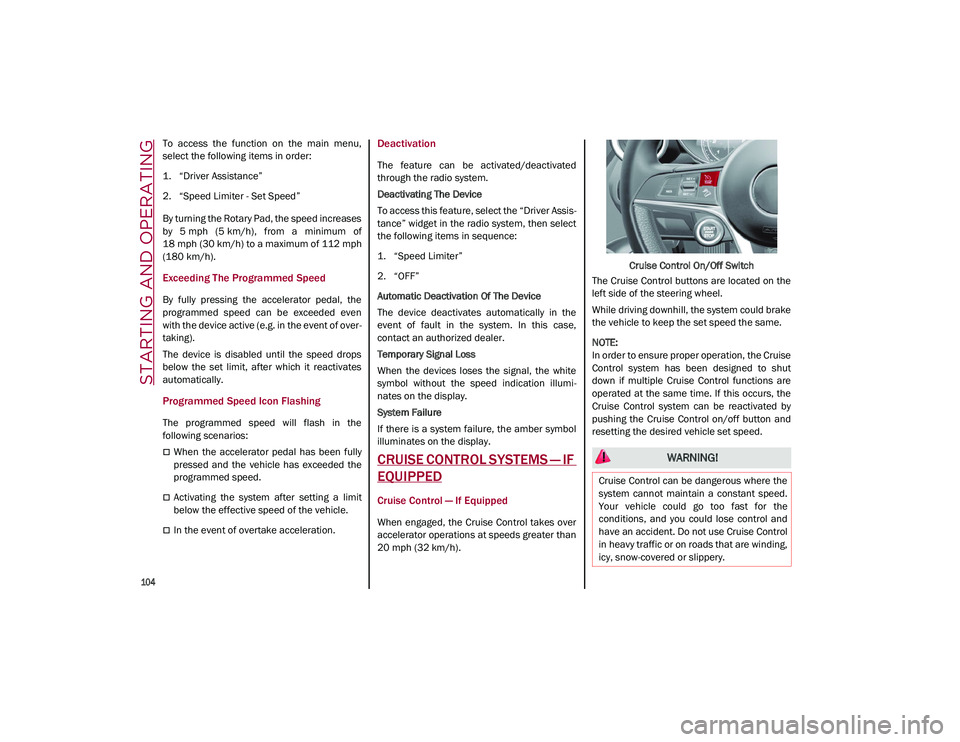
20 mph (32 km/h). Cruise Control On/Off Switch
The Cruise Control buttons are located on the
left side of the steering wheel.
While driving downhill, the system could brake
the vehicle to keep the set speed the same.
NOTE:
In order to ensure proper operation, the Cruise
Control system has been designed to shut
down if multiple Cruise Control functions are
operated at the same time. If this occurs, the
Cruise Control system can be reactivated by
pushing the Cruise Control on/off button and
resetting the desired vehicle set speed.
WARNING!
Cruise Control can be dangerous where the
system cannot maintain a constant speed.
Your vehicle could go too fast for the
conditions, and you could lose control and
have an accident. Do not use Cruise Control
in heavy traffic or on roads that are winding,
icy, snow-covered or slippery.
21_GU_OM_EN_USC_t.book Page 104