2021 ALFA ROMEO STELVIO brake
[x] Cancel search: brakePage 23 of 280
21
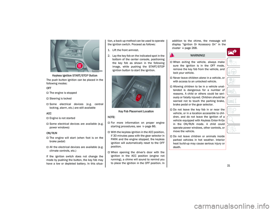
Keyless Ignition START/STOP Button
The push button ignition can be placed in the
following modes:
OFF
The engine is stopped
Steering is locked
Some electrical devices (e.g. central
locking, alarm, etc.) are still available
ACC
Engine is not started
Some electrical devices are available (e.g.
power windows)
ON/RUN
The engine will start (when foot is on the
brake pedal)
All the electrical devices are available (e.g.
climate controls, etc.)
If the ignition switch does not change the
mode by pushing the button, the key fob may
have a low or depleted battery. In this situa -tion, a back up method can be used to operate
the ignition switch. Proceed as follows:
1. Lift the front armrest.
2. Lay the key fob on the indicated spot in the
bottom of the center console, positioning
the key fob as shown in the following
image, while pushing the START/STOP
ignition button to start the ignition.
Key Fob Placement Location
NOTE:
For more information on proper engine
starting procedures, see
Ú
page 86.
With the keyless ignition in the ACC position,
if 30 minutes pass with the gear selector in
PARK and the engine stopped, the keyless
ignition will automatically reset to the OFF
position.
When opening the driver's door with the
ignition in the ACC position (engine not
running), a chime will sound to remind you
to place the ignition in the OFF position. In addition to the chime, the message will
display “Ignition Or Accessory On” in the
cluster
Ú
page 268.
WARNING!
When exiting the vehicle, always make
sure the ignition is in the OFF mode,
remove the key fob from the vehicle, and
lock your vehicle.
Never leave children alone in a vehicle, or
with access to an unlocked vehicle.
Allowing children to be in a vehicle unat -
tended is dangerous for a number of
reasons. A child or others could be seri -
ously or fatally injured. Children should be
warned not to touch the parking brake,
brake pedal or the gear selector.
Do not leave the key fob in or near the
vehicle, or in a location accessible to chil -
dren, and do not leave the ignition of a
vehicle equipped with Keyless Enter-N-Go
in the ON/RUN mode. A child could
operate power windows, other controls, or
move the vehicle.
Do not leave children or animals inside
parked vehicles in hot weather. Interior
heat build-up may cause serious injury or
death.
21_GU_OM_EN_USC_t.book Page 21
Page 24 of 280

GETTING TO KNOW YOUR VEHICLE
22
REMOTE START — IF EQUIPPED
This system uses the key fob to start
the engine conveniently from
outside the vehicle while still main-
taining security.
NOTE:
Obstructions between the vehicle and key fob
may reduce this range
Ú
page 268.
How To Use Remote Start
Push the Remote Start button on the key fob
twice within five seconds. The vehicle doors will lock, the turn signals will flash twice, and
the horn will chirp twice. Pushing the Remote
Start button a third time shuts the engine off.
NOTE:
With Remote Start, the engine will only run
for 15 minutes.
Remote Start can only be used twice.
If an engine fault is present or fuel level is
low, the vehicle will start and then shut
down in 10 seconds.
The park lamps will turn on and remain on
during Remote Start mode.
For security, power window operation is
disabled when the vehicle is in the Remote
Start mode.
The ignition must be placed in the ACC posi
-
tion before the Remote Start sequence can
be repeated for a third cycle.
All of the following conditions must be met
before the engine will Remote Start:
Gear selector in PARK
Doors closed
Hood closed
Liftgate closed
Hazard switch off
Brake switch inactive (brake pedal not
pushed)
Battery at an acceptable charge level
PANIC button not pushed
System not disabled from previous remote
start event
Vehicle Security system indicator flashing
Ignition in OFF position
Fuel level meets minimum requirement
Vehicle Security system is not signaling an
intrusion
Malfunction Indicator Light is not illumi -
nated
To Exit Remote Start Mode
To drive the vehicle after starting the Remote
Start system, either push and release the
unlock button on the key fob to unlock the
doors, or unlock the vehicle using Passive
Entry via the door handles, and disarm the
vehicle security system (if equipped). Then,
prior to the end of the 15 minute cycle, push
and release the START/STOP ignition button
while pressing the brake pedal.
The Remote Start system will turn the engine
off with another push and release of the
Remote Start button on the key fob, or if the
engine is allowed to run for the entire
15 minute cycle.
CAUTION!
An unlocked vehicle is an invitation for
thieves. Always remove key fob from the
vehicle and lock all doors when leaving the
vehicle unattended.
WARNING!
Do not start or run an engine in a closed
garage or confined area. Exhaust gas
contains Carbon Monoxide (CO) which is
odorless and colorless. Carbon Monoxide
is poisonous and can cause serious injury
or death when inhaled.
Keep key fobs away from children. Opera -
tion of the Remote Start system, windows,
door locks or other controls could cause
serious injury or death.
21_GU_OM_EN_USC_t.book Page 22
Page 26 of 280
GETTING TO KNOW YOUR VEHICLE
24
(Continued)
battery is reconnected; the exterior lights will
flash, and the horn will sound. If this occurs,
disarm the Vehicle Security system.
NOTE:
The alarm does not disarm when the doors are
unlocked by inserting the blade of the emer-
gency key (found inside the key fob) into the
door handle lock cylinder.
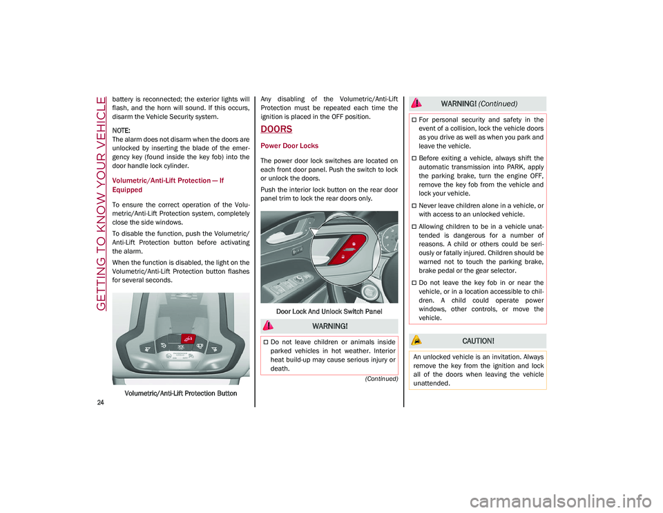
Volumetric/Anti-Lift Protection — If
Equipped
To ensure the correct operation of the Volu -
metric/Anti-Lift Protection system, completely
close the side windows.
To disable the function, push the Volumetric/
Anti-Lift Protection button before activating
the alarm.
When the function is disabled, the light on the
Volumetric/Anti-Lift Protection button flashes
for several seconds.
Volumetric/Anti-Lift Protection Button Any disabling of the Volumetric/Anti-Lift
Protection must be repeated each time the
ignition is placed in the OFF position.
DOORS
Power Door Locks
The power door lock switches are located on
each front door panel. Push the switch to lock
or unlock the doors.
Push the interior lock button on the rear door
panel trim to lock the rear doors only.
Door Lock And Unlock Switch Panel
WARNING!
Do not leave children or animals inside
parked vehicles in hot weather. Interior
heat build-up may cause serious injury or
death.
For personal security and safety in the
event of a collision, lock the vehicle doors
as you drive as well as when you park and
leave the vehicle.
Before exiting a vehicle, always shift the
automatic transmission into PARK, apply
the parking brake, turn the engine OFF,
remove the key fob from the vehicle and
lock your vehicle.
Never leave children alone in a vehicle, or
with access to an unlocked vehicle.
Allowing children to be in a vehicle unat -
tended is dangerous for a number of
reasons. A child or others could be seri -
ously or fatally injured. Children should be
warned not to touch the parking brake,
brake pedal or the gear selector.
Do not leave the key fob in or near the
vehicle, or in a location accessible to chil -
dren. A child could operate power
windows, other controls, or move the
vehicle.
CAUTION!
An unlocked vehicle is an invitation. Always
remove the key from the ignition and lock
all of the doors when leaving the vehicle
unattended.
WARNING! (Continued)
21_GU_OM_EN_USC_t.book Page 24
Page 63 of 280
61
Proceed as follows:
1. With the ignition in the ON/RUN position,make sure the sunroof glass is fully closed
(sunshade open).
2. Open the driver’s side door, and place the ignition in the OFF position.
3. Within five seconds, place the ignition in the ACC or ON/RUN position.
4. Within 10 seconds, push and hold the sunroof close switch (forward). After 8 -
10 seconds of holding the switch, the
re-initialization process will begin.
Continue to hold the switch while the
sunroof motor cycles, and the sunshade
will fully close.
5. Once the sunroof glass and the power sunshade have stopped motion, release
the sunroof close switch, then push and
hold it again within five seconds. Continue
to hold the switch while the sunshade fully
opens, the sunroof glass fully opens,
followed by the glass fully closing then the
sunshade fully closing.
6. Release the switch once all of the opera -
tions stop. Re-initialization of the sunroof
motors is now complete.
NOTE:
If the switch is released prior to full completion
of the operations described, the entire
re-initialization procedure must be repeated
from step 1. 7. Confirm express operations for the
sunroof glass and sunshade are functional
for opening and closing operations.
Sunroof Maintenance
Use only a non-abrasive cleaner and a soft
cloth to clean the glass panel. Periodically
check for and clear out any debris that may
have collected in the tracks.
HOOD
Opening The Hood
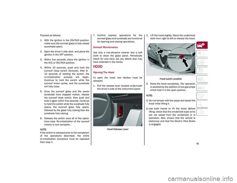
To open the hood, two latches must be
released.
1. Pull the release lever located underneaththe driver’s side of the instrument panel.
Hood Release Lever 2. Lift the hood slightly. Move the underhood
latch from right to left to release the hood.
Hood Latch Location
3. Raise the hood completely. The operation is assisted by the addition of two gas props
which hold it in the open position.
NOTE:
Do not tamper with the props and assist the
hood while lifting it.
Use both hands to lift the hood. Before
lifting, check that the windshield wiper arms
are not raised from the windshield or in
operation. Also, ensure that the vehicle is
stationary and that the Electric Park Brake
is engaged.
21_GU_OM_EN_USC_t.book Page 61
Page 74 of 280
GETTING TO KNOW YOUR INSTRUMENT PANEL
72
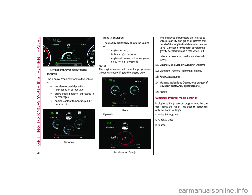
Normal and Advanced Efficiency
Dynamic
The display graphically shows the values
of: ○ accelerator pedal position (expressed in percentage);
○ brake pedal position (expressed in percentage);
○ engine coolant temperature (H = hot C = cold).
Dynamic Race (If Equipped)
The display graphically shows the values
of:
○ engine torque;
○ turbocharger pressure;
○ engine oil pressure (L = low pres -
sure/H= high pressure).
NOTE:
The engine torque and turbocharger pressure
values vary according to the engine type.
Race
Dynamic
Acceleration Gauge The displayed parameters are related to
vehicle stability, the graphs illustrate the
trend of the longitudinal/lateral accelera
-
tions (G-meter information), considering
gravity acceleration as a reference unit.
Lateral acceleration peaks are also indi -
cated.
11. Driving Mode Display (Alfa DNA System)
12. Distance Traveled (miles/km) display
13. Fuel Consumption
14. Warning Indications Display (e.g. danger of ice, open doors, ABS operation, etc.)
15. Range
Customer Programmable Settings
Multiple settings can be programmed by the
user using the radio. This section describes
only the basic settings:
Units & Language
Clock & Date
Cluster
21_GU_OM_EN_USC_t.book Page 72
Page 76 of 280
GETTING TO KNOW YOUR INSTRUMENT PANEL
74
(Continued)
To access and the change the setting, turn and
push the Rotary Pad or press the desired
setting on the touchscreen.
WARNING LIGHTS AND
MESSAGES ON THE
INSTRUMENT PANEL
The following pages consist of warning lights
and messages.
NOTE:
The warning light turns on together with a
dedicated message and/or chime when
applicable. These indications are precau-
tionary and as such must not be considered
as exhaustive and/or alternative to the
information contained in the Owner’s
Manual, which you are advised to read care -
fully in all cases. Always refer to the informa -
tion in this section in the event of a failure
indication.
The failure indicators appearing on the
display are divided into two categories: very
serious and less serious faults. Serious
faults are indicated by a repeated and
prolonged warning cycle. Less serious faults
are indicated by a warning cycle with a
shorter duration. You can stop the warning
cycle in both cases by pushing the button
located on the windshield wiper stalk. The
instrument panel warning light will stay on
until the cause of the failure is eliminated.
Red Warning Lights
Air Bag Warning Light
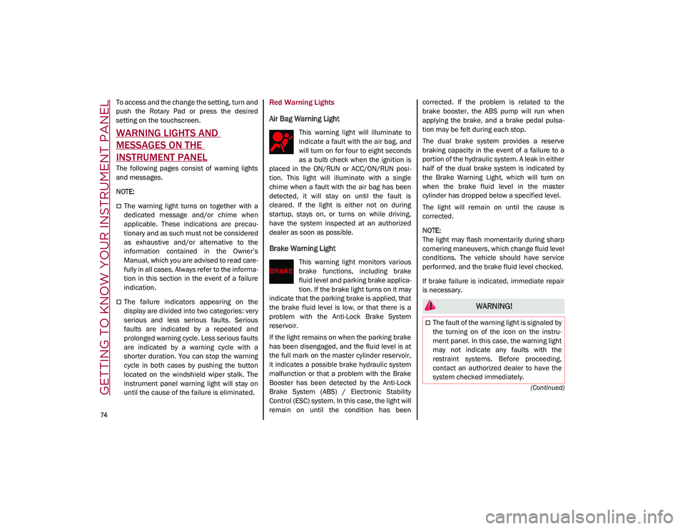
This warning light will illuminate to
indicate a fault with the air bag, and
will turn on for four to eight seconds
as a bulb check when the ignition is
placed in the ON/RUN or ACC/ON/RUN posi -
tion. This light will illuminate with a single
chime when a fault with the air bag has been
detected, it will stay on until the fault is
cleared. If the light is either not on during
startup, stays on, or turns on while driving,
have the system inspected at an authorized
dealer as soon as possible.
Brake Warning Light
This warning light monitors various
brake functions, including brake
fluid level and parking brake applica -
tion. If the brake light turns on it may
indicate that the parking brake is applied, that
the brake fluid level is low, or that there is a
problem with the Anti-Lock Brake System
reservoir.
If the light remains on when the parking brake
has been disengaged, and the fluid level is at
the full mark on the master cylinder reservoir,
it indicates a possible brake hydraulic system
malfunction or that a problem with the Brake
Booster has been detected by the Anti-Lock
Brake System (ABS) / Electronic Stability
Control (ESC) system. In this case, the light will
remain on until the condition has been corrected. If the problem is related to the
brake booster, the ABS pump will run when
applying the brake, and a brake pedal pulsa
-
tion may be felt during each stop.
The dual brake system provides a reserve
braking capacity in the event of a failure to a
portion of the hydraulic system. A leak in either
half of the dual brake system is indicated by
the Brake Warning Light, which will turn on
when the brake fluid level in the master
cylinder has dropped below a specified level.
The light will remain on until the cause is
corrected.
NOTE:
The light may flash momentarily during sharp
cornering maneuvers, which change fluid level
conditions. The vehicle should have service
performed, and the brake fluid level checked.
If brake failure is indicated, immediate repair
is necessary.
WARNING!
The fault of the warning light is signaled by
the turning on of the icon on the instru -
ment panel. In this case, the warning light
may not indicate any faults with the
restraint systems. Before proceeding,
contact an authorized dealer to have the
system checked immediately.
21_GU_OM_EN_USC_t.book Page 74
Page 77 of 280
75
Vehicles equipped with the Anti-Lock Brake
System (ABS) are also equipped with Elec-
tronic Brake Force Distribution (EBD). In the
event of an EBD failure, the Brake Warning
Light will turn on along with the ABS Light.
Immediate repair to the ABS system is
required.
Operation of the Brake Warning Light can be
checked by turning the ignition switch from the
OFF position to the ON/RUN position. The light
should illuminate for approximately two
seconds. The light should then turn off unless
the parking brake is applied or a brake fault is
detected. If the light does not illuminate, have
the light inspected by an authorized dealer.
The light also will turn on when the parking
brake is applied with the ignition switch in the
ON/RUN position.
NOTE:
This light shows only that the parking brake is
applied. It does not show the degree of brake
application.
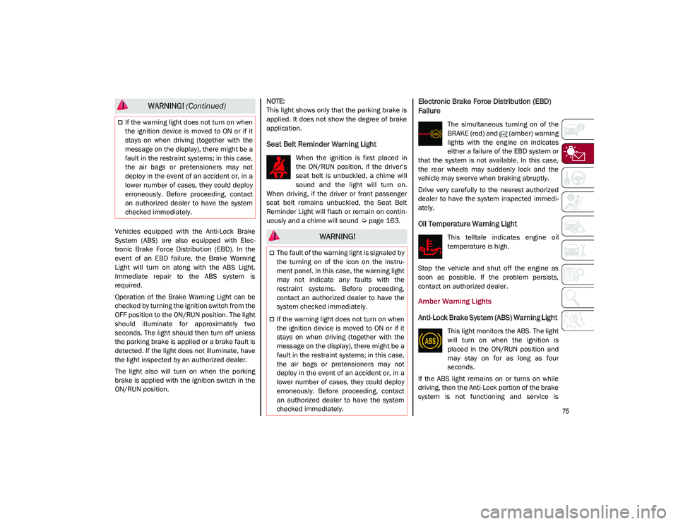
Seat Belt Reminder Warning Light
When the ignition is first placed in
the ON/RUN position, if the driver’s
seat belt is unbuckled, a chime will
sound and the light will turn on.
When driving, if the driver or front passenger
seat belt remains unbuckled, the Seat Belt
Reminder Light will flash or remain on contin -
uously and a chime will sound
Ú
page 163.
Electronic Brake Force Distribution (EBD)
Failure
The simultaneous turning on of the
BRAKE (red) and (amber) warning
lights with the engine on indicates
either a failure of the EBD system or
that the system is not available. In this case,
the rear wheels may suddenly lock and the
vehicle may swerve when braking abruptly.
Drive very carefully to the nearest authorized
dealer to have the system inspected immedi -
ately.
Oil Temperature Warning Light
This telltale indicates engine oil
temperature is high.
Stop the vehicle and shut off the engine as
soon as possible. If the problem persists,
contact an authorized dealer.
Amber Warning Lights
Anti-Lock Brake System (ABS) Warning Light
This light monitors the ABS. The light
will turn on when the ignition is
placed in the ON/RUN position and
may stay on for as long as four
seconds.
If the ABS light remains on or turns on while
driving, then the Anti-Lock portion of the brake
system is not functioning and service is
If the warning light does not turn on when
the ignition device is moved to ON or if it
stays on when driving (together with the
message on the display), there might be a
fault in the restraint systems; in this case,
the air bags or pretensioners may not
deploy in the event of an accident or, in a
lower number of cases, they could deploy
erroneously. Before proceeding, contact
an authorized dealer to have the system
checked immediately.
WARNING! (Continued)
WARNING!
The fault of the warning light is signaled by
the turning on of the icon on the instru -
ment panel. In this case, the warning light
may not indicate any faults with the
restraint systems. Before proceeding,
contact an authorized dealer to have the
system checked immediately.
If the warning light does not turn on when
the ignition device is moved to ON or if it
stays on when driving (together with the
message on the display), there might be a
fault in the restraint systems; in this case,
the air bags or pretensioners may not
deploy in the event of an accident or, in a
lower number of cases, they could deploy
erroneously. Before proceeding, contact
an authorized dealer to have the system
checked immediately.
21_GU_OM_EN_USC_t.book Page 75
Page 78 of 280
GETTING TO KNOW YOUR INSTRUMENT PANEL
76
required. However, the conventional brake
system will continue to operate normally if the
brake indicator light is not on.
If the ABS light is on, the brake system should
be serviced as soon as possible to restore the
benefits of Anti-Lock Brakes. If the ABS light
does not turn on when the ignition is placed in
the ON/RUN position, have the light inspected
by an authorized dealer.
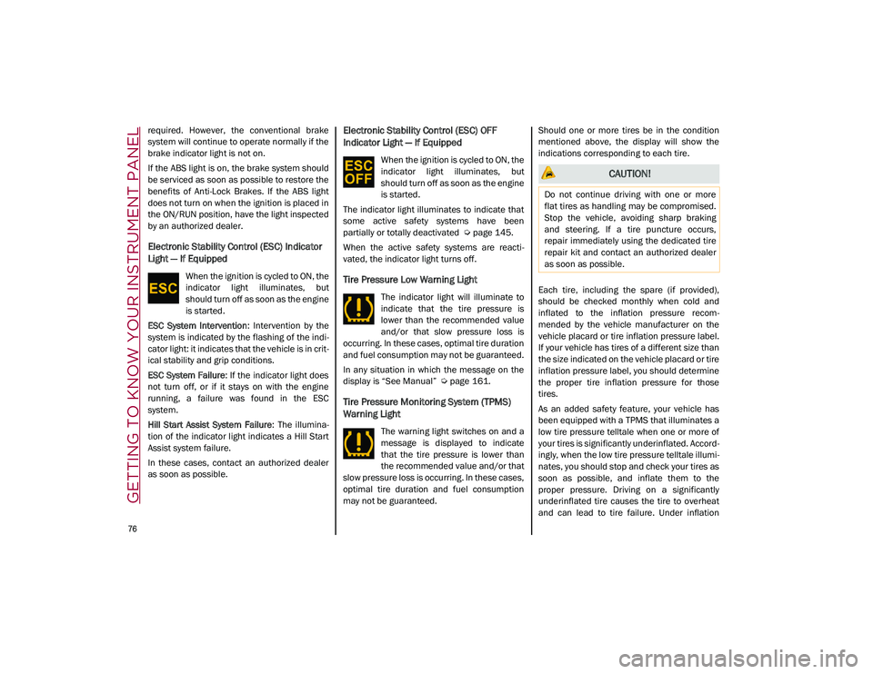
Electronic Stability Control (ESC) Indicator
Light — If Equipped
When the ignition is cycled to ON, the
indicator light illuminates, but
should turn off as soon as the engine
is started.
ESC System Intervention : Intervention by the
system is indicated by the flashing of the indi -
cator light: it indicates that the vehicle is in crit -
ical stability and grip conditions.
ESC System Failure : If the indicator light does
not turn off, or if it stays on with the engine
running, a failure was found in the ESC
system.
Hill Start Assist System Failure : The illumina-
tion of the indicator light indicates a Hill Start
Assist system failure.
In these cases, contact an authorized dealer
as soon as possible.
Electronic Stability Control (ESC) OFF
Indicator Light — If Equipped
When the ignition is cycled to ON, the
indicator light illuminates, but
should turn off as soon as the engine
is started.
The indicator light illuminates to indicate that
some active safety systems have been
partially or totally deactivated
Ú
page 145.
When the active safety systems are reacti -
vated, the indicator light turns off.
Tire Pressure Low Warning Light
The indicator light will illuminate to
indicate that the tire pressure is
lower than the recommended value
and/or that slow pressure loss is
occurring. In these cases, optimal tire duration
and fuel consumption may not be guaranteed.
In any situation in which the message on the
display is “See Manual”
Ú
page 161.
Tire Pressure Monitoring System (TPMS)
Warning Light
The warning light switches on and a
message is displayed to indicate
that the tire pressure is lower than
the recommended value and/or that
slow pressure loss is occurring. In these cases,
optimal tire duration and fuel consumption
may not be guaranteed. Should one or more tires be in the condition
mentioned above, the display will show the
indications corresponding to each tire.
Each tire, including the spare (if provided),
should be checked monthly when cold and
inflated to the inflation pressure recom
-
mended by the vehicle manufacturer on the
vehicle placard or tire inflation pressure label.
If your vehicle has tires of a different size than
the size indicated on the vehicle placard or tire
inflation pressure label, you should determine
the proper tire inflation pressure for those
tires.
As an added safety feature, your vehicle has
been equipped with a TPMS that illuminates a
low tire pressure telltale when one or more of
your tires is significantly underinflated. Accord -
ingly, when the low tire pressure telltale illumi -
nates, you should stop and check your tires as
soon as possible, and inflate them to the
proper pressure. Driving on a significantly
underinflated tire causes the tire to overheat
and can lead to tire failure. Under inflation
CAUTION!
Do not continue driving with one or more
flat tires as handling may be compromised.
Stop the vehicle, avoiding sharp braking
and steering. If a tire puncture occurs,
repair immediately using the dedicated tire
repair kit and contact an authorized dealer
as soon as possible.
21_GU_OM_EN_USC_t.book Page 76