Page 73 of 118

Periodic maintenance and adjustment
7-9
7 Clean the surface of the spark plug
gasket and its mating surface, and
then wipe off any grime from the spark
plug threads.
TIP
If a torque wrench is not available
when installing a spark plug, a good
estimate of the correct torque is 1/4…
1/2 turn past finger tight. However, the
spark plug should be tightened to the
specified torque as soon as possible.
EAU36112
Canister
This model is equipped with a canister
to prevent the discharging of fuel vapor
into the atmosphere. Before operating
this vehicle, make sure to check the
following:
Check each hose connection.
Check each hose and canister for
cracks or damage. Replace if
damaged.
Make sure that the canister
breather is not blocked, and if
necessary, clean it.
1. Spark plug gap
Spark plug gap:
0.7–0.8 mm (0.028–0.031 in)
Tightening torque:
Spark plug:
12.5 N·m (1.25 kgf·m, 9.22 lb·ft)1. Canister
2. Canister breather hose
2
1
ZAUM1458
UBL1E0E0.book Page 9 Thursday, May 11, 2017 8:51 AM
Page 74 of 118

Periodic maintenance and adjustment
7-10
7
EAUM3940
Engine oil and oil filter ele-
ment
The engine oil level should be checked
before each ride. In addition, the oil
must be changed and the oil filter ele-
ment replaced at the intervals specified
in the periodic maintenance and lubri-
cation chart and when the oil change
indicator comes on.
To check the engine oil level
1. Place the vehicle on the center-
stand. A slight tilt to the side can
result in a false reading.
2. Start the engine, warm it up for
several minutes, and then turn it
off.
3. Wait a few minutes until the oil set-
tles, remove the oil filler cap, wipe
the dipstick clean, insert it back
into the oil filler hole (without
screwing it in), and then remove it
again to check the oil level.
TIP
The engine oil should be between the
tip of the dipstick and the maximum
level mark.
4. If the engine oil is not between the
tip of the dipstick and the maxi-
mum level mark, add sufficient oil
of the recommended type to raise
it to the correct level.
5. Insert the dipstick into the oil filler
hole, and then tighten the oil filler
cap.
To change the engine oil (with or
without oil filter element replace-
ment)
1. Place the vehicle on the center-
stand.
2. Start the engine, warm it up for
several minutes, and then turn it
off.
3. Place an oil pan under the engine
to collect the used oil.
4. Remove the engine oil filler cap,
the engine oil drain bolt and its
gasket to drain the oil from the
crankcase.
TIP
Skip steps 5…7 if the oil filter element is
not being replaced.
5. Remove the oil filter element cover
by removing the bolts. NOTICE:
When removing the oil filter ele-1. Engine oil filler cap
2. Dipstick
3. Maximum level mark
4. Tip of the engine oil dipstick
ZAUM1028
3
4
1
2
1. Engine oil drain bolt
2. Gasket
12
UBL1E0E0.book Page 10 Thursday, May 11, 2017 8:51 AM
Page 75 of 118
![YAMAHA XMAX 400 2020 Owners Manual Periodic maintenance and adjustment
7-11
7 ment cover, the compression
spring will fall out. Take care not
to lose the compression spring.
[ECA12912]
6. Remove and replace the oil filter
element and O](/manual-img/51/52977/w960_52977-74.png "YAMAHA XMAX 400 2020 Owners Manual Periodic maintenance and adjustment
7-11
7 ment cover, the compression
spring will fall out. Take care not
to lose the compression spring.
[ECA12912]
6. Remove and replace the oil filter
element and O")
Periodic maintenance and adjustment
7-11
7 ment cover, the compression
spring will fall out. Take care not
to lose the compression spring.
[ECA12912]
6. Remove and replace the oil filter
element and O-rings.
7. Install the compression spring and
oil filter element cover by installing
the bolts, then tightening them to
the specified torque.
TIP
Make sure that the O-rings are properly
seated.
8. Install the engine oil drain bolt and
its new gasket, and then tighten
the bolt to the specified torque.
9. Refill with the specified amount of
the recommended engine oil, and
then install and tighten the oil filler
cap.
TIP
Be sure to wipe off spilled oil on any
parts after the engine and exhaust sys-
tem have cooled down.
NOTICE
ECA11671
Do not use oils with a diesel
specification of “CD” or oils of a
higher quality than specified. In
addition, do not use oils labeled
“ENERGY CONSERVING II” or
higher.
Be sure no foreign material en-
ters the crankcase.
1. Bolt
2. Oil filter element cover
1. Oil filter element cover
2. O-ring
3. Compression spring
4. Oil filter element
Tightening torque:
Oil filter element cover bolt:
10 N·m (1.0 kgf·m, 7.4 lb·ft)
21
12
43
Tightening torque:
Engine oil drain bolt:
20 N·m (2.0 kgf·m, 15 lb·ft)
Recommended engine oil:
See page 9-1.
Oil quantity:
Oil change:
1.50 L (1.59 US qt, 1.32 Imp.qt)
With oil filter removal:
1.70 L (1.80 US qt, 1.50 Imp.qt)
UBL1E0E0.book Page 11 Thursday, May 11, 2017 8:51 AM
Page 76 of 118

Periodic maintenance and adjustment
7-12
710. Start the engine, and then let it idle
for several minutes while checking
it for oil leakage. If oil is leaking,
immediately turn the engine off
and check for the cause.
11. Reset the oil change indicator.
(See page 4-7.)
TIP
If the engine oil is changed before the
oil change indicator comes on (i.e. be-
fore the periodic oil change interval has
been reached), the indicator must be
reset after the oil change for the next
periodic oil change to be indicated at
the correct time.
EAU20067
Final transmission oil
The final transmission case must be
checked for oil leakage before each
ride. If any leakage is found, have a
Yamaha dealer check and repair the
scooter. In addition, the final transmis-
sion oil must be changed as follows at
the intervals specified in the periodic
maintenance and lubrication chart.
1. Start the engine, warm up the final
transmission oil by riding the
scooter for several minutes, and
then stop the engine.
2. Place the scooter on the center-
stand.
3. Place an oil pan under the final
transmission case to collect the
used oil.
4. Remove the final transmission oil
filler cap and its O-ring from the fi-
nal transmission case.
5. Remove the final transmission oil
drain bolt and its gasket to drain
the oil from the final transmission
case.
1. Final transmission oil filler cap
2. O-ring
3. Final transmission oil drain bolt
4. Gasket
2
1
3
4
UBL1E0E0.book Page 12 Thursday, May 11, 2017 8:51 AM
Page 77 of 118

Periodic maintenance and adjustment
7-13
7 6. Install the final transmission oil
drain bolt and its new gasket, and
then tighten the bolt to the speci-
fied torque.
7. Refill with the specified amount of
the recommended final transmis-
sion oil. WARNING! Make sure
that no foreign material enters
the final transmission case.
Make sure that no oil gets on
the tire or wheel.
[EWA11312]
8. Install the final transmission oil fill-
er cap and its new O-ring, and
then tighten the oil filler cap.
9. Check the final transmission case
for oil leakage. If oil is leaking,
check for the cause.
EAU20071
Coolant
The coolant level should be checked
before each ride. In addition, the cool-
ant must be changed at the intervals
specified in the periodic maintenance
and lubrication chart.
EAU78580To check the coolant level
1. Place the vehicle on the center-
stand.
TIP
The coolant level must be
checked on a cold engine since
the level varies with engine tem-
perature.
Make sure that the vehicle is posi-
tioned straight up when checking
the coolant level. A slight tilt to the
side can result in a false reading.
2. Check the coolant level through
the check window.
TIP
The coolant should be between the
minimum and maximum level marks.
Tightening torque:
Final transmission oil drain bolt:
20 N·m (2.0 kgf·m, 15 lb·ft)
Recommended final transmission
oil:
See page 9-1.
Oil quantity:
0.25 L (0.26 US qt, 0.22 Imp.qt)
1. Coolant level check window
2. Maximum level mark
3. Minimum level mark
1
2
3
UBL1E0E0.book Page 13 Thursday, May 11, 2017 8:51 AM
Page 78 of 118

Periodic maintenance and adjustment
7-14
73. If the coolant is at or below the
minimum level mark, remove the
left floorboard mat by pulling it up.
4. Remove the coolant reservoir cov-
er.
5. Remove the coolant reservoir cap,
add coolant to the maximum level
mark, and then install the reservoir
cap. WARNING! Remove only
the coolant reservoir cap. Never
attempt to remove the radiator
cap when the engine is hot.
[EWA15162] NOTICE: If coolant is not
available, use distilled water or
soft tap water instead. Do not
use hard water or salt water
since it is harmful to the engine.
If water has been used instead
of coolant, replace it with cool-
ant as soon as possible, other-
wise the cooling system will notbe protected against frost and
corrosion. If water has been
added to the coolant, have a
Yamaha dealer check the anti-
freeze content of the coolant as
soon as possible, otherwise the
effectiveness of the coolant will
be reduced.
[ECA10473]
6. Install the coolant reservoir cover.
7. Place the left floorboard mat in the
original position and push it down-
ward to secure it.
EAU33032Changing the coolant
The coolant must be changed at the in-
tervals specified in the periodic mainte-
nance and lubrication chart. Have a
Yamaha dealer change the coolant.
WARNING! Never attempt to remove
the radiator cap when the engine is
hot.
[EWA10382]
1. Floorboard mat
1. Coolant reservoir cover
1
1
1. Coolant reservoir cap
Coolant reservoir capacity (up to
the maximum level mark):
0.18 L (0.19 US qt, 0.16 Imp.qt)
1
UBL1E0E0.book Page 14 Thursday, May 11, 2017 8:51 AM
Page 79 of 118
Periodic maintenance and adjustment
7-15
7
EAUM3051
Air filter elements and check
hoses and V-belt case air filter
element
The air filter elements and the V-belt
case air filter element should be ser-
viced at the intervals specified in the
periodic maintenance and lubrication
chart. Service all air filter elements
more frequently if you are riding in un-
usually wet or dusty areas.
Replacing the air filter elements
1. Place the scooter on the center-
stand.
TIP
Continue as follows for each air filter el-
ement.
2. Remove the air filter case cover by
removing the rubber caps and
screws.
LeftRight
3. Pull the air filter element out.
Left
Right
4. Insert a new air filter element into
the air filter case.
1. Screw
2. Air filter case cover
3. Rubber cap
1
2
1
1
3
3
1. Screw
2. Air filter case cover
3. Rubber cap
1. Air filter element
1. Air filter element
1
1
2
3
1
1
UBL1E0E0.book Page 15 Thursday, May 11, 2017 8:51 AM
Page 80 of 118

Periodic maintenance and adjustment
7-16
75. Install the air filter case cover by
installing the screws. NOTICE:
Make sure that each filter ele-
ment is properly seated in its
case. Always replace both air fil-
ter elements at the same time,
otherwise poor engine perfor-
mance or damage to the engine
may result. The engine should
never be operated without the
filter elements installed, other-
wise the piston(s) and/or cylin-
der(s) may become excessively
worn.
[ECA12924]
6. Install the rubber caps.
To clean the air filter check hoses
1. Check the hose at the bottom of
both air filter cases for accumulat-
ed dirt or water.
LeftRight
2. If dirt or water is visible, remove
the hose, clean it, and then install
it.
Cleaning the V-belt case air filter el-
ement
1. Remove panel A. (See page 7-7.)
2. Remove the left air filter case cov-
er.
3. Remove the V-belt air filter case
cover by removing the screws.
4. Remove the V-belt case air filter
element by removing the screws.
1. Air filter check hose
1
1. Air filter check hose
1. Screw
2. V-belt air filter case cover
1
ZAUM1031
2
11
UBL1E0E0.book Page 16 Thursday, May 11, 2017 8:51 AM
 1
1 2
2 3
3 4
4 5
5 6
6 7
7 8
8 9
9 10
10 11
11 12
12 13
13 14
14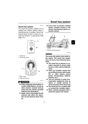 15
15 16
16 17
17 18
18 19
19 20
20 21
21 22
22 23
23 24
24 25
25 26
26 27
27 28
28 29
29 30
30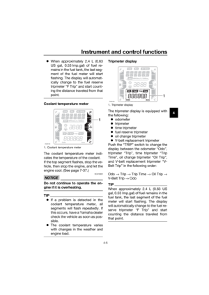 31
31 32
32 33
33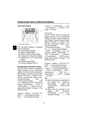 34
34 35
35 36
36 37
37 38
38 39
39 40
40 41
41 42
42 43
43 44
44 45
45 46
46 47
47 48
48 49
49 50
50 51
51 52
52 53
53 54
54 55
55 56
56 57
57 58
58 59
59 60
60 61
61 62
62 63
63 64
64 65
65 66
66 67
67 68
68 69
69 70
70 71
71 72
72 73
73 74
74 75
75 76
76 77
77 78
78 79
79 80
80 81
81 82
82 83
83 84
84 85
85 86
86 87
87 88
88 89
89 90
90 91
91 92
92 93
93 94
94 95
95 96
96 97
97 98
98 99
99 100
100 101
101 102
102 103
103 104
104 105
105 106
106 107
107 108
108 109
109 110
110 111
111 112
112 113
113 114
114 115
115 116
116 117
117