Page 25 of 118

Smart key system
3-11
3 To lock the steering
1. Turn the handlebar all the way to
the left.
2. With the smart key turned on and
within operating range, push the
main switch knob.
3. While the smart key system indi-
cator light is on, push and turn the
main switch to “ ”.
TIP
If the steering will not lock, try turning
the handlebar back to the right slightly.
To unlock the steering
1. With the smart key turned on and
within operating range, push the
main switch knob.
2. While the smart key system indi-
cator light is on, push and turn the
main switch to the desired posi-
tion.
EAU76903 (parking)
The hazard lights and turn signal lights
can be turned on, but all other electri-
cal systems are off.To use the “ ” position
1. With the main switch in the “ ”
position and the smart key turned
on and within operating range,
push the main switch knob.
2. While the smart key system indi-
cator is light on, turn the main
switch to “ ”.
To exit the “ ” position
Simply turn the main switch to “ ”.
NOTICE
ECA20760
Using the hazard or turn signal lights
for an extended length of time may
cause the battery to discharge.
EAU79000“ ” (fuel tank cap lid)
To open the fuel tank cap lid
1. With the smart key turned on and
within operating range, push the
main switch knob.
2. While the smart key system indi-
cator light is on, turn the main
switch to “ ”.
To close the fuel tank cap lid
Push the fuel tank cap lid down until it
is closed.
1. Push.
2. Push and turn.
ZAUM1476
12
1. Push.
2. Turn.
ZAUM1477
1
2
UBL1E0E0.book Page 11 Thursday, May 11, 2017 8:51 AM
Page 26 of 118
Smart key system
3-12
3
TIP
Make sure that fuel tank cap lid is se-
curely closed before starting off.
UBL1E0E0.book Page 12 Thursday, May 11, 2017 8:51 AM
Page 27 of 118

Instrument and control functions
4-1
4
EAU4939C
Indicator lights and warning
lights
EAU11032Turn signal indicator lights “ ”
and“”
Each indicator light will flash when its
corresponding turn signal lights are
flashing.
EAU11081High beam indicator light “ ”
This indicator light comes on when the
high beam of the headlight is switched
on.
EAU78180Engine trouble warning light “ ”
This warning light comes on if a prob-
lem is detected in the engine or other
vehicle control system. If this occurs,
have a Yamaha dealer check the on-
board diagnostic system.The electrical circuit of the warning
light can be checked by turning the
main switch to “ON”. The warning light
should come on for a few seconds, and
then go off.
If the warning light does not come on
initially when the main switch is turned
to “ON”, or if the warning light remains
on, have a Yamaha dealer check the
vehicle.
EAU78171ABS warning light “ ”
In normal operation, the ABS warning
light comes on when the main switch is
turned to “ON”, and goes off after trav-
eling at a speed of 10 km/h (6 mi/h) or
higher.
If the ABS warning light:
does not come on when the main
switch is turned to “ON”
comes on or flashes while riding
does not go off after traveling at a
speed of 10 km/h (6 mi/h) or high-
er
The ABS may not work correctly. If any
of the above occurs, have a Yamaha
dealer check the system as soon as
possible. (See page 4-15 for an expla-
nation of the ABS.)
WARNING
EWA16041
If the ABS warning light does not go
off after traveling at a speed of 10
km/h (6 mi/h) or higher, or if the
warning light comes on or flashes
while riding, the brake system re-
verts to conventional braking. If ei-
ther of the above occurs, or if the
warning light does not come on at
all, use extra caution to avoid possi-
ble wheel lock during emergency
1. Left turn signal indicator light “ ”
2. Right turn signal indicator light “ ”
3. High beam indicator light “ ”
4. Anti-lock Brake System (ABS) warning
light “ ”
5. Engine trouble warning light “ ”
6. Traction control system indicator light “ ”
7. Smart key system indicator light “ ”
ZAUM1478
12
ABS
ABS
UBL1E0E0.book Page 1 Thursday, May 11, 2017 8:51 AM
Page 28 of 118

Instrument and control functions
4-2
4braking. Have a Yamaha dealer
check the brake system and electri-
cal circuits as soon as possible.
TIP
The ABS warning light may come on
while accelerating the engine with the
vehicle on its centerstand, but this
does not indicate a malfunction.
If this happens, turn the main switch off
and then back on again to reset the in-
dicator light.
EAU78591Traction control system indicator
light “TCS”
This indicator light will flash when trac-
tion control has engaged.
If the traction control system is turned
off, this indicator light will come on.
(See page 4-16.)
TIP
When the vehicle is turned on, the light
should come on for a few seconds and
then go off. If the light does not come
on, or if the light remains on, have a
Yamaha dealer check vehicle.
EAU78600Smart key system indicator
light “ ”
This indicator light communicates the
status of the smart key system. When
the smart key system is operating nor-
mally, this indicator light will be off. If
there is an error in the smart key sys-
tem, the indicator light will flash. The
indicator light will also flash when com-
munication between the vehicle and
smart key takes place and when cer-
tain smart key system operations are
carried out.
EAU63544
Speedometer
For the UK
The speedometer shows the vehicle’s
traveling speed.
When the vehicle power is turned on,
the speedometer needle will sweep
once across the speed range and then
return to zero in order to test the elec-
trical circuit.
1. Speedometer
1. Speedometer
ZAUM1479
1
ZAUM1526
1
UBL1E0E0.book Page 2 Thursday, May 11, 2017 8:51 AM
Page 29 of 118

Instrument and control functions
4-3
4
EAU63551
Tachometer
The electric tachometer allows the rid-
er to monitor the engine speed and
keep it within the ideal power range.
When the vehicle power is turned on,
the tachometer needle will sweep once
across the r/min range and then return
to zero r/min in order to test the electri-
cal circuit.
NOTICE
ECA10032
Do not operate the engine in the ta-
chometer red zone.
Red zone: 8200 r/min and above
EAU78485
Multi-function display
WARNING
EWA12423
Be sure to stop the vehicle before
making any setting changes to the
multi-function meter unit. Changing
settings while riding can distract the
operator and increase the risk of an
accident.
The “TRIP/INFO” switch is located on
the right side of the handlebar. This
switch allows you to control or change
the settings of the multi-function meter
unit. To use the “TRIP” switch, move
the “TRIP/INFO” switch in direction (a).
To use the “INFO” switch, move the
“TRIP/INFO” switch in direction (b).
1. Tachometer
2. Tachometer red zone
ZAUM1480
1
2
1. Fuel meter
2. Information display
3. Coolant temperature meter
4. Clock
5. Tripmeter display
6. Icy road warning indicator Ž
ZAUM1481
2
3
4
1
6
5
UBL1E0E0.book Page 3 Thursday, May 11, 2017 8:51 AM
Page 30 of 118

Instrument and control functions
4-4
4The multi-function display is equipped
with the following:
clock
fuel meter
coolant temperature meter
tripmeter display
information display
TIP
For the UK: To switch the displays be-
tween kilometers and miles, turn the
onds.
Clock
The clock uses a 24-hour time system.
To set the clock
1. Turn the main switch to “OFF”.2. Push and hold the “TRIP” switch.
3. Turn the main switch to “ON”
while pushing the “TRIP” switch,
and then continue to push the
“TRIP” switch for eight seconds.
The hour digits will start flashing.
4. Use the “TRIP” switch to set the
hours.
5. Push the “TRIP” switch for three
seconds, and then release it. The
minute digits will start flashing.
6. Use the “TRIP” switch to set the
minutes.
7. Push the “TRIP” switch for three
seconds, and then release it to
start the clock.
Fuel meter
The fuel meter indicates the amount of
fuel in the fuel tank. The segments of
the fuel meter disappear from “F” (full)
towards “E” (empty) as the fuel level
decreases. When the last segment of
the fuel meter starts flashing, refuel as
soon as possible.
TIP
If a problem is detected in the fuel
meter, the all segments will flash
repeatedly. If this occurs, have a
Yamaha dealer check the vehicle.
1. “TRIP/INFO” switch
1. Clock
1(b) (a)
ZAUM1482
1
1. Fuel meter
ZAUM1483
1
UBL1E0E0.book Page 4 Thursday, May 11, 2017 8:51 AM
Page 31 of 118
 of fuel re-
mains in the fuel tank, the last seg-
ment of the fuel meter will start
flashing. The display")
Instrument and control functions
4-5
4 When approximately 2.4 L (0.63
US gal, 0.53 Imp.gal) of fuel re-
mains in the fuel tank, the last seg-
ment of the fuel meter will start
flashing. The display will automat-
ically change to the fuel reserve
tripmeter “F Trip” and start count-
ing the distance traveled from that
point.
Coolant temperature meter
The coolant temperature meter indi-
cates the temperature of the coolant.
If the top segment flashes, stop the ve-
hicle, then stop the engine, and let the
engine cool. (See page 7-37.)
NOTICE
ECA10022
Do not continue to operate the en-
gine if it is overheating.
TIP
If a problem is detected in the
coolant temperature meter, all
segments will flash repeatedly. If
this occurs, have a Yamaha dealer
check the vehicle as soon as pos-
sible.
The coolant temperature varies
with changes in the weather and
engine load.
Tripmeter display
The tripmeter display is equipped with
the following:
odometer
tripmeter
time tripmeter
fuel reserve tripmeter
oil change tripmeter
V-belt replacement tripmeter
Push the “TRIP” switch to change the
display between the odometer “Odo”,
tripmeter “Trip”, time tripmeter “Trip
Time”, oil change tripmeter “Oil Trip”,
and V-belt replacement tripmeter “V-
Belt Trip” in the following order:
Odo → Trip → Trip Time → Oil Trip →
V-Belt Trip → Odo
TIP
When approximately 2.4 L (0.63 US
gal, 0.53 Imp.gal) of fuel remains in the
fuel tank, the last segment of the fuel
meter will start flashing. The display
will automatically change to the fuel re-
counting the distance traveled from
that point.
1. Coolant temperature meter
ZAUM1484
1
1. Tripmeter display
ZAUM1485
1
UBL1E0E0.book Page 5 Thursday, May 11, 2017 8:51 AM
Page 32 of 118

Instrument and control functions
4-6
4Odometer “Odo” and tripmeter
“Trip”
The odometer shows the total distance
traveled by the vehicle.
The tripmeter shows the distance trav-
eled since it was last reset.
To reset the tripmeter, select it by
pushing the “TRIP” switch, and then
push the “TRIP” switch for three sec-
onds.
TIP
The odometer will lock at 999999.
The tripmeter will reset and con-
tinue counting after 9999.9 is
reached.
Time tripmeter “Time”
The time tripmeter displays the time
that has elapsed while the main switch
was in the “ON” position since it was
last reset.
The maximum time that can be shown
is 99:59.
TIP
To reset the time tripmeter, select it by
onds.
Fuel reserve tripmeter “F Trip”
When approximately 2.4 L (0.63 US
gal, 0.53 Imp.gal) of fuel remains in the
fuel tank, the last segment of the fuel
meter will start flashing. The display
will automatically change to the fuel re-
serve tripmeter “F Trip” and start
counting the distance traveled from
that point. In this case, push the “TRIP”
switch to switch the display in the fol-
lowing order:
F Trip → Oil Trip → V-Belt Trip → Odo
→ Trip → Trip Time → F Trip
To reset the fuel reserve tripmeter, se-
lect it by pushing the “TRIP” switch,
and then push the “TRIP” switch for
three seconds.
The fuel reserve tripmeter will reset au-
tomatically and disappear after refuel-
ing and traveling 5 km (3 mi).
1. Time tripmeter
ZAUM1486
1
1. Fuel reserve tripmeter
ZAUM1487
1
UBL1E0E0.book Page 6 Thursday, May 11, 2017 8:51 AM
 1
1 2
2 3
3 4
4 5
5 6
6 7
7 8
8 9
9 10
10 11
11 12
12 13
13 14
14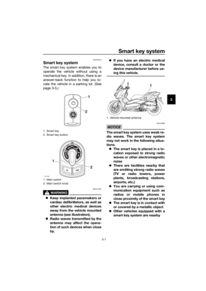 15
15 16
16 17
17 18
18 19
19 20
20 21
21 22
22 23
23 24
24 25
25 26
26 27
27 28
28 29
29 30
30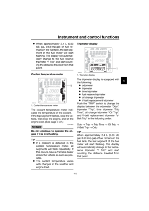 31
31 32
32 33
33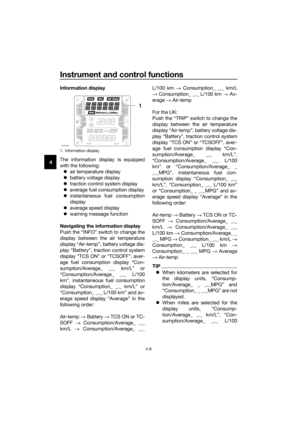 34
34 35
35 36
36 37
37 38
38 39
39 40
40 41
41 42
42 43
43 44
44 45
45 46
46 47
47 48
48 49
49 50
50 51
51 52
52 53
53 54
54 55
55 56
56 57
57 58
58 59
59 60
60 61
61 62
62 63
63 64
64 65
65 66
66 67
67 68
68 69
69 70
70 71
71 72
72 73
73 74
74 75
75 76
76 77
77 78
78 79
79 80
80 81
81 82
82 83
83 84
84 85
85 86
86 87
87 88
88 89
89 90
90 91
91 92
92 93
93 94
94 95
95 96
96 97
97 98
98 99
99 100
100 101
101 102
102 103
103 104
104 105
105 106
106 107
107 108
108 109
109 110
110 111
111 112
112 113
113 114
114 115
115 116
116 117
117