Page 495 of 613
6-22
What to do in an emergency
Follow these steps to change your
vehicle's tyre:
1. Park on a level, firm surface.
2. Move the shift lever into P (Park),
apply the parking brake, and place
the ignition switch in the LOCK/
OFF position.
3. Press the hazard warning flasher
button.
4. Remove the wheel brace, jack,
jack handle, and spare tyre from
the vehicle.
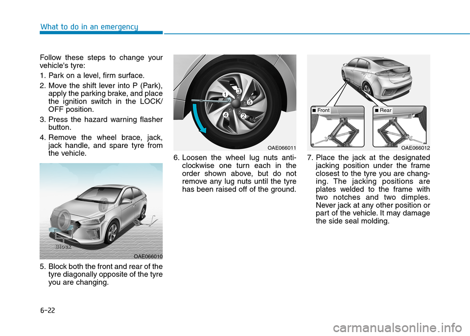
5. Block both the front and rear of the
tyre diagonally opposite of the tyre
you are changing.6. Loosen the wheel lug nuts anti-
clockwise one turn each in the
order shown above, but do not
remove any lug nuts until the tyre
has been raised off of the ground.7. Place the jack at the designated
jacking position under the frame
closest to the tyre you are chang-
ing. The jacking positions are
plates welded to the frame with
two notches and two dimples.
Never jack at any other position or
part of the vehicle. It may damage
the side seal molding.
OAE066010
B B B B
l l l l
o o o o
c c c c
k k k k
OAE066011OAE066012
■Front■Rear
Page 506 of 613
6-33
What to do in an emergency
6
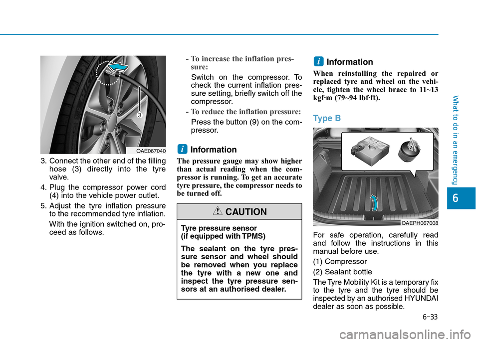
3. Connect the other end of the filling
hose (3) directly into the tyre
valve.
4. Plug the compressor power cord
(4) into the vehicle power outlet.
5. Adjust the tyre inflation pressure
to the recommended tyre inflation.
With the ignition switched on, pro-
ceed as follows.
- To increase the inflation pres-
sure:
Switch on the compressor. To
check the current inflation pres-
sure setting, briefly switch off the
compressor.
- To reduce the inflation pressure:
Press the button (9) on the com-
pressor.
Information
The pressure gauge may show higher
than actual reading when the com-
pressor is running. To get an accurate
tyre pressure, the compressor needs to
be turned off.
Information
When reinstalling the repaired or
replaced tyre and wheel on the vehi-
cle, tighten the wheel brace to 11~13
kgf·m (79~94 lbf·ft).
Ty p e B
For safe operation, carefully read
and follow the instructions in this
manual before use.
(1) Compressor
(2) Sealant bottle
The Tyre Mobility Kit is a temporary fix
to the tyre and the tyre should be
inspected by an authorised HYUNDAI
dealer as soon as possible.
i
i
Tyre pressure sensor
(if equipped with TPMS)
The sealant on the tyre pres-
sure sensor and wheel should
be removed when you replace
the tyre with a new one and
inspect the tyre pressure sen-
sors at an authorised dealer.
CAUTION
OAEPH067008
OAE067040
Page 513 of 613
6-40
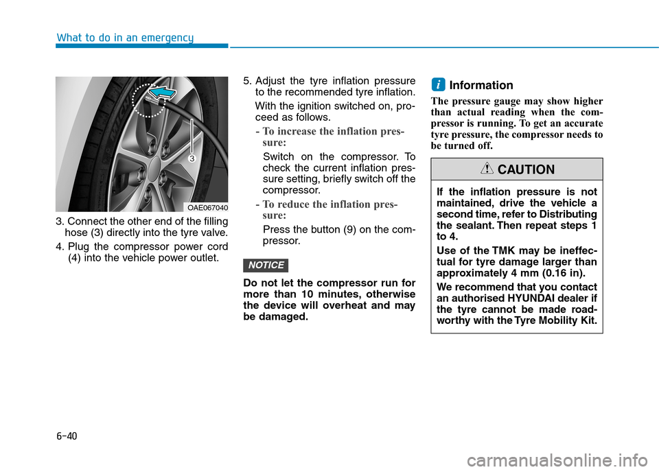
3. Connect the other end of the filling
hose (3) directly into the tyre valve.
4. Plug the compressor power cord
(4) into the vehicle power outlet.5. Adjust the tyre inflation pressure
to the recommended tyre inflation.
With the ignition switched on, pro-
ceed as follows.
- To increase the inflation pres-
sure:
Switch on the compressor. To
check the current inflation pres-
sure setting, briefly switch off the
compressor.
- To reduce the inflation pres-
sure:
Press the button (9) on the com-
pressor.
Do not let the compressor run for
more than 10 minutes, otherwise
the device will overheat and may
be damaged.
Information
The pressure gauge may show higher
than actual reading when the com-
pressor is running. To get an accurate
tyre pressure, the compressor needs to
be turned off.
i
NOTICE
What to do in an emergency
If the inflation pressure is not
maintained, drive the vehicle a
second time, refer to Distributing
the sealant. Then repeat steps 1
to 4.
Use of the TMK may be ineffec-
tual for tyre damage larger than
approximately 4 mm (0.16 in).
We recommend that you contact
an authorised HYUNDAI dealer if
the tyre cannot be made road-
worthy with the Tyre Mobility Kit.
CAUTION
OAE067040
Page 516 of 613
6-43
What to do in an emergency
6
When towing your vehicle in an
emergency without wheel dollies:
1. Place the ignition switch in the
ACC position.
2. Place the shift lever in N (Neutral).
3. Release the parking brake.Removable towing hook
1. Open the tailgate, and remove the
towing hook from the tool case.
2. Remove the hole cover by press-
ing the lower part of the cover on
the bumper.
3. Install the towing hook by turning it
clockwise into the hole until it is
fully secured.
4. Remove the towing hook and
install the cover after use. Failure to place the shift lever in
N (Neutral) may cause internal
damage to the transmission.
CAUTION
OAE066021
OAE066022
OAE066028
■Front
■Rear
Page 517 of 613
6-44
What to do in an emergency
Emergency towing
If towing is necessary, we recom-
mend you have it done by an autho-
rised HYUNDAI dealer or a commer-
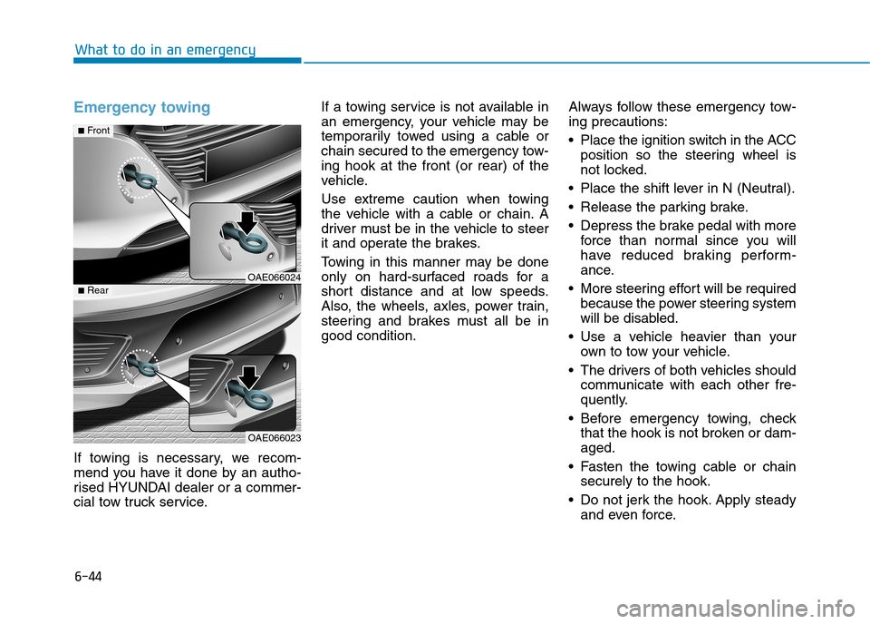
cial tow truck service.If a towing service is not available in
an emergency, your vehicle may be
temporarily towed using a cable or
chain secured to the emergency tow-
ing hook at the front (or rear) of the
vehicle.
Use extreme caution when towing
the vehicle with a cable or chain. A
driver must be in the vehicle to steer
it and operate the brakes.
Towing in this manner may be done
only on hard-surfaced roads for a
short distance and at low speeds.
Also, the wheels, axles, power train,
steering and brakes must all be in
good condition.Always follow these emergency tow-
ing precautions:
Place the ignition switch in the ACC
position so the steering wheel is
not locked.
Place the shift lever in N (Neutral).
Release the parking brake.
Depress the brake pedal with more
force than normal since you will
have reduced braking perform-
ance.
More steering effort will be required
because the power steering system
will be disabled.
Use a vehicle heavier than your
own to tow your vehicle.
The drivers of both vehicles should
communicate with each other fre-
quently.
Before emergency towing, check
that the hook is not broken or dam-
aged.
Fasten the towing cable or chain
securely to the hook.
Do not jerk the hook. Apply steady
and even force.
OAE066024
OAE066023
■Front
■Rear
Page 524 of 613
7-6
Maintenance
O OW
WN
NE
ER
R
M
MA
AI
IN
NT
TE
EN
NA
AN
NC
CE
E
The following lists are vehicle checks
and inspections that should be per-
formed by the owner or an authorised
HYUNDAI dealer at the frequencies
indicated to help ensure safe,
dependable operation of your vehicle.
Any adverse conditions should be
brought to the attention of your deal-
er as soon as possible.
These Owner Maintenance vehicle
checks are generally not covered by
warranties and you may be charged
for labour, parts and lubricants used.
How to Disconnect the (-)
Cable for Regular Maintenance
When the vehicle is under regular
maintenance, make sure to separate
the (-) cable before maintenance.
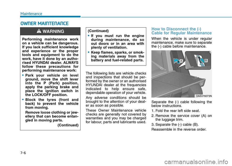
Separate the (-) cable following the
below instructions.
1. Fold the rear left side seat.
2. Remove the service cover (A) on
the luggage trim.
3. Separate the (-) cable (B).
Reassemble in the reverse order. Performing maintenance work
on a vehicle can be dangerous.
If you lack sufficient knowledge
and experience or the proper
tools and equipment to do the
work, have it done by an autho-
rised HYUNDAI dealer. ALWAYS
follow these precautions for
performing maintenance work:
Park your vehicle on level
ground, move the shift lever
into the P (Park) position,
apply the parking brake and
place the ignition switch in
the LOCK/OFF position.
Block the tyres (front and
back) to prevent the vehicle
from moving.
Remove loose clothing or jew-
ellery that can become entan-
gled in moving parts.
(Continued)
WARNING (Continued)
If you must run the engine
during maintenance, do so
out doors or in an area with
plenty of ventilation.
Keep flames, sparks, or smok-
ing materials away from the
battery and fuel-related parts.
OAE076073N
AB
Page 550 of 613
7-32
Maintenance
B BA
AT
TT
TE
ER
RY
Y
(
(1
12
2
V
VO
OL
LT
T,
,
P
PL
LU
UG
G-
-I
IN
N
H
HY
YB
BR
RI
ID
D
V
VE
EH
HI
IC
CL
LE
E)
)
When you do not use the vehicle
for a long time in a low tempera-
ture area, disconnect the battery
and keep it indoors.
Always charge the battery fully
to prevent battery case damage
in low temperature areas.
NOTICE
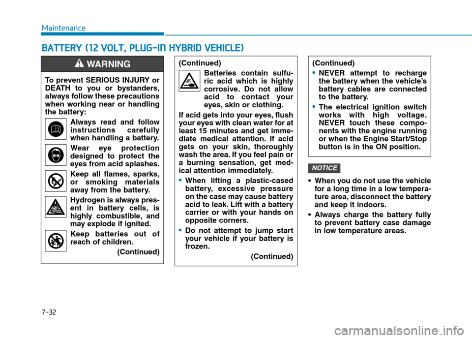
To prevent SERIOUS INJURY or
DEATH to you or bystanders,
always follow these precautions
when working near or handling
the battery:
Always read and follow
instructions carefully
when handling a battery.
Wear eye protection
designed to protect the
eyes from acid splashes.
Keep all flames, sparks,
or smoking materials
away from the battery.
Hydrogen is always pres-
ent in battery cells, is
highly combustible, and
may explode if ignited.
Keep batteries out of
reach of children.
(Continued)
WARNING (Continued)
Batteries contain sulfu-
ric acid which is highly
corrosive. Do not allow
acid to contact your
eyes, skin or clothing.
If acid gets into your eyes, flush
your eyes with clean water for at
least 15 minutes and get imme-
diate medical attention. If acid
gets on your skin, thoroughly
wash the area. If you feel pain or
a burning sensation, get med-
ical attention immediately.
When lifting a plastic-cased
battery, excessive pressure
on the case may cause battery
acid to leak. Lift with a battery
carrier or with your hands on
opposite corners.
Do not attempt to jump start
your vehicle if your battery is
frozen.
(Continued)
(Continued)
NEVER attempt to recharge
the battery when the vehicle’s
battery cables are connected
to the battery.
The electrical ignition switch
works with high voltage.
NEVER touch these compo-
nents with the engine running
or when the Engine Start/Stop
button is in the ON position.
Page 570 of 613
7-52
Maintenance
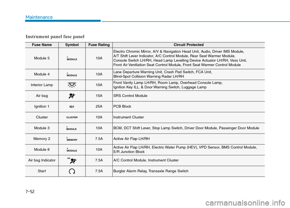
Instrument panel fuse panel
Fuse NameSymbolFuse RatingCircuit Protected
Module 5MODULE510A
Electro Chromic Mirror, A/V & Navigation Head Unit, Audio, Driver IMS Module,
A/T Shift Lever Indicator, A/C Control Module, Rear Seat Warmer Module,
Console Switch LH/RH, Head Lamp Levelling Device Actuator LH/RH, Vess Unit,
Front Air Ventilation Seat Control Module, Front Seat Warmer Control Module
Module 4MODULE410ALane Departure Warning Unit, Crash Pad Switch, FCA Unit,
Blind-Spot Collision Warning Radar LH/RH
Interior Lamp10AFront Vanity Lamp LH/RH, Room Lamp, Overhead Console Lamp,
Ignition Key ILL. & Door Warning Switch, Luggage Lamp
Air bag15ASRS Control Module
Ignition 1IG125APCB Block
ClusterCLUSTER10AInstrument Cluster
Module 3MODULE310ABCM, DCT Shift Lever, Stop Lamp Switch, Driver Door Module, Passenger Door Module
Memory 2MEMORY27.5AActive Air Flap LH/RH
Module 8MODULE810AActive Air Flap LH/RH, Electric Water Pump (HEV), VPD Sensor, BMS Control Module,
E/R Junction Block
Air bag IndicatorIND7.5AA/C Control Module, Instrument Cluster
Start7.5ABurglar Alarm Relay, Transaxle Range Switch