Page 87 of 626

HEADLIGHT WASHERS — IF EQUIPPED
The multifunction lever operates the headlight washers
when the ignition switch is in the ON position and the
headlights are turned on. The multifunction lever is located
on the left side of the steering column.
To use the headlight washers, push the multifunction lever
inward (toward the steering column) and release it. The
headlight washers will spray a timed high-pressure spray
of washer fluid onto each headlight lens. In addition, the
windshield washers will spray the windshield and the
windshield wipers will cycle.
NOTE:After turning the ignition switch and headlights
ON, the headlight washers will operate on the first spray of
the windshield washer and then every eleventh spray after
that.
CLIMATE CONTROLS
The Climate Control System allows you to regulate the
temperature, air flow, and direction of air circulating
throughout the vehicle. The controls are located on the
touchscreen (if equipped) and on the instrument panel
below the radio.
3
GETTING TO KNOW YOUR VEHICLE 85
Page 93 of 626

IconDescription
Mode Control Select Mode by pressing one of the Mode buttons on the touchscreen to change the airflow dis-
tribution mode. The airflow distribution mode can be adjusted so air comes from the instrument panel outlets, floor outlets, defrost outlets and demist outlets. The Mode settings are as follows:
Panel Mode
Panel Mode
Air comes from the outlets in the instrument panel. Each of these outlets can be individually
adjusted to direct the flow of air. The air vanes of the center outlets and outboard outlets can be
moved up and down or side to side to regulate airflow direction. There is a shut off wheel lo-
cated below the air vanes to shut off or adjust the amount of airflow from these outlets.
Bi-Level Mode
Bi-Level Mode
Air comes from the instrument panel outlets and floor outlets. A slight amount of air is directed
through the defrost and side window demister outlets.
NOTE:
Bi-Level mode is designed under comfort conditions to provide cooler air out of the panel out-
lets and warmer air from the floor outlets.
Floor Mode
Floor Mode
Air comes from the floor outlets. A slight amount of air is directed through the defrost and side
window demister outlets.
3
GETTING TO KNOW YOUR VEHICLE 91
Page 108 of 626
HOOD
To Open The Hood
To open the hood, two latches must be released.
1. Pull the release lever located below the instrument paneland in front of the driver’s door.
2. Reach under the hood, move safety latch to the left and lift the hood.
To Close The Hood
1. Hold up the hood with one hand and with the otherhand remove the support rod from its seat and reinsert
it into the locking tab.
2. Lower the hood to approximately 12 inches (30 cm) from the engine compartment and drop it. Make sure that the
hood is completely closed.
Safety Latch Location
106 GETTING TO KNOW YOUR VEHICLE
Page 110 of 626
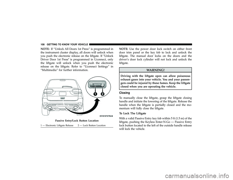
NOTE:If “Unlock All Doors 1st Press” is programmed in
the instrument cluster display, all doors will unlock when
you push the electronic release on the liftgate. If �Unlock
Driver Door 1st Press� is programmed in Uconnect, only
the liftgate will unlock when you push the electronic
release on the liftgate. Refer to “Uconnect Settings” in
“Multimedia” for further information. NOTE:
Use the power door lock switch on either front
door trim panel or the key fob to lock and unlock the
liftgate. The manual door locks on the doors and the
driver’s door lock cylinder will not lock and unlock the
liftgate.
Page 122 of 626
General Information
The following regulatory statement applies to all Radio
Frequency (RF) devices equipped in this vehicle:
This device complies with Part 15 of the FCC Rules and
with Innovation, Science and Economic Development
Canada license-exempt RSS standard(s). Operation is sub-
ject to the following two conditions:
1. This device may not cause harmful interference, and
2. This device must accept any interference received, in-cluding interference that may cause undesired opera-
tion.
NOTE: Changes or modifications not expressly approved
by the party responsible for compliance could void the
user ’s authority to operate the equipment.
INTERNAL EQUIPMENT
Storage
Glove Compartment
The glove compartment is located on the passenger side of
the instrument panel.
Page 128 of 626
CAUTION!
Power outlets are designed for accessory plugs only.
Do not insert any other object in the power outlets as
this will damage the outlet and blow the fuse. Im-
proper use of the power outlet can cause damage not
covered by your New Vehicle Limited Warranty.
The front power outlet is located inside the storage area on
the center stack of the instrument panel. Push inward on
the storage lid to open the compartment and gain access to
this power outlet.
Page 135 of 626
GETTING TO KNOW YOUR INSTRUMENT PANEL
CONTENTS
Page 138 of 626
INSTRUMENT CLUSTER DISPLAY
Your vehicle will be equipped with an instrument cluster
display, which offers useful information to the driver. With
the ignition in the STOP/OFF mode, opening/closing of a
door will activate the display for viewing, and display the
total miles, or kilometers, in the odometer. Your instrument
cluster display is designed to display important informa-
tion about your vehicle’s systems and features. Using a
driver interactive display located on the instrument panel,
your instrument cluster display can show you how sys-
tems are working and give you warnings when they are
not. The steering wheel mounted controls allow you to
scroll through the main menus and submenus. You can
access the specific information you want and make selec-
tions and adjustments.
Instrument Cluster Display Location And Controls
The instrument cluster display is located in the center of
the instrument cluster.

 devices equipped in this vehicle:
This device complies with Part 15 of the FCC Rules and
with Innovation, Sci")


