2018 SUBARU CROSSTREK fuel
[x] Cancel search: fuelPage 69 of 474
(70,1)
北米Model "A1320BE-C" EDITED: 2017/ 10/ 10
of fire caused by leaking fuel. For
details about restarting of the engine,
refer to“If your vehicle is involved in an
accident”F9-20.&General precautions regard-
ing SRS airbag system for
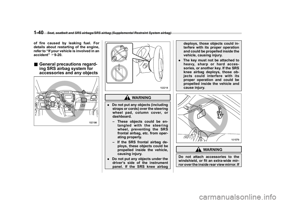
accessories and any objects
WARNING
.Do not put any objects (including
straps or cords) over the steering
wheel pad, column cover, or
dashboard.
–These objects could be en-
tangled with the steering
wheel, preventing the SRS
frontal airbag, etc. from oper-
ating properly.
–If the SRS frontal airbag de-
ploys, these objects could be
propelled inside the vehicle,
causing injury.
.Do not put any objects under the
driver’s side of the instrument
panel. If the SRS knee airbagdeploys, those objects could in-
terfere with its proper operation
and could be propelled inside the
vehicle, causing injury.
.The key must not be attached to
heavy, sharp or hard acces-
sories, or another key. If the SRS
knee airbag deploys, those ob-
jects could interfere with its
proper operation and could be
propelled inside the vehicle and
cause injury.
WARNING
Do not attach accessories to the
windshield, or fit an extra-wide mir-
ror over the inside rear view mirror. If
Seat, seatbelt and SRS airbags/SRS airbag (Supplemental Restraint System airbag)
1-40
Page 134 of 474

(139,1)
北米Model "A1320BE-C" EDITED: 2017/ 10/ 10
Ignition switch (models without“keyless
access with push-button start system”) ............ 3-4
Key positions......................................................... 3-4
Key reminder chime............................................... 3-5
Ignition switch light (if equipped)........................... 3-5
Push-button ignition switch (models with
“keyless access with push-button start
system”) ............................................................... 3-6
Safety precautions................................................. 3-6
Operating range for push-button start system........ 3-6
Switching power status.......................................... 3-7
When access key fob does not operate properly.... 3-8
Hazard warning flasher..........................................3-8
Meters and gauges.................................................3-8
Speedometer......................................................... 3-8
Tachometer............................................................ 3-8
Odometer............................................................... 3-9
Double trip meter................................................... 3-9
Fuel gauge............................................................3-10
ECO gauge (if equipped).......................................3-10
Combination meter settings.................................. 3-11
Illumination brightness control............................3-12
Auto dimmer cancel function (if equipped)............3-12
Warning andindicator..........................................3-12
Initial illumination for system check......................3-12
Seatbelt warning light and chime..........................3-13
SRS airbag system warning light...........................3-15
Front passenger’s frontal airbag ON and OFF
indicators...........................................................3-15
CHECK ENGINE warning light/Malfunction
indicator light.....................................................3-15Coolant temperature low indicator light/Coolant
temperature high warning light..........................3-16
Charge warning light............................................3-17
Oil pressure warning light.....................................3-17
Engine low oil level warning light..........................3-18
Windshield washer fluid warning light...................3-18
AT OIL TEMP warning light (CVT models)..............3-18
Low tire pressure warning light
(U.S.-spec. models)............................................3-18
ABS warning light.................................................3-20
Brake system warning light (red)..........................3-21
Low fuel warning light..........................................3-22
Hill start assist warning light/Hill start assist
OFF indicator light.............................................3-22
Door open warning light.......................................3-22
All-Wheel Drive warning light (CVT models)..........3-22
Power steering warning light ................................3-23
Vehicle Dynamics Control warning light/Vehicle
Dynamics Control operation indicator light........3-23
Vehicle Dynamics Control OFF indicator light.......3-24
Warning chimes and warning indicator of the
keyless access with push-button start system
(if equipped)......................................................3-25
Security indicator light..........................................3-29
Select lever/gear position indicator
(CVT models).....................................................3-30
Turn signal indicator lights...................................3-30
High beam indicator light......................................3-30
High beam assist indicator light (green)
(if equipped)......................................................3-30
High beam assist warning indicator (yellow)
(if equipped)......................................................3-30
Instruments and controls
3
Page 141 of 474
(146,1)
北米Model "A1320BE-C" EDITED: 2017/ 10/ 10
.If the indicator light on the push-
button ignition switch flashes in green
when the push-button ignition switch is
pressed, steering is locked. When this
occurs, press the push-button ignition
switch while turning the steering wheel
left and right.
!Battery drainage prevention func-
tion
When the push-button ignition switch is left
in the“ACC”or“ON”position for approxi-
mately 1 hour, the push-button ignition
switch will be automatically switched to
“OFF”to prevent the battery from going
dead.&When access key fob does
not operate properlyRefer to“Access key fob–if access key
fob does not operate properly”F9-17.
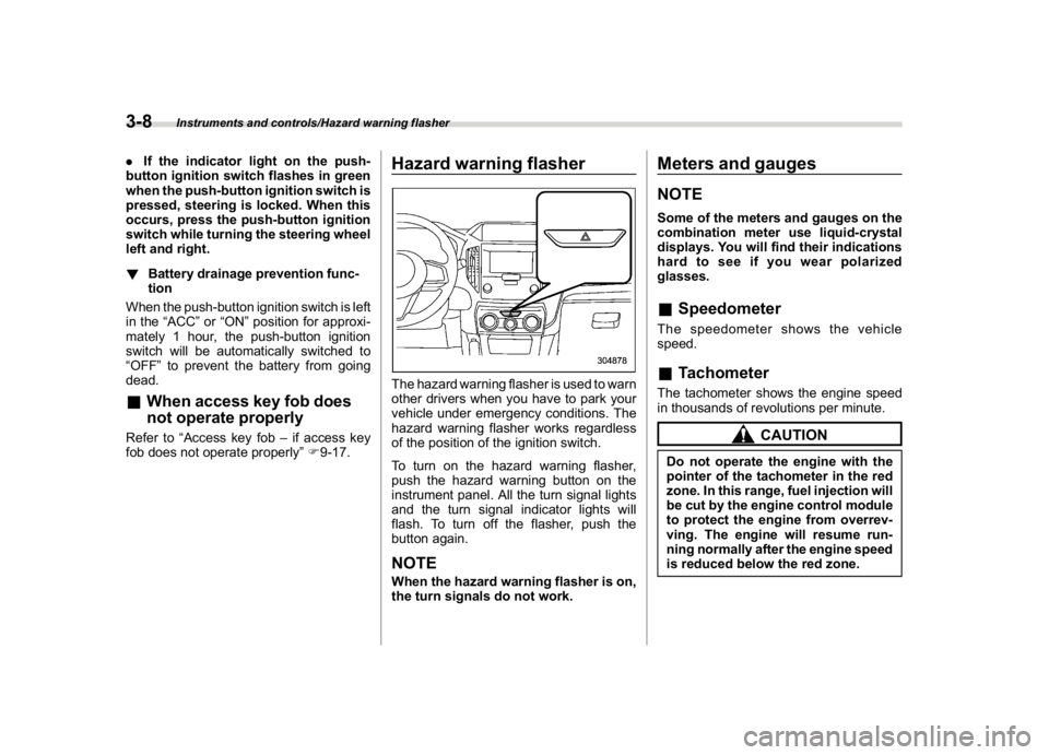
Hazard warning flasherThe hazard warning flasher is used to warn
other drivers when you have to park your
vehicle under emergency conditions. The
hazard warning flasher works regardless
of the position of the ignition switch.
To turn on the hazard warning flasher,
push the hazard warning button on the
instrument panel. All the turn signal lights
and the turn signal indicator lights will
flash. To turn off the flasher, push the
button again.NOTEWhen the hazard warning flasher is on,
the turn signals do not work.
Meters and gaugesNOTESome of the meters and gauges on the
combination meter use liquid-crystal
displays. You will find their indications
hard to see if you wear polarized
glasses.&SpeedometerThe speedometer shows the vehicle
speed.&TachometerThe tachometer shows the engine speed
in thousands of revolutions per minute.
CAUTION
Do not operate the engine with the
pointer of the tachometer in the red
zone. In this range, fuel injection will
be cut by the engine control module
to protect the engine from overrev-
ving. The engine will resume run-
ning normally after the engine speed
is reduced below the red zone.
Instruments and controls/Hazard warning flasher
3-8
Page 143 of 474
(148,1)
北米Model "A1320BE-C" EDITED: 2017/ 10/ 10
NOTE.If the connection between the com-
bination meter and battery is broken for
any reason such as vehicle mainte-
nance or fuse replacement, the data
recorded on the trip meter will be lost.
.If you press the TRIP RESET switch
when the ignition switch is in the
“LOCK”/“OFF”or“ACC”position, the
odometer/trip meter will light up. It is
possible to switch between the A trip
meter and B trip meter indications while
the odometer/trip meter is lit up.
In addition, it is possible to reset the trip
meter by pressing and holding the TRIP
RESET switch.
The indicators will turn off when:
–The TRIP RESET switch is not
operated for approximately 10 sec-
onds.
–The driver’s door is opened and
then closed.
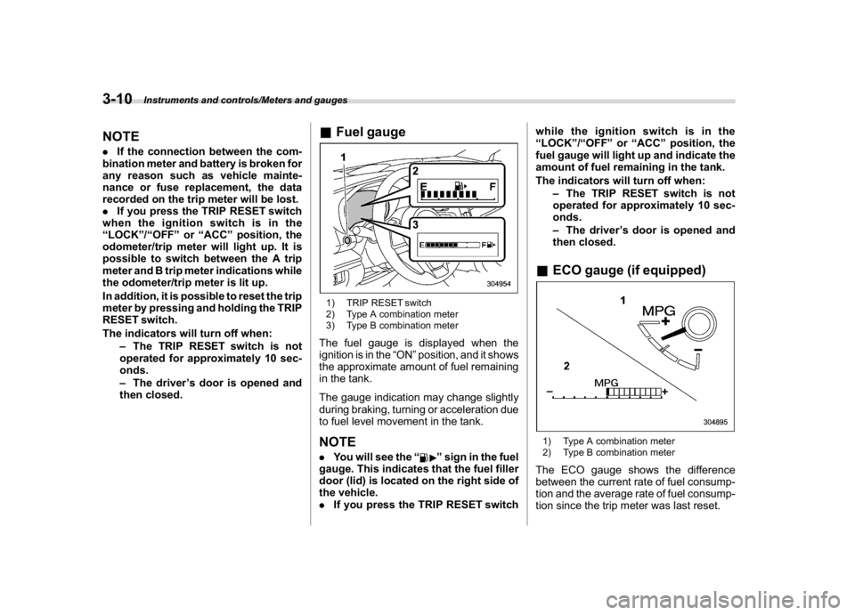
&Fuel gauge1) TRIP RESET switch
2) Type A combination meter
3) Type B combination meterThe fuel gauge is displayed when the
ignition is in the“ON”position, and it shows
the approximate amount of fuel remaining
in the tank.
The gauge indication may change slightly
during braking, turning or acceleration due
to fuel level movement in the tank.NOTE.You will see the“
”sign in the fuel
gauge. This indicates that the fuel filler
door (lid) is located on the right side of
the vehicle.
.If you press the TRIP RESET switchwhile the ignition switch is in the
“LOCK”/“OFF”or“ACC”position, the
fuel gauge will light up and indicate the
amount of fuel remaining in the tank.
The indicators will turn off when:
–The TRIP RESET switch is not
operated for approximately 10 sec-
onds.
–The driver’s door is opened and
then closed.
&ECO gauge (if equipped)1) Type A combination meter
2) Type B combination meterThe ECO gauge shows the difference
between the current rate of fuel consump-
tion and the average rate of fuel consump-
tion since the trip meter was last reset.
Instruments and controls/Meters and gauges
3-10
Page 144 of 474
(149,1)
北米Model "A1320BE-C" EDITED: 2017/ 10/ 10
If the ECO gauge moves towards the +
side, this indicates better fuel efficiency.NOTE.The ECO gauge shows only an
approximate indication of fuel effi-
ciency.
.After resetting the trip meter, the
average rate of fuel consumption is not
shown until you have driven for 1 mile
(or 1 km). Before that time, the ECO
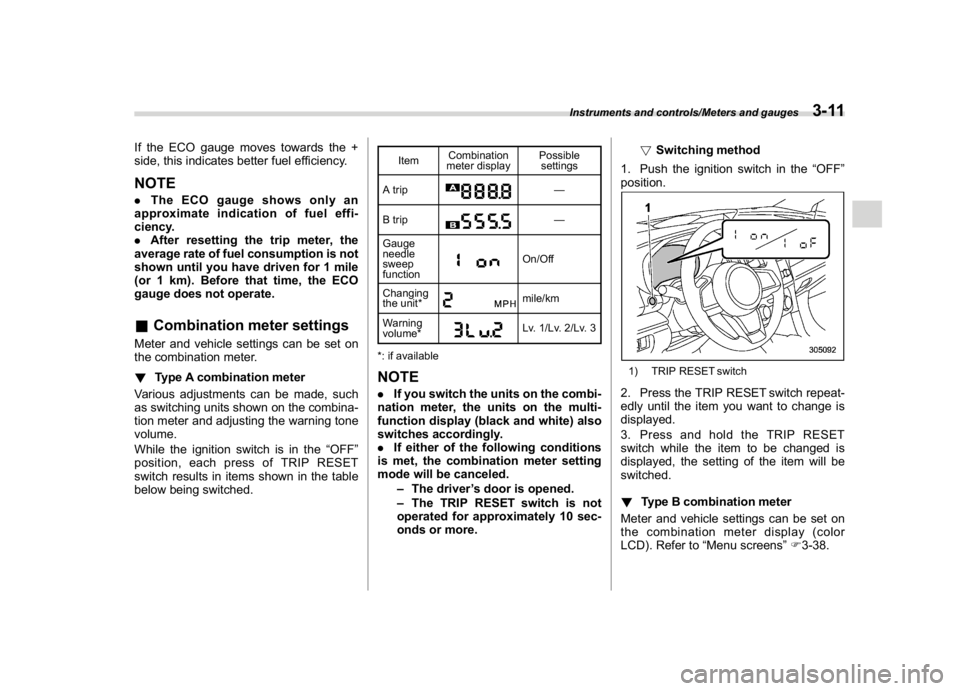
gauge does not operate.&Combination meter settingsMeter and vehicle settings can be set on
the combination meter.
!Type A combination meter
Various adjustments can be made, such
as switching units shown on the combina-
tion meter and adjusting the warning tone
volume.
While the ignition switch is in the“OFF”
position, each press of TRIP RESET
switch results in items shown in the table
below being switched.
ItemCombination
meter displayPossible
settings
A trip
—
B trip—
Gauge
needle
sweep
function
On/Off
Changing
the unit*mile/km
Warning
volume*Lv. 1/Lv. 2/Lv. 3
*: if available
NOTE.If you switch the units on the combi-
nation meter, the units on the multi-
function display (black and white) also
switches accordingly.
.If either of the following conditions
is met, the combination meter setting
mode will be canceled.
–The driver’s door is opened.
–The TRIP RESET switch is not
operated for approximately 10 sec-
onds or more.!Switching method
1. Push the ignition switch in the“OFF”
position.
1) TRIP RESET switch2. Press the TRIP RESET switch repeat-
edly until the item you want to change is
displayed.
3. Press and hold the TRIP RESET
switch while the item to be changed is
displayed, the setting of the item will be
switched.
!Type B combination meter
Meter and vehicle settings can be set on
the combination meter display (color
LCD). Refer to“Menu screens”F3-38.
Instruments and controls/Meters and gauges
3-11
3
Page 146 of 474
(151,1)
北米Model "A1320BE-C" EDITED: 2017/ 10/ 10
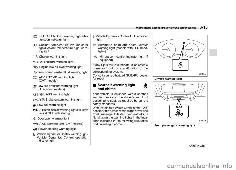
: CHECK ENGINE warning light/Mal-
function indicator light: Coolant temperature low indicator
light/Coolant temperature high warn-
ing light: Charge warning light: Oil pressure warning light: Engine low oil level warning light: Windshield washer fluid warning light: AT OIL TEMP warning light
(CVT models): Low tire pressure warning light
(U.S.- spec. models)/
: ABS warning light
/
: Brake system warning light
: Low fuel warning light: Hill start assist warning light/Hill start
assist OFF indicator light: Door open warning light: AWD warning light (CVT models): Power steering warning light: Vehicle Dynamics Control warning light/
Vehicle Dynamics Control operation
indicator light
: Vehicle Dynamics Control OFF indicator
light: Automatic headlight beam leveler
warning light (models with LED head-
lights): Hill descent control indicator light (if
equipped)
If any lights fail to illuminate, it indicates a
burned-out bulb or a malfunction of the
corresponding system.
Consult your authorized SUBARU dealer
for repair.
&Seatbelt warning light
and chimeYour vehicle is equipped with a seatbelt
warning device at the driver’s and front
passenger’s seat, as required by current
safety standards.
With the ignition switch turned to the“ON”
position, this device reminds the driver and
front passenger to fasten their seatbelts by
illuminating the warning lights in the loca-
tions indicated in the following illustration
and sounding a chime.
Driver’s warning lightFront passenger’s warning light
–CONTINUED–
Instruments and controls/Warning and indicator
3-13
3
Page 149 of 474
(154,1)
北米Model "A1320BE-C" EDITED: 2017/ 10/ 10
serious damage, which may not be
covered by your vehicle’s warranty.
If this light illuminates steadily or blinks
while the engine is running, it may indicate
that there is at least one problem or
potential problem somewhere in the emis-
sion control system.
!If the light illuminates steadily
If the light illuminates steadily while driving
or does not turn off after the engine starts,
an emission control system malfunction
has been detected.
You should have your vehicle checked by
an authorized SUBARU dealer immedi-
ately.NOTEThis light also illuminates when the fuel
filler cap is not tightened until it clicks.
If you have recently refueled your vehicle,
the cause of the CHECK ENGINE warning
light/malfunction indicator light illuminating
could be a loose or missing fuel filler cap.
Remove the cap and retighten it until it
clicks. Make sure nothing is interfering with
the sealing of the cap. Tightening the cap
will not make the CHECK ENGINE warn-
ing light turn off immediately. It may take
several driving trips. If the light does not
turn off, take your vehicle to your author-ized SUBARU dealer immediately.
!If the light is blinking
If the light is blinking while driving, an
engine misfire condition has been de-
tected which may damage the emission
control system.
To prevent serious damage to the emis-
sion control system, you should do the
following.
.Reduce vehicle speed.
.Avoid hard acceleration.
.Avoid steep uphill grades.
.Reduce the amount of cargo, if possi-
ble.
.Stop towing a trailer as soon as
possible.
The CHECK ENGINE warning light may
stop blinking and illuminate steadily after
several driving trips. You should have your
vehicle checked by an authorized
SUBARU dealer immediately.
&Coolant temperature
low indicator light/Cool-
ant temperature high
warning light
CAUTION
.After turning the ignition switch
to the“ON”position, if this
indicator light/warning light be-
haves in any of the following
ways, the electrical system may
be malfunctioning. Contact your
SUBARU dealer immediately for
an inspection.
–It remains blinking in RED.
–It remains illuminated in RED
for more than 2 seconds.
–It remains blinking in RED and
BLUE alternately.
.While driving, if this indicator
light/warning light behaves in
any of the following ways, take
the specified appropriate mea-
sure listed below.
–Blinking or illuminated in
RED:
Safely stop the vehicle as
soon as possible, and refer to
the emergency steps to take in
the case of engine overheat-
Instruments and controls/Warning and indicator
3-16
Page 152 of 474

(157,1)
北米Model "A1320BE-C" EDITED: 2017/ 10/ 10
inflated to the inflation pressure recom-
mended by the vehicle manufacturer on
the vehicle placard or tire inflation pres-
sure label. (If your vehicle has tires of a
different size than the size indicated on the
vehicle placard or tire inflation pressure
label, you should determine the proper tire
inflation pressure for those tires.)
As an added safety feature, your vehicle
has been equipped with a tire pressure
monitoring system (TPMS) that illuminates
a low tire pressure telltale when one or
more of your tires is significantly under-
inflated. Accordingly, when the low tire
pressure telltale illuminates, you should
stop and check your tires as soon as
possible, and inflate them to the proper
pressure. Driving on a significantly under-
inflated tire causes the tire to overheat and
can lead to tire failure. Under-inflation also
reduces fuel efficiency and tire tread life,
and may affect the vehicle’s handling and
stopping ability.
Please note that the TPMS is not a
substitute for proper tire maintenance,
and it is the driver’s responsibility to
maintain correct tire pressure, even if
under-inflation has not reached the level
to trigger illumination of the TPMS low tire
pressure telltale.
Your vehicle has also been equipped with
a TPMS malfunction indicator to indicatewhen the system is not operating properly.
The TPMS malfunction indicator is com-
bined with the low tire pressure telltale.
When the system detects a malfunction,
the telltale will flash for approximately one
minute and then remain continuously
illuminated. This sequence will continue
upon subsequent vehicle start-ups as long
as the malfunction exists. When the mal-
function indicator is illuminated, the sys-
tem may not be able to detect or signal low
tire pressure as intended. TPMS malfunc-
tions may occur for a variety of reasons,
including the installation of replacement or
alternate tires or wheels on the vehicle that
prevent the TPMS from functioning prop-
erly. Always check the TPMS malfunction
telltale after replacing one or more tires or
wheels on your vehicle to ensure that the
replacement or alternate tires and wheels
allow the TPMS to continue to function
properly.
Should the warning light illuminate steadily
after blinking for approximately one min-
ute, have the system inspected by your
nearest SUBARU dealer as soon as
possible.
WARNING
If this light does not illuminate
briefly after the ignition switch is
turned ON or the light illuminates
steadily after blinking for approxi-
mately one minute, you should have
your Tire Pressure Monitoring Sys-
tem checked at a SUBARU dealer as
soon as possible.
If this light illuminates while driving,
never brake suddenly and keep
driving straight ahead while gradu-
ally reducing speed. Then slowly
pull off the road to a safe place.
Otherwise an accident involving
serious vehicle damage and serious
personal injury could occur.
If this light still illuminates while
driving after adjusting the tire pres-
sure, a tire may have significant
damage and a fast leak that causes
the tire to lose air rapidly. If you have
a flat tire, replace it with a spare tire
as soon as possible.
When a spare tire is mounted or a
wheel rim is replaced without the
original pressure sensor/transmitter
being transferred, the Low tire pres-
sure warning light will illuminate
steadily after blinking for approxi-
mately one minute. This indicates
–CONTINUED–
Instruments and controls/Warning and indicator
3-19
3