Page 249 of 348

Driver assistance systems
signs in front of the vehicle. After checking
and ev aluatin
g the inf
ormation from the cam-
era, the navigation system and the current
vehicle data, up to three valid traffic signs
are displayed ››› Fig. 214 B in conjunction
with their corresponding additional signs.
The sign that is currently valid for the
driver is shown in the left side of the
screen For example, a maximum speed
limit of 130 km/h (100 mph)
››› Fig. 214 A.
A sign valid only in certain circum-
stances, e.g. 100 km/h (60 mph) is
shown second, together with the addi-
tional rain sign.
If the windscreen wiper is
working while you are driving, the signal
with the additional rain sign will be
shown first, on the left, as it is the one
that is applicable at the time.
A sign valid only with restrictions, e.g.
No overtaking at certain times, will be
displayed third ››› Fig. 214 C.
Speed warning
If the system detects that the permitted
speed is exceeded, it may warn the driver
with a “gong” and visually with a message
on the dash panel display.
The speed warning can be adjusted or deacti-
vated completely in the infotainment system
using the button and the
S
ET
TINGS and
First:
Second:
Additional sign:
Third:
Driver Assistance function buttons
› ›
›
page 33. The speed is adjusted in
steps of 5 km/h (3 mph) within a range of be-
tween 0 km/h (mph) and 20 km/h (12 mph)
above the maximum speed permitted.
Trailer mode
In vehicles equipped with a towing bracket
device from the factory and a trailer that is
electrically connected to the vehicle, it is pos-
sible to activate or deactivate the display of
specific traffic signs for vehicles with trailer,
such as speed limits or overtaking prohibi-
tions. Activation or deactivation is performed
on the infotainment system using the button and the
S
ET
TINGS and
Driv er As
s
istance function buttons
› ›
›
page 33.
For trailer mode, the display of speed limits
applicable to the type of trailer or to the legal
provisions can be adjusted. The speed is ad-
justed in steps of 10 km/h (5 mph) within a
range of between 60 km/h (40 mph) and
130 km/h (80 mph). If it is adjusted to a
speed greater than that which is permitted in
the country in question for driving with a
trailer, the system automatically displays the
usual speed limits, e.g. in Germany 80 km/h
(50 mph).
If the speed warning for the trailer is deacti-
vated, the system displays the speed limits
as if there were no trailer hitched. Limited operation
The traffic s
ign detection system has certain
limitations. The following cases may lead the
system to operate with limitations or not at
all:
● In the case of poor visibility, e.g. in snow,
rain, fog or int
ense mist.
● In cases of dazzling, e.g. caused by head-
on traffic or b
y the sun.
● When driving at high speeds.
● If the camera is covered or dirty.
● If the traffic signs are out of the camera's
field of
vision.
● If the traffic signs are partially or totally
cov
ered, e.g. by trees, snow, dirt or other ve-
hicles.
● In the case of traffic signs that do not fulfil
the regu
lations.
● In the case of damaged or bent traffic
signs.
● In the c
ase of variable messages on over-
head or g
antry signs (LED-based variable traf-
fic signs or other lighting units).
● If the maps on the navigation system are
not up-to-d
ate.
● In the case of adhesives affixed to vehicles
that depict
traffic signs, e.g. speed limits on
lorries.
247
Technical data
Advice
Operation
Emergencies
Safety
Page 250 of 348

Operation
Fatigue detection (break rec-
ommend ation)*
Intr oduction The Fatigue detection informs the driver
when their drivin
g beh
aviour shows signs of
fatigue. WARNING
Do not let the comfort afforded by the Fatigue
detection sy s
tem tempt you into taking any
risks when driving. Take regular breaks, suffi-
cient in length when making long journeys.
● The driver always assumes the responsibil-
ity of driv
ing to their full capacity.
● Never drive if you are tired.
● The system does not detect the tiredness of
the driver in al
l circumstances. Consult the in-
formation in the section ››› page 248, System
limitations.
● In some situations, the system may incor-
rectly int
erpret an intended driving manoeu-
vre as driver tiredness.
● No warning is given in the event of the ef-
fect c
alled microsleep!
● Please observe the indications on the in-
strument p
anel and act as is necessary. Note
● Fatigue det ection h
as been developed for
driving on motorways and well paved roads
only.
● If there is a fault in the system, have it
check
ed by a specialised workshop. Function and operation
Fig. 215
On the instrument panel display: fa-
tigue det ection symbo
l
. Fatigue detection determines the driving be-
h
av
iour of
the driver when starting a journey,
making a calculation of tiredness. This is
constantly compared with the current driving
behaviour. If the system detects that the driv-
er is tired, an audible warning is given with a
sound and an optic warning is shown with a
symbol and complementary message on the
instrument panel display ››› Fig. 215. The
message on the instrument panel display is shown for approximately 5 seconds, and de-
pending on the ca
se, is repeated. The system
stores the last message displayed.
The message on the instrument panel display
can be switched off by pressing the button on the windscreen wiper lever or the
b
utt
on on the multi function steering
wheel
›
›
› page 36.
The message can be recalled to the instru-
ment panel display using the multifunction
display ›››
page 36.
Conditions of operation
Driving behaviour is only calculated on
speeds above about 65 km/h (40 mph) up to
around 200 km/h (125 mph).
Switching on and off
Fatigue detection can be activated or deacti-
vated in the Easy Connect system with the button and the
S
ET
TINGS function button
› ›
›
page 33. A mark indicates that the ad-
justment has been activated.
System limitations
The Fatigue detection has certain limitations
inherent to the system. The following condi-
tions can limit the Fatigue detection or pre-
vent it from functioning.
● At speeds below 65 km/h (40 mph)
● At speeds above 200 km/h (125 mph)
248
Page 251 of 348

Driver assistance systems
● When c ornerin
g
● On r
oads in poor condition
● In unfavourable weather conditions
● When a sporty driving style is employed
● In the event of a serious distraction to the
driver
Fatigue det
ection will be restored when the
vehicle is stopped for more than 15 minutes,
when the ignition is switched off or when the
driver has unbuckled their seat belt and
opened the door.
In the event of slow driving during a long pe-
riod of time (below 65 km/h, 40 mph) the
system automatically re-establishes the tired-
ness calculation. When driving at a faster
speed the driving behaviour will be recalcula-
ted.
Park Assist*
Relat
ed video Fig. 216
Smart solutions Introduction
The Park Assist system is an additional func-
tion of P
arkPi
lot ››› page 257 and helps the
driver to:
● find a suitable parking space,
● select a parking mode,
● park driving in reverse in suitable perpen-
dicul
ar and parallel spaces,
● park driving forwards in suitable perpen-
dicul
ar spaces,
● exit a parking space driving forwards from
a par al
lel space.
In vehicles with a Park Assist system and fac-
tory radio the front, rear and side areas are
represented, and the position of obstacles is
shown relative to the vehicle.
The Park Assist system is subject to certain
limitations inherent to the system and its use
requires special attention by the driver ››› .
WARNING
The technology used in the park assist sys-
tem in v
olves a series of limitations inherent
in the actual system and in the use of ultra-
sonic sensors. The use of Park Assist should
never tempt you to take any risk that may
compromise safety. The system is not a re-
placement for driver awareness.
● Any accidental movement of the vehicle
coul
d result in serious injury. ●
Adapt
your speed and driving style at all
times to suit visibility, weather, road and traf-
fic conditions.
● Certain surfaces of objects and garments
do not refl
ect the ultrasound sensors' sig-
nals. The system cannot detect, at least cor-
rectly, these objects or people wearing such
clothes.
● Ultrasound sensor signals may be affected
by e
xternal sound sources. In certain circum-
stances this may prevent them from detect-
ing people or objects.
● The ultrasound sensors have blind spots in
which ob
stacles and people are not regis-
tered.
● Monitor the area around the vehicle at all
times, sinc
e the ultrasound sensors do not
detect small children, animals or certain ob-
jects in all situations. WARNING
Quick turns of the steering wheel when park-
ing or e x
iting a parking space with Park As-
sist can cause serious injury.
● Do not hold the steering wheel during ma-
noeuvre
s to park or exit a parking space until
the system requests it. Doing so disables the
system during the manoeuvre, resulting in
the parking being cancelled. » 249
Technical data
Advice
Operation
Emergencies
Safety
Page 252 of 348

Operation
CAUTION
● In cer t
ain circumstances, the ultrasonic
sensors do not detect objects such as trailer
tongues, bars, fences, posts or thin trees, or
an open (or opening) rear lid, which could
damage the vehicle.
● Retrofitting of certain accessories to the ve-
hicle, s
uch as a bicycle rack, may interfere
with the operation of the Park Assist system
and cause damage.
● The Park Assist system uses as a reference
parked
vehicles, curbs and other objects.
Make sure that the tyres and wheels are not
damaged while parking. If necessary, oppor-
tunely interrupt the parking manoeuvre to
avoid damaging the vehicle.
● The ultrasound sensors on the bumper may
be damag
ed or shifted in the event of a colli-
sion, for example, when entering or exiting a
parking space.
● If you use high-pressure or vapour equip-
ment to c
lean the ultrasound sensors, do not
apply it directly unless very briefly and al-
ways from a distance of more than 10 cm.
● A registration plate or plate holder on the
front w
ith larger than the space for the regis-
tration plate, or a registration plate that is
curved or warped can cause:
–false detections,
– loss of sensor visibility.
– cancellation of the parking manoeuvre or
defective parking. ●
If one of the u
ltrasonic sensors is damaged,
the area corresponding to that group of sen-
sors (front or rear) is deactivated and cannot
be activated until the fault is corrected. How-
ever, you can still use the sensors of the oth-
er bumper as per usual. If there is a fault in
the system, consult a specialist workshop.
SEAT recommends visiting a SEAT dealership
for this. Note
● In or der t o guar
antee good system opera-
tion, keep the ultrasound sensors of the
bumper clean, free of snow or ice, and do not
cover them with adhesives or other objects.
● Certain sources of noise, such as rough as-
phalt
or paving stones and the noise of other
vehicles can induce the Park Assist system or
ParkPilot to give erroneous warnings.
● In order to become familiar with the system
and its f
unctions, SEAT recommends that you
practice operating the Park Assist system in
an area where there is not too much traffic or
in a car park. Description of the Park Assist system
Fig. 217
At the top of the centre console: but-
t on t
o sw
itch on the Park Assist system. The components of the Park Assist system
ar
e the u
ltr
asonic sensors located in the front
and rear bumpers, the button ›››
Fig. 217
to switch the system on and off and the mes-
sages on the instrument panel display.
Prematurely stopping or automatically inter-
rupting the manoeuvres for parking or exit-
ing a parking space
Park Assist interrupts the manoeuvres for
parking or exiting a parking space in any of
the following cases:
● Press the
button.
● The s
peed exceeds approximately 7 km/h
(4 mph).
● The driver takes hold of the steering wheel.
250
Page 253 of 348

Driver assistance systems
● The p ark
in
g manoeuvre does not end with-
in approximately 6 minutes following activa-
tion of the automatic steering.
● There is a fault in the system (the system is
temporari
ly unavailable).
● ASR is switched off.
● ASR or ESC intervene with regulation.
● The driver door is opened.
To re
start the manoeuvre it is necessary that
none of these things occur and that the
button is pressed again.
Special Characteristics
The Park Assist system is subject to certain
limitations inherent to the system. For exam-
ple, it is therefore not possible to enter or exit
a parking space on sharp bends. While entering or exiting a parking space, a
brief sign
al sounds to prompt the driver to
change between forward and reverse gears
(depending on the case). In successive ma-
noeuvres, the assistant tells the driver to
change gears, at the latest, when the contin-
uous audible signal is given (object present
at a distance of ≤30 cm) by Park Pilot.
When the Park Assist system turns the steer-
ing wheel with the vehicle stationary, the in-
strument panel also displays the symbol .
Keep the brake pedal depressed while the
symbol remains on the dash panel display to
turn the wheels with the vehicle stopped.
This way, the system will require fewer ma-
noeuvres to complete the parking action. Trailer mode
The Park As
sist system cannot be switched
on if the factory-fitted towing bracket
››› page 273 is electrically connected to a
trailer.
After changing a wheel
If, after changing a wheel, the vehicle stops
entering and exiting parking spaces correctly,
the circumference of the new wheel may be
different and the system may need to adapt
to it. The adaptation is automatic and takes
place during driving. Making turns slowly and
in both directions (20 km/h [12 mph]) for a
few minutes may contribute to this adapta-
tion process ››› in Introduction on
p ag
e 249
.
251
Technical data
Advice
Operation
Emergencies
Safety
Page 254 of 348

Operation
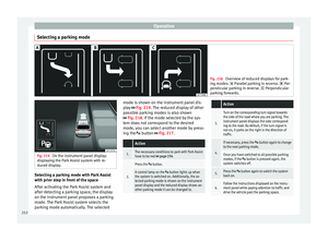
Selecting a parking mode Fig. 218
Overview of reduced displays for park-
ing mode s:
Parallel parking in reverse. Per-
pendicular parking in reverse. Perpendicular
parking forwards. Fig. 219
On the instrument panel display:
dis p
laying the Park Assist system with re-
duced display. Selecting a parking mode with Park Assist
w
ith prior s
t
ep in front of the space
After activating the Park Assist system and
after detecting a parking space, the display
on the instrument panel proposes a parking
mode. The Park Assist system selects the
parking mode automatically. The selected mode is shown on the instrument panel dis-
pla
y ››› Fig. 219. The reduced display of other
possible parking modes is also shown
››› Fig. 218. If the mode selected by the sys-
tem does not correspond to the desired
mode, you can select another mode by press-
ing the button ››› Fig. 217.
Action
1.The necessary conditions to park with Park Assist
have to be met ››› page 254.
2.
Press the button.
A control lamp on the button lights up when
the system is switched on. Additionally, the se-
lected parking mode is shown on the instrument
panel display and the reduced display shows an-
other parking mode it can be changed to.
Action
3.
Turn on the corresponding turn signal towards
the side of the road where you are parking. The
instrument panel displays the side correspond-
ing to the road. By default, if the turn signal is
not on, it parks on the right in the direction of
traffic.
4.
If necessary, press the button again to change
to the next parking mode.
Once you have switched to all possible parking
modes, if the button is pressed again, the
system switches off.
5.Press the button again to switch the system
back on.
6.Follow the instructions displayed on the instru-
ment panel while paying attention to traffic and
drive the vehicle past the parking space. 252
Page 255 of 348
Driver assistance systems
Special case of perpendicular parking space
t o p
ark
forwards without driving past first
Action
1.The necessary conditions to park with Park Assist
have to be met ››› page 254.
2.Drive forward towards the parking space while
paying attention to traffic and stop the vehicle.
Action
3.
Press the button once.
A control lamp on the button lights up when
the system is switched on. Additionally, the se-
lected parking mode is shown on the instrument
panel display without reduced display.
4.Release the steering wheel ››› in Introduction
on page 249. 253
Technical data
Advice
Operation
Emergencies
Safety
Page 256 of 348
Operation
Park with Park Assist Fig. 220
On the instrument panel display: paral-
lel p
arking. Finding a parking space. Park-
ing position. Manoeuvring. Fig. 221
On the instrument panel display: per-
pendicu l
ar parking. Finding a parking space.
Parking position. Manoeuvring. Key to
Fig. 220 and Fig. 221:
M e
s
sage to move forwards
Your vehicle
Parked vehicle
Parking space detected
Message to park
Message to press the brake pedal
Progress bar
1 2
3
4
5
6
7 Progress bars
The pr
ogr
e
ss bar
››› Fig. 220 7 and
›››
Fig. 221 7 on the
s c
r
een of the instrument panel displays the
relative distance to be covered. The greater
the distance, the fuller the progress bar.
When driving forward, the content of the pro-
gress bar decreases upwards, and when re-
versing, it decreases downwards. Necessary conditions to park with Park As-
sis
t
For parallel parking spacesFor perpendicularparking spaces
The traction control system (ASR) must be turned on ››› page 191. 254