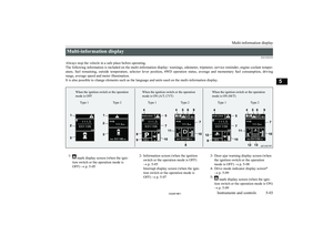
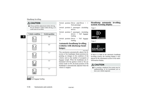
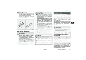
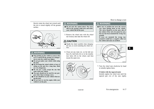
Page 345 of 514

Petrol-powered vehicles1600 modelsDiesel-powered vehicles
7.Connect one end of the other jumper ca-
ble to the negative (-) terminal of the
booster battery, and the other end to the engine block of the vehicle with the dis-
charged battery at the point farthest from the battery.
WARNINGl Make sure you observe the following or-
der when connecting the cables:
l Make sure you make connection to the
correct designated location (as shown in the illustration). If the connection is made
directly to the negative (-) side of the bat- tery, flammable gases generated from the
battery might catch fire and explode.
l When connecting the jumper cables, do
not allow the positive (+) cable and nega-
tive (-) terminal to make contact. Other- wise sparks might cause explosion of the battery.
CAUTIONl Take care not to get the jumper cable caught
in the cooling fan or other rotating part in
the engine compartment.
l Use the proper cables suitable for the battery
size to prevent overheating of the cables.
l Check the jumper cables for damage and
corrosion before use.
8. Start the engine in the vehicle which has
the booster battery, let the engine idle a
few minutes, then start the engine in the vehicle with the discharged battery.
Emergency starting
8-03OGAE18E1For emergencies82000 models 1600 models 2200 models
Page 346 of 514

CAUTIONlKeep the engine of the vehicle giving assis-
tance running.NOTEl For vehicles equipped with the Auto Stop &
Go (AS&G) system, press the “AS&G OFF”switch to deactivate the AS&G system and
prevent the engine from automatically stop- ping before the battery is sufficiently charg-
ed.
Refer to “To deactivate” on page 6-22.
9. After the engine is started, disconnect
the cables in the reverse order and keep the engine running for several minutes.
WARNINGl If the battery has to be charged while fit-
ted in the vehicle, disconnect the vehicle side negative (-) terminal connected to the
battery.
l Keep sparks, cigarettes and flames away
from the battery because the battery may produce an explosion.
l Use adequate ventilation when charging
or using the battery in an enclosed space.
l Remove all the caps before charging the
battery.WARNINGl Electrolyte is corrosive diluted sulphuric
acid.
If electrolyte (battery acid) comes into contact with your hands, eyes, clothes and
the painted surface of your vehicle, it should be thoroughly flushed with water.If electrolyte gets in your eyes, flush them
with water immediately and thoroughly, and get prompt medical attention.NOTEl If the vehicle is put in motion without fully
charging the battery, it might cause the loss
of smooth engine operation and the anti-lock brake warning lamp to illuminate.
Refer to “Anti-lock brake system (ABS)” on
page 6-48.Engine overheating
E00800604090
When the engine is overheating, the informa-tion screen in the multi-information display
will be interrupted and the engine coolant
temperature warning display will appear. Al- so “
” will blink.
If this occurs, take the following corrective measures: 1. Stop the vehicle in a safe place.
2. Check whether steam is coming from the
engine compartment.
[If steam does not come from the engine
compartment]
With the engine still running, raise the
bonnet to ventilate the engine compart-
ment.NOTEl For vehicles equipped with the Auto Stop &
Go (AS&G) system, press the “AS&G OFF”switch to deactivate the AS&G system be-
fore stopping the vehicle.
Refer to “To deactivate” on page 6-22.
[If steam is coming from the engine
compartment]
Stop the engine, and when the steam
stops, raise the bonnet to ventilate the engine compartment. Restart the engine.
WARNINGl Do not open the bonnet while steam is
coming from the engine compartment. It
could cause steam or hot water to spurt out, causing burns. Hot water could spurt
out even when there is no steam coming out, and some parts will be very hot. Be
very careful when opening the bonnet.
l Be careful of hot steam, which could cause
the cap on the engine reserve tank to blow off.
Engine overheating
8-04OGAE18E1For emergencies8
Page 347 of 514
WARNINGlDo not attempt to remove the radiator
cap while the engine is hot.
3. Confirm that the cooling fans are turn-
ing. If the fans are not turning, stop the
engine immediately and have it checked.
A- Cooling fans
B- Caution label *: Front of the vehicle
WARNINGl Be careful not to get your hands or clothes
caught in the cooling fan.4. When the bar graph in the engine cool-
ant temperature warning display in the
multi-information display drops, stop the
engine.Type 1Type 2Type 1Type 2
5. Check the coolant level in the reserve
tank (C).
Engine overheating
8-05OGAE18E1For emergencies8 Except for diesel-powered vehicles 1600 models Diesel-powered 1600 models Except for diesel-powered vehicles 1600 modelsFULLLOW
Page 348 of 514

WARNINGlIf there is none, make sure that the engine
has cooled down before removing the ra-
diator cap (D), because hot steam or boil- ing water otherwise will gush from the filler port and may scald you.
6. Fill the reserve tank with coolant as nee-
ded. (Refer to the “Maintenance” sec- tion.)
CAUTIONl Do not add coolant while the engine is hot.
Suddenly adding cold coolant could damage
the engine. Wait for the engine to cool
down, then add coolant a little at a time.7. Examine the radiator hoses for coolant
leakage and the drive belt for looseness
or damage.
If there is anything wrong with the cool-
ing system or drive belt, we recommend
you to have it checked and repaired.Tool and jack
E00800902826
Storage
The tools and jack are stowed in the luggagecompartment.
The storage location of the tools and jack should be remembered in case of an emer-
gency.
1- Tools
2- Jack
1- Tools
2- Jack
Tools
E00801900627
1- Wheel nut wrench
2- Jack bar
3- Towing hook
Tool and jack
8-06OGAE18E1For emergencies8Diesel-powered 1600 modelsFULL
LOW Vehicles with spare wheel Vehicles with tyre repair kit
Page 349 of 514

Jack
E00802001811
The jack is used only for the purpose of
changing a tyre when a tyre is punctured.
NOTEl The jack is maintenance-free.
l The jack is in conformity with EC law as ap-
proximated by the Machinery Directive
2006/42/EC.
l The EC declarations of conformity are at-
tached to the section “Declaration of Con- formity” in the end of this owner’s manual.
• The business name, full address of the
manufacturer and of his authorized repre- sentative and the designation of the jack are described in the EC declaration of
conformity.Removing and storing the jack
Before removing the jack, lift up the luggage
floor board.
Tyre repair kit*
E00804501171
This kit enables emergency repair of a smallpuncture in the tread area of a tyre that has
run over a nail, screw, or similar object.
WARNINGl The tyre repair kit may not permanently
seal a punctured tyre.
l Use only the
MITSUBISHI genuine tire
repair kit. Sealant in other repair kits
may not sufficiently seal the tire puncture.
Tyre repair kit*
8-07OGAE18E1For emergencies8 Vehicles with spare wheel Vehicles with tyre repair kit
Page 350 of 514

Tyre repair kit storage
The tyre repair kit is stowed in the luggagecompartment.
1- Tyre compressor
2- Tyre sealant bottle
3- Valve insert (spare)
4- Valve remover
5- Filler hose
6- Speed restriction sticker
How to use the tyre repair kitCAUTIONl The tyre sealant can cause health damage if
swallowed. If you accidentally swallow it,
drink as much water as possible and imme-
diately consult a doctor.
l If the tyre sealant gets in your eyes or on
your skin, rinse with lots of water. If you
still sense an abnormality, consult a doctor.
l Consult a doctor immediately if any allergic
reactions occur.
l Do not allow children to touch the tyre seal-
ant.
l Do not breathe in the vapours of tyre sealant.NOTEl
The tyre sealant cannot be used in any of the
situations listed below. If any of these situa-
tions occurs, please contact a MITSUBISHI
MOTORS Authorized Service Point or an-
other specialist.
• The tyre sealant’s expiry date has passed.
(The expiry date is shown on the bottle la- bel.)NOTE
• More than one tyre is punctured.
• The puncture hole has a length or width of
4 mm or more.
• The tyre is punctured in the side wall (A),
not in the tread (B).
• The vehicle has been driven with the tyre
almost completely flat.
Tyre repair kit*
8-08OGAE18E1For emergencies8
Page 351 of 514

NOTE•The tyre has completely slipped over the
wheel rim and has come off the wheel.
• The wheel is damaged.
l Use the tyre sealant only at ambient temper-
atures of -30 °C to + 60 °C.
l Effect an emergency repair without pulling
out the object (nail, screw, etc.) that is stuck
in the tyre.
l Do not use the tyre sealant if the tyre has
been damaged by being driven when insuffi- ciently inflated (e.g. bumps, cuts, cracks etc.
on the tyre).
l Wipe tyre sealant off the paintwork immedi-
ately with a damp cloth.
l Immediately wash clothes contaminated
with tyre sealant.
l Check the tyre sealant’s expiry date regular-
ly, and be sure to purchase a new one from a
MITSUBISHI MOTORS Authorized Serv-
ice Point before the expiry date.
Before repairing a tyre, first stop your vehicle
in a safe, flat location. 1. Park the vehicle on level and stable
ground.
2. Set the parking brake firmly.
3. On vehicles with M/T, stop the engine
and move the gearshift lever to the “R”
(Reverse) position.
On vehicles with A/T or CVT, move the
selector lever to the “P” (PARK) posi- tion and stop the engine.
4. Turn on the hazard warning flashers and
set up a warning triangle, flashing signal
lamp, etc., at an adequate distance from
the vehicle, and have all your passengers
leave the vehicle.
5. Take out the tyre sealant bottle and the
compressor.
6. Take the valve cap (C) off the tyre valve
(D), then press the valve remover (E) onto the valve as illustrated. Allow all of the air in the tyre to escape.
7. Remove the valve insert (F) by turning it
anticlockwise using the valve remover (E). Put the removed valve insert in a
clean place so it does not get dirty.
CAUTIONl If there is any air left in the tyre when you
remove the valve insert, the valve insert may
fly out and injure you. Make sure the tyre
contains no air before removing the valve in- sert.
8. Shake the tyre sealant bottle well.
Tyre repair kit*
8-09OGAE18E1For emergencies8
Page 352 of 514

NOTElIn cold conditions (when the ambient tem-
perature is 0 °C or lower), thickening of the
tyre sealant can make the tyre sealant hard to squeeze out of the bottle. Warm the bottleinside the vehicle.
9. Take the cap (G) off the tyre sealant bot-
tle (H). Do not remove the seal (I).
Screw the filler hose (J) onto the bottle
(H). As you screw the filler hose onto
the bottle, the seal will break, allowing
the sealant to be used.
CAUTIONl If you shake the bottle after screwing on the
hose, sealant may spray out of the hose.
10. Press the hose onto the valve (D). Hold-
ing the sealant bottle upside-down,
squeeze it again and again to inject all of
the sealant into the tyre.NOTEl When injecting the sealant, position the
valve away from the bottom, i.e., away from
the point where the tyre touches the ground. If the valve is near the point where the tyre touches the ground, the sealant may not gointo the tyre easily.
11. After injecting the sealant, pull the hose
off the valve, remove any residual seal- ant from the valve, rim and/or tyre. Fit the valve insert (F) into the valve (D),
and screw the valve insert securely into
place using the valve remover (E).
NOTEl When removing and screwing in the valve
insert using the valve remover, turn the valve remover by hand. Using a tool to turn the valve remover could damage it.
Tyre repair kit*
8-10OGAE18E1For emergencies8