Page 385 of 514

2.Remove the clips (C), and then remove
the air duct (D).
To install
1. Install the air duct (A), and then tighten
the clips (B).
2. Turn the upper cover over. Squeeze the
head of the moulding clip (C) with pliers and remove the moulding.
3. Install the upper cover, and then attach
the moulding (D).
NOTEl Attach the moulding with the wide part to-
wards the front of the vehicle.4. Install the clips (E).During cold weather
E01010900068
The capacity of the battery is reduced at low
temperatures. This is an inevitable result of
its chemical and physical properties.
This is why a very cold battery, particularly one that is not fully charged, will only deliver a fraction of the starter current which is nor-
mally available.
We recommend you to have the battery checked before the start of cold weather and,
if necessary, have it charged or replaced.
This does not only ensure reliable starting, but a battery which is kept fully charged alsohas a longer life.
Battery
10-11OGAE18E1Maintenance10
Page 386 of 514

Disconnection and connection
E01011001223
To disconnect the battery cable, stop the en-
gine, first disconnect the negative (-) terminal
and then the positive (+) terminal. When con-
necting the battery, first connect the positive
(+) terminal and then the negative (-) termi-
nal.
NOTEl Open the terminal cover (A) before discon-
necting or connecting the positive (+) termi-
nal of the battery.
l Loosen the nut (B), and then disconnect the
battery cable from the positive (+) terminal.NOTEWARNINGl Keep sparks, cigarettes, and flames away
from the battery because the battery could explode.
l The battery electrolyte is extremely caus-
tic. Do not allow it to come in contact with your eyes, skin, clothing, or the painted
surfaces of the vehicle.
Spilt electrolyte should be flushed imme-
diately with ample amounts of water.
Irritation to eyes or skin from contact with electrolyte requires immediate medi-
cal attention.
l Ventilate when charging or using the bat-
tery in an enclosed space.CAUTIONl Keep it out of reach of children.CAUTIONlNever disconnect the battery with the igni-
tion switch or the operation mode in ON.
Doing so could damage electric components.
l Never short-circuit the battery. This could
cause it to overheat and be damaged.
l If the battery is to be quick-charged, first
disconnect the battery cables.
l In order to prevent a short circuit, be sure to
disconnect the negative (-) terminal first.
l Always wear protective eye goggles when
working near the battery.
l Do not bring the nearby parts, the plastic
parts and so on into contact with sulphuric acid (battery electrolyte) which may crack,
stain or discolour them.
If they are in contact, wipe off with soft cloth, chamois or the like and an aqueous
solution of neutral detergent then immedi- ately rinse the affected parts with plenty of
water.NOTEl Keep the terminals clean. After the battery is
connected, apply terminal protection grease.
To clean the terminals, use lukewarm water.
l Check to see if the battery is securely instal-
led and cannot be moved during travel. Also check each terminal for tightness.
Battery
10-12OGAE18E1Maintenance10 Petrol-powered vehicles Diesel-powered vehicles
Page 387 of 514

NOTElWhen the vehicle is to be left unused for a
long period of time, remove the battery and
store it in a place where the battery fluid will not freeze. The battery should be stored only in a fully charged condition.Tyres
E01001300255WARNINGlDriving with tyres that are worn, dam-
aged or improperly inflated can lead to a
loss of control or blow out of the tyres which can result in a collision with serious
or fatal injury.Tyre inflation pressures
E01001404371ItemTyre sizeFrontRearAt trailer towingFrontRear
Normal tyre
215/65R16 98H2.4 bar (35 psi) [240 kPa] *1
,
2.6 bar (38 psi) [260 kPa]2.4 bar (35 psi) [240 kPa] *1
,
2.6 bar (38 psi) [260 kPa]215/70R16 100H2.6 bar (38 psi) [260 kPa]2.6 bar (38 psi) [260 kPa]215/60R17 96H2.2 bar (32 psi) [220 kPa]2.2 bar (32 psi) [220 kPa]225/55R18 98V2.2 bar (32 psi) [220 kPa]2.2 bar (32 psi) [220 kPa]P225/55R18 97H2.2 bar (32 psi) [220 kPa],
2.3 bar (33 psi) [230 kPa] *22.2 bar (32 psi) [220 kPa],
2.3 bar (33 psi) [230 kPa] *2
Temporary spare tyre
T155/90D164.2 bar (60 psi) [420 kPa]—215/65R162.4 bar (35 psi) [240 kPa]—215/70R162.6 bar (38 psi) [260 kPa]—*1
: Vehicles for Russia, Kazakhstan, Moldova and Ukraine
*2 : Vehicles for Russia, Kazakhstan, Moldova, Ukraine and 2200 models
Tyres
10-13OGAE18E1Maintenance10
Page 388 of 514

Check the tyre inflation pressure of all the tyres while they are cold; if insufficient or excessive, adjust to the specified value.
After the tyre inflation pressure has been adjusted, check the tyres for damage and air leaks. Be sure to put caps on the valves.
Wheel condition
E01001800885
1- Location of the tread wear indicator
2- Tread wear indicator
Check the tyres for cuts, cracks and other damage. Replace the tyres if there are deep
cuts or cracks. Also check each tyre for pieces of metal or pebbles.
The use of worn tyres can be very dangerous
because of the greater chance of skidding or
hydroplaning. The tread depth of the tyres
must exceed 1.6 mm in order for the tyres to meet the minimum requirement for use.
Tread wear indicators will appear on the sur-
face of the tyre as the tyre wears, thereby in-
dicating that the tyre no longer meets the
minimum requirement for use. When these wear indicators appear, the tyres must be re-
placed with new ones.
On 4-wheel drive vehicles, when replacement of any of the tyres is necessary, replace all of
them.CAUTIONl Always use tyres of the same size, same
type, and same brand, and which have no wear differences.
Using tyres of different size, type, brands or degree of wear, will increase the differential
oil temperature, resulting in possible damage
to the driving system. Further, the drive train will be subjected to excessive loading, possi-bly leading to oil leakage, component seiz-ure, or other serious faults.Replacing tyres and wheels
E01007201514
CAUTIONl Avoid using different size tyres from the one
listed and the combined use of different
types of tyres, as this can affect driving safe- ty.
Refer to “Tyres and wheels” on page
11-12.
l Even if a wheel has the same rim size and
offset as the specified type of wheel, its
shape may prevent it from being fitted cor- rectly. We recommend you to consult a spe-
cialist before using wheels that you have.
l As your vehicle is equipped with a tyre pres-
sure monitoring system, only MITSUBISHI
MOTORS genuine wheels should be used.
Use of another type of wheel risks air leaks and sensor damage, as it will not be possible
to install the tyre inflation pressure sensors
properly.
Refer to “Tyre pressure monitoring system
(TPMS)*” on page 6-71.
Tyres
10-14OGAE18E1Maintenance10
Page 389 of 514

Tyre rotation
E01001901317
Tyre wear varies with vehicle conditions,
road surface conditions and individual driv-
er’s driving habits. To equalize the wear and help extend tyre life, it is recommended to ro-
tate the tyres immediately after discovery of abnormal wear, or whenever the wear differ-
ence between the front and rear tyres is rec-
ognizable.
When rotating tyres, check for uneven wear and damage. Abnormal wear is usually
caused by incorrect tyre pressure, improper wheel alignment, out of balance wheel, or se-vere braking. We recommend you to have it
checked to determine the cause of irregular tread wear.
*- If the spare tyre wheel differs from thestandard tyre wheel, do not perform tyre rota-
tion using a spare wheel.
CAUTIONl A temporary spare tyre can be fitted tempo-
rarily in place of a tyre that has been re-
moved during the tyre rotation. However, it must not be included in the regular tyre rota-
tion sequence.
l If the tyres have arrows (A) indicating the
correct direction of rotation, swap the front
and rear tyres on the left-hand side of the ve- hicle and the front and rear tyres on the right-hand side of the vehicle separately. Keep each tyre on its original side of the ve-
hicle. When fitting the tyres, make sure the
arrows point in the direction in which the wheels will turn when the vehicle moves forward. Any tyre whose arrow points in the
wrong direction will not perform to its full potential.Front
Tyres
10-15OGAE18E1Maintenance10Spare tyre used
Spare tyre not used
Tyres that have arrows showing rotation directionFront
Front
Front
Page 390 of 514

CAUTIONlAvoid the combined use of different types of
tyres.
Using different types of tyres can affect ve-
hicle performance and safety.Snow tyres
E01002001852
The use of snow tyres is recommended for
driving on snow and ice. To preserve driving stability, mount snow tyres of the same size and tread pattern on all 4 wheels.
A snow tyre that is worn down more than
50% is no longer appropriate to use.
Snow tyres which do not meet specifications must not be used.
CAUTIONl Observe permissible maximum speed for
your snow tyres and the legal speed limit.
l As your vehicle is equipped with a tyre pres-
sure monitoring system, only MITSUBISHI
MOTORS genuine wheels should be used.
Use of another type of wheel risks air leaks and sensor damage, as it will not be possible
to install the tyre inflation pressure sensors
properly.
Refer to “Tyre pressure monitoring system (TPMS)*” on page 6-71.NOTEl The laws and regulations concerning snow
tyres (driving speed, required use, type, etc.)
vary. Find out and follow the laws and regu- lations in the area you intend to drive.
l If flange nuts are used on your vehicle,
change to tapered nuts when steel wheels are used.Tyre chains
E01002103394
If tyre chains have to be used, ensure that
they are fitted only on the drive wheels
(front) in accordance with the manufacturer’s instructions.
On 4WD vehicles in which the driving power
is distributed preferentially to the front wheels, ensure that the tyre chains are fitted on the front.
Use only tyre chains which are designed for use with the tyres mounted on the vehicle: use of the incorrect size or type of chain
could result in damage to the vehicle body.
Contact a MITSUBISHI MOTORS Author-
ized Service Point before putting on tyre chains. The max. chain height is as follows.
Tyre sizeWheel sizeMax. chain
height [mm]215/70R16
215/65R1616 x 6 1/2 J9 mmTyre sizeWheel sizeMax. chain
height [mm]215/60R1717 x 6 1/2 J225/55R1818x7 J
When driving with tyre chains on the tyres,
do not drive faster than 50 km/h (30 mph) .
When you reach roads that are not covered in snow, immediately remove the tyre chains.
CAUTIONl Practice fitting the chains before you need
them. Don’t expect help from other people
in the cold.
l Choose a clear straight stretch of road where
you can pull over and still be seen while you are fitting the chains.
l Do not fit chains before you need them. This
will wear out your tyres and the road sur- face.
l After driving around 100-300 metres, stop
and retighten the chains.
l Drive cautiously and do not exceed 50 km/h
(30 mph).
Remember that preventing accidents is not
the purpose of tyre chains.
l When tyre chains are installed, take care that
they do not damage the disc wheel or body.
Tyres
10-16OGAE18E1Maintenance10
Page 391 of 514

CAUTIONlDo not install a tyre chain on an emergency
wheel which is compact in size. If one of thefront wheels has punctured, replace it withone of the rear wheels and install the tempo-
rary spare wheel in that place before fitting a
tyre chain.
l An aluminium wheel can be damaged by a
tyre chain while driving. When fitting a tyre
chain on an aluminium wheel, take care that any part of the chain and fitting cannot be
brought into contact with the wheel.
l Remove the wheel covers before installing a
tyre chain, otherwise they may be damaged
by the tyre chain. (See page 8-20.)
l When installing or removing the tyre chains,
take care that hands and other parts of your
body are not injured by the sharp edges of the vehicle body.NOTEl The laws and regulations concerning the use
of tyre chains vary. Always follow local laws and regulations.
In most countries, it is prohibited by law to
use tyre chains on roads without snow.Wiper blade rubber
replacement E01002600327
Windscreen wiper blades
1. Lift the wiper arm off the windscreen.
2. Pull the wiper blade until its stopper (A)
disengages from the hook (B). Pull thewiper blade further to remove it.
NOTEl Do not let the wiper arm drop onto the wind-
screen. This could damage the glass.
3. Attach the retainers (C) to a new wiper
blade.
Refer to the illustration to ensure that the
retainers are correctly aligned as you at- tach them.
4. Insert the wiper blade into the arm, start-
ing with the opposite end of the blade from the stopper. Make sure the hook(B) is fitted correctly in the grooves in
the blade.
NOTEl If a retainer is not supplied with the new
wiper blade, use the retainer from the old
blade.
Wiper blade rubber replacement
10-17OGAE18E1Maintenance10
Page 392 of 514

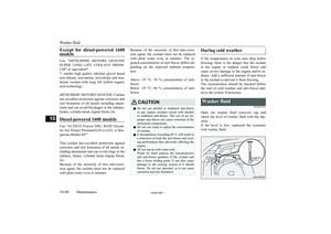
5.Push the wiper blade until the hook (B)
engages securely with the stopper (A).
Rear window wiper blades
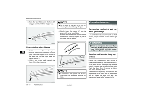
1. Lift the wiper arm off the window glass.
2. Pull the wiper blade downward to disen-
gage it from the stopper (A) at the end of
the wiper arm. Pull the wiper blade fur-
ther to remove it.
3. Slide a new wiper blade through the
hook (B) on the wiper arm.
NOTEl Do not allow the wiper arm to fall onto the
window glass; it could damage the glass.
4. Firmly insert the retainer (C) into the
groove (D) in the wiper blade.
Refer to the illustration to ensure that the retainers are correctly aligned as you in-
sert them into the groove.
NOTEl If a retainer is not supplied with the new
wiper blade, use the retainer from the old
blade.General maintenance
E01002700520
Fuel, engine coolant, oil and ex- haust gas leakage
Look under the body of your vehicle to check
for fuel, engine coolant, oil and exhaust gas
leaks.
WARNINGl If you see a suspicious fuel leak or if you
smell fuel, do not operate the vehicle; call
your MITSUBISHI MOTORS Author-
ized Service Point for assistance.
Exterior and interior lamp op-
eration
Operate the combination lamp switch to
check that all lamps are functioning properly.
If the lamps do not illuminate, the probable cause is a blown fuse or defective lamp bulb.
Check the fuses first. If there is no blown
fuse, check the lamp bulbs.
For information regarding the inspection and
replacement of the fuses and the lamp bulbs, refer to “Fuses” on page 10-19 and “Re-
placement of lamp bulbs” on page 10-26.
General maintenance
10-18OGAE18E1Maintenance10