Page 385 of 458

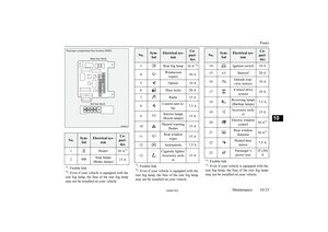
No.Sym-bolElectrical sys- temCa-
paci- ties15Headlamp high- beam (right)10 A
16
Head-lamp low
beam (left)
Dis-
charge20 A17
Head- lamp low
beam
(right)
Dis-
charge20 A18
Head- lamp low
beam (left)
Halo- gen10 A19
Head-lamp low
beam
(right)
Halo- gen10 A
20ENG/POWER10 A21Ignition coil10 A*1 : Fusible link
No.Sym-
bolElectrical sys- temCa-
paci- ties
22
ENG/POWER20 AFuel line heater25 A23Fuel pump15 A24Starter30 A *125———26Anti-lock brake
system40 A *127Anti-lock brake
system30 A *128
Air conditioning
condenser fan motor
30 A *129Radiator fan mo-
tor40 A*130IODIOD30 A31Audio system
amp30 A32Diesel30 A33—Spare fuse10 A34—Spare fuse15 A*1: Fusible link
No.Sym-
bolElectrical sys- temCa-
paci- ties35—Spare fuse20 A*1 : Fusible link
l Some fuses may not be installed on your
vehicle,  depending  on  the  vehicle  model
or specifications.
l The  table  above  shows  the  main  equip-
ment corresponding to each fuse.
The  fuse  box  does  not  contain  spare  7.5  A ,
25  A  or  30  A  fuses.  If  one  of  these  fuses burns out, substitute with the following fuse.7.5 A: 10 A spare fuse
25 A: 20 A spare fuse
30 A: 30 A audio system amp fuse
When  using  a  substitute  fuse,  replace  with  a
fuse  of  the  correct  capacity  as  soon  as  possi- ble.
Identification of fuse
CapacityColour7.5 ABrown10 ARed15 ABlue20 AYellow25 ANatural (White)
Fuses
10-25OGAE17E2Maintenance10                  


        Page 386 of 458

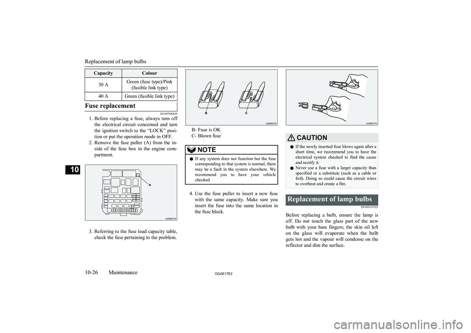
CapacityColour30 AGreen (fuse type)/Pink(fusible link type)40 AGreen (fusible link type)Fuse replacement
E01007800630
1. Before  replacing  a  fuse,  always  turn  off
the  electrical  circuit  concerned  and  turn
the  ignition  switch  to  the  “LOCK”  posi-
tion or put the operation mode in OFF.
2. Remove  the  fuse  puller  (A)  from  the  in-
side  of  the  fuse  box  in  the  engine  com-
partment.
3. Referring to the fuse load capacity table,
check the fuse pertaining to the problem.
B- Fuse is OK
C- Blown fuse
NOTEl If  any  system  does  not  function  but  the  fuse
corresponding to that system is normal, theremay  be  a  fault  in  the  system  elsewhere.  We recommend  you  to  have  your  vehiclechecked.
4. Use  the  fuse  puller  to  insert  a  new  fuse
with  the  same  capacity.  Make  sure  you
insert  the  fuse  into  the  same  location  in
the fuse block.
CAUTIONl If the newly inserted fuse blows again after a
short  time,  we  recommend  you  to  have  the electrical  system  checked  to  find  the  causeand rectify it.
l Never  use  a  fuse  with  a  larger  capacity  than
specified  or  a  substitute  (such  as  a  cable  or
foil).  Doing  so  could  cause  the  circuit  wires
to overheat and create a fire.Replacement of lamp bulbs
E01003101922
Before  replacing  a  bulb,  ensure  the  lamp  isoff.  Do  not  touch  the  glass  part  of  the  new
bulb  with  your  bare  fingers;  the  skin  oil  left
on  the  glass  will  evaporate  when  the  bulb gets  hot  and  the  vapour  will  condense  on  the
reflector and dim the surface.
Replacement of lamp bulbs
10-26OGAE17E2Maintenance10      


        Page 387 of 458

CAUTIONlBulbs  are  extremely  hot  immediately  after
being turned off.
When  replacing  a  bulb,  wait  for  it  to  cool
sufficiently  before  touching  it.  You  could otherwise be burnt.
l Do  not  install  commercially  available  LED-
type bulbs.
Commercially  available  LED-type  bulbs
could  adversely  affect  the  operation  of  the vehicle, such as by preventing the lamps andother  vehicle  equipment  from  operating
properly.NOTEl If  you  are  unsure  of  how  to  carry  out  the
work  as  required,  we  recommend  you  to consult a specialist.
l Be  careful  not  to  scratch  the  vehicle  body
when removing a lamp or lens.
l When  it  rains  or  when  the  vehicle  has  been
washed, the inside of the lens sometimes be-
comes  foggy.  This  is  the  same  phenomenon as  when  window  glass  mists  up  on  a  humid
day, and does not indicate a functional prob- lem.
When  the  lamp  is  switched  on,  the  heat  will
remove  the  fog.  However,  if  water  gathers inside  the  lamp,  we  recommend  you  to  havethe lamp checked.Bulb capacity
E01003200290
When  replacing  a  bulb,  use  a  new  bulb  with
the same wattage and colour.
Outside
E01003305023
1- Front  turn-signal  lamps:  21  W
(WY21W) 
2- Headlamps, high-beam: 60 W (HB3) 3- Type 1
Front fog lamps  *1
: 35 W (H8) 
Daytime  running  lamps  *1
:  13  W
(P13W) 
Type 2
Front fog lamps *1
: 19 W (H16)
4- Headlamps, low beam Halogen: 55 W (H11)
High intensity discharge *2
: 35 W
5- Position lamps: 5 W (W5W) 
6- Side  turn-signal  lamps  (on  fender) *1
,*2
:
5 W 
7- Side  turn-signal  lamps  (on  outside  rear-
view mirror) *1*1
:If so equipped*2:Have  the  lamps  bulbs  replaced  at  a
MITSUBISHI  MOTORS  Author-
ized Service Point.
Codes  in  parentheses  indicate  bulb
types.
WARNINGl Always  consult  a  specialist  when  repair-
ing  or  replacing  the  bulbs  of  high  intensi- ty discharge headlamps.
This  is  because  the  power  circuit,  bulbs
and  electrodes  generate  a  high  voltage that could cause an electric shock.NOTEl An LED, not a bulb, is used in the side turn-
signal lamp (on outside rear-view mirror).
Contact  a  MITSUBISHI  MOTORS  Author-
ized  Service  Point  when  there  is  a  need  for
repair or replacement.
Replacement of lamp bulbs
10-27OGAE17E2Maintenance10  Front    


        Page 388 of 458

NOTElFor  the  side  turn-signal  lamp  (on  fender),  it
is  not  possible  to  repair  or  replace  just  the
bulb.
Contact  a  MITSUBISHI  MOTORS  Author-
ized  Service  Point  when  there  is  a  need  for
repair or replacement.
8- High-mounted stop lamp 
9- Licence plate lamps: 5 W (W5W) 
10- Rear fog lamp: 21 W (W21W) 
11- Reversing lamps: 16 W (W16W) 
12- Rear turn-signal lamps: 21 W (W21W)  13- Stop and tail lamps 
Codes in parentheses indicate bulb types.
NOTEl An  LED,  not  a  bulb,  is  used  in  the  stop
lamp/tail lamp and high-mounted stop lamp.
Contact  a  MITSUBISHI  MOTORS  Author-
ized  Service  Point  when  there  is  a  need  for
repair or replacement.Inside
E01003403466
1- Room lamp (rear)*: 8 W 
2- Vanity mirror lamps*: 2 W
3- Room lamp (front) & map lamps: 8 W 
4- Luggage room lamp: 5 W
5- Glove box lamp: 1.4 W 
*: If so equipped
Headlamps (low beam, exceptfor vehicles with high intensity discharge headlamps)
E01009301522
1. When  replacing  the  bulb  on  the  left  side
of  the  vehicle  in  the  case  of  diesel-pow-
ered  vehicles,  remove  the  bolt  (A)  hold- ing down the relay box and move the re-
lay box towards the rear of the vehicle.
*: Front of the vehicle
2. When  replacing  the  bulb  on  the  right
side  of  the  vehicle  in  the  case  of  diesel-
powered  vehicles  (1600  models  only), remove  the  bolts  (B),  and  then  move  thereserve tank.
Replacement of lamp bulbs
10-28OGAE17E2Maintenance10 Rear     


        Page 389 of 458

*: Front of the vehicle
3. When  replacing  the  bulb  on  the  right
side  of  the  vehicle  in  the  case  of  diesel-
powered  vehicles,  remove  the  clips  (C)
by  prying  with  a  straight  blade  (or  mi- nus)  screwdriver,  and  remove  the  side
cover.
*: Front of the vehicle
4. Turn  the  cap  (D)  anticlockwise  to  re-
move it.
*: Front of the vehicle
5. Turn  the  bulb  (E)  anticlockwise  to  re-
move it.
*: Front of the vehicle
6. While holding down the tab (F), pull out
the socket (G).
7. To  install  the  bulb,  perform  the  removal
steps in reverse.
CAUTIONl Handle  halogen  lamp  bulbs  with  care.  The
gas inside halogen lamp bulbs is highly pres- surized, so dropping, knocking, or scratching
a halogen lamp bulb can cause it to shatter.
l Never  hold  the  halogen  lamp  bulb  with  a
bare hand, dirty glove, etc.
The oil from your hand could cause the bulb to break the next time the headlamps are op-
erated.
If  the  glass  surface  is  dirty,  it  must  be cleaned  with  alcohol,  paint  thinner,  etc.,  and
refit it after drying it thoroughly.
Replacement of lamp bulbs
10-29OGAE17E2Maintenance10       


        Page 390 of 458
Headlamps (low beam, for ve-hicles with high intensity dis- charge headlamps)
E01010100132
Do not attempt to disassemble or repair head- lamps,  and  do  not  attempt  to  replace  their
bulbs.
WARNINGl A high voltage is present in the power cir-
cuit  and  in  the  bulbs  and  bulb  terminals. To avoid the risk of an electric shock, con- tact  a  MITSUBISHI  MOTORS  Author-
ized  Service  Point  whenever  repair  or  re- placement is necessary.Headlamps (High-beam)
E01009400135
1. When  replacing  the  bulb  on  the  left  side
of  the  vehicle  in  the  case  of  diesel-pow-
ered  vehicles,  remove  the  bolt  (A)  hold-
ing down the relay box and move the re- lay box towards the rear of the vehicle.
*: Front of the vehicle
2. Turn  the  cap  (B)  anticlockwise  to  re-
move it.
*: Front of the vehicle
3. Turn  the  bulb  (C)  anticlockwise  to  re-
move it.
*: Front of the vehicle
Replacement of lamp bulbs
10-30OGAE17E2Maintenance10      


        Page 391 of 458

4.While holding down the tab (D), pull out
the socket (E).
5. To  install  the  bulb,  perform  the  removal
steps in reverse.
CAUTIONl Handle  halogen  lamp  bulbs  with  care.  The
gas inside halogen lamp bulbs is highly pres- surized, so dropping, knocking, or scratching
a halogen lamp bulb can cause it to shatter.
l Never  hold  the  halogen  lamp  bulb  with  a
bare hand, dirty glove, etc.
The oil from your hand could cause the bulb to break the next time the headlamps are op-
erated.
If  the  glass  surface  is  dirty,  it  must  be cleaned  with  alcohol,  paint  thinner,  etc.,  and
refit it after drying it thoroughly.Position lamps
E01003702589
1. When  replacing  the  bulb  on  the  left  side
of  the  vehicle  in  the  case  of  diesel-pow-
ered  vehicles,  remove  the  bolt  (A)  hold-
ing down the relay box and move the re- lay box towards the rear of the vehicle.
*: Front of the vehicle
2. When  replacing  the  bulb  on  the  right
side  of  the  vehicle  in  the  case  of  diesel-
powered  vehicles,  remove  the  clips  (B)
by  prying  with  a  straight  blade  (or  mi- nus)  screwdriver,  and  remove  the  side
cover.
*: Front of the vehicle
3. Turn  the  socket  (C)  anticlockwise  to  re-
move it.
*: Front of the vehicle
Replacement of lamp bulbs
10-31OGAE17E2Maintenance10       


        Page 392 of 458

4. Pull the bulb out of the socket.
5.To  install  the  bulb,  perform  the  removal
steps in reverse.
Front turn-signal lamps
E01003800922
To remove 1. Remove the upper cover. For  information  regarding  how  to  re-move  the  upper  cover,  refer  to  “Remov-
ing  and  installing  the  upper  cover  and duct” on page 10-10.
2. Remove  the  entire  socket  and  bulb  as-
sembly (A) by turning it anticlockwise.
*: Front of the vehicle
3. Remove the bulb by pulling it out.
To install 1. To  install  the  bulb,  perform  the  removal
steps in reverse.
2. Install the upper cover.
For  information  regarding  how  to  installthe upper cover, refer to “Removing and
installing  the  upper  cover  and  duct”  on
page 10-10.Side turn-signal lamps (on
fender)*
E01003900516
NOTEl For the side turn-signal lamps (on fender), it
is  not  possible  to  repair  or  replace  just  thebulb.
Contact  a  MITSUBISHI  MOTORS  Author-
ized  Service  Point  when  there  is  a  need  for
repair or replacement.Side turn-signal lamps (on out-
side rear-view mirror)*
E01003900529
NOTEl An LED, not a bulb, is used in the side turn-
signal lamps (on outside rear-view mirror).
Contact  a  MITSUBISHI  MOTORS  Author-
ized  Service  Point  when  there  is  a  need  for
repair or replacement.
Replacement of lamp bulbs
10-32OGAE17E2Maintenance10