Page 337 of 354

PSI (pounds per squareinch)
Astandard unit of measure for tire pressure.
Aspect ratio
Relationship between tire height and tire width
in percent.
Tire pressure
This is pressure inside the tire applying an out-
ward force to each square inch of the tire's sur-
face. The tire pressure is specified in pounds per
square inch (psi), in kilopascal (kPa) or in bar.
The tire pressure should only be corrected when
the tires are cold.
Cold tire pressure
The tires are cold:
Rif the vehicle has been parked with the tires
out of direct sunlight for at least three hours
and
Rif the vehicle has not been driven further than
1m ile (1.6 km)
Tread
The part of the tire that comes into contact with
the road.
Bead
The tire bead ensures that the tire sits securely
on the wheel. There are several steel wires in the
bead to prevent the tire from coming loose from
the wheel rim.
Sidewall
The part of the tire between the tread and the
bead.
Weight of optional extras
The combined weight of those optional extras
that weigh more than the replaced standard
parts and more than 5lbs (2.3 kg). These
optional extras, such as high-performance
brakes, level control, aroof rack or ahigh-per-
formanceb attery, are not included in the curb
weight and the weight of the accessories.
TIN (Tire Identification Number)
This is aunique identifier which can be used by
at ire manufacturer to identify tires, for example
for aproduct recall, and thus identify the pur-
chasers. The TIN is made up of the manufactur-
er's identity code, tire size, tire type code and
the manufacturing date.
Load bearing index
The load bearing index (also load index) is acode
that contains the maximum load bearing capa-
city of atire.
Traction
Traction is the result of friction between the tires
and the road surface.
Treadwear indicators
Narrow bars (tread wear bars) that are distrib-
uted over the tire tread. If the tire tread is level
with the bars, the wear limit of áin (1.6 mm)
has been reached.
Occupant distribution
The distribution of occupants in avehicle at their
designated seating positions.
Total load limit
Nominal load and luggage load plus 68 kg
(15 0lbs)m ultiplied by the number of seats in
the vehicle.
Changing awheel
Flat tire
The "Breakdown assistance" section
(Ypage 300) contains information and notes on
how to deal with aflat tire. Information on driv-
ing with MOExtended tires in the event of aflat
tire can be found under "MOExtended tires (tires
with run-flat characteristics" (
Ypage 301).
Rotating the wheels
GWARNING
Interchanging the front and rear wheels may
severely impair the driving characteristics if
the wheels or tires have different dimensions. The wheel brakes or suspension components
may also be damaged. There is arisk of acci-
dent.
Rotate front and rear wheels only if the wheels and tires are of the same dimensions.
!On vehicles equippedw ithatire pressure
monitor ,electronic components are located
in the wheel.
Changing awheel335
Wheels and tires
Z
Page 338 of 354

Tire-mounting tools should not be used near
the valve. This could damage the electronic
components.
Only have tires changed ataqualified spe-
cialist workshop.
Always observe the instructions and safety
notes in the "Mounting awheel" section
(
Ypage 336).
The wear pattern sonthe front and rear tires
differ, depending on the operating conditions.
Rotate the wheels before aclear wear pattern
has formed on the tires. Frontt ires typically
wear more on the shoulders and the rear tires in the center.
On vehicles that have the same size front and
rear wheels, you can rotatet he wheels accord-
ing to the intervals in the tire manufacturer's
warranty book in your vehicle documents. If no
warranty book is available, the tires should be
rotated every 3,000 to 6,000 miles (5,000 to
10,000k m).Earlier may be necessary, depend-
ing on the degree of tire wear. Do not change the
direction of wheel rotation.
Clean the contact surfaces of the wheel and the
brake disc thoroughly every time awheel is rota-
ted. Check the tire pressure and, if necessary,
restart the tire pressure loss warning system
(
Ypage 323) or the tire pressure monitor
(Ypage 325).
Direction of rotation
Tires with aspecified direction of rotation have
additional benefits ,e.g. if there is arisk of hydro-
planing. These advantages can only be gained if
the tires are installed corresponding to the
direction of rotation.
An arrow on the sidewall of the tire indicates its
correctd irection of rotation.
Storing wheels
Storewheels that are not being used in acool,
dry and preferably dark place. Protectt he tires
from oil, grease, gasoline and diesel.
Mounting awheel
Preparing the vehicle
XStop the vehicle on solid, non-slippery and
level ground.
XApply the electric parking brake manually.
XBring the front wheels into the straight-ahead position.
XShift the transmission to position P.
XMake sure that the vehicle level is set to "Nor-
mal" on vehicles with AIRMATIC(Ypage 172).
XSwitch off the engine.
XVehicles without KEYLESS-GO: remove the
SmartKey from the ignition lock.
XVehicles with KEYLESS-GO start-function
or KEYLESS-GO: open the driver's door.
The on-board electronics now have status 0.
This is the same as the SmartKey having been
removed.
XVehicles with KEYLESS-GO start-function
or KEYLESS-GO: remove the Start/Stop but-
ton from the ignition lock (
Ypage 131).
XMake sure that the engine cannot be started
via your smartphon e(Ypage 134).
XIf included in the vehicle equipment, remove
the tire-change tool kit from the vehicle.
XSafeguard the vehicle against rolling away.
Securing the vehicle to prevent it from
rolling away
If your vehicle is equipped with awheel chock,i t
can be found in the vehicle tool kit (Ypage 300).
The folding wheel chock is an additional safety
measure to prevent the vehicle from rolling
away,f or example when changing awheel.
336Changing awheel
Wheels and tires
Page 339 of 354

XFold both plates upwards:.
XFold outlower plate ;.
XGuide the lugs on the lower plate fully into the
openings in base plate =.
XPlace chocks or other suitabl eitems under
the front and rearoft he wheel that is diago-
nally opposite the wheel yo uwishtoc hange.
Raising the vehicle
GWARNING
If yo udon ot positio nthe jack correctly at the
appropriate jacking point of the vehicle, the
jack could tip over with the vehicle raised.
There is arisk of injury.
Only positio nthe jack at the appropriate jack-
ing point of the vehicle. The base of the jack
mus tbep ositioned vertically ,directly under
the jacking point of the vehicle.
!The jack is designe dexclusively for jacking
up the vehicle at the jacking points. Other-
wise, your vehicle could be damaged.
Observe the following whe nraising the vehi-
cle:
RTo raise the vehicle, only use the vehicle-spe-
cifi cjack that has bee ntested and approved
by Mercedes-Benz. If use dincorrectly ,the
jack could tip over with the vehicle raised.
RThe jack is designe donly to raise and hol dthe
vehicle for ashortt ime while awheel is being
changed. It mus tnot be use dfor performing
maintenance wor kunder the vehicle.
RAvoid changing the wheel on uphil land down-
hil lslopes.
RBeforer aising the vehicle, secure it from roll-
ing away by applying the parking brake and inserting wheel chocks. Do not disengage the
parking brake while the vehicle is raised.
RThe jack mus
tbep laced on afirm, fla tand
non-sli psurface .Onal oose surface ,alarge,
flat, load-bearing underlay mus tbeu sed. On a
slippery surface ,anon-sli punderlay mus tbe
used, e.g. rubber mats.
RDo not use wooden blocks or simila robjects
as ajack und erlay.Otherwise ,the jack will not
be able to achieve its load-bearing capacity
duetot he restricted height.
RMake sur ethat the distance between the
underside of the tires and the ground doe snot
excee d1.2 in (3 cm).
RNeve rplace your hand sand feet under the
raised vehicle.
RDo not li eunder the vehicle.
RDo not start the engine whe nthe vehicle is
raised.
RDo not ope norclosead oorort he trunk lid
whe nthe vehicle is raised.
RMake sur ethat no persons are present in the
vehicle whe nthe vehicle is raised.
Vehicles with alloy wheel sand hub caps: the
wheel bolts are covered by ahub cap .Befor eyou
can unscre wthe wheel bolts, yo umustremove
the hub cap .Two different variants can be instal-
led.
Vehicles with plasti chub cap:
XTo remove: turn the center cover of hub
cap :counter-clockwis eand remove.
XTo install: before installing, ensure that hub
cap :is in the ope nposition. To do this, turn
the center cover counter-clockwise.
XPositio nhub cap :and turn the center cover
clockwise until hub cap :engages physically
and audibly.
XMake sur ethat hub cap :is installed
securely.
Changing awheel337
Wheels and tires
Z
Page 340 of 354

Vehicles with aluminum hub cap:
XTo remove:take socket;and lu gwrench
= from the vehicl etool kit (Ypage 300).
XPosition socket ;on hubc ap:.
XPosition lu gwrench =on socket ;.
XUsing lugwrench =,turn hubc ap: coun-
ter-clockwise and remove it.
XTo install: before installing, check hubc ap:
and the wheel are afor soiling and clean if
necessary.
XPuth ubcap :in position and turn unti litisin
the right position.
XPosition socket ;on hubc ap:.
XAttach lu gwrench =to socket ;and
tighten hubc ap:.
The tightening torque mus tbe
18 lb-ft (2 5Nm).
iNote that the hubc ap shouldbetightened
to the specified torque of 18 lb-ft (25 Nm).
Mercedes-Benz recommend sthat yo uhave
the hubc ap installed at aquali fied specialist
workshop.
XUsing lu gwrench =,loosent he bolts on the
wheel yo uwishtoc hange by abouto ne full
turn. Do not unscrew the bolts completely.
The jacking points are locate djust behind the
front wheel housing sand jus tinfront of the rear
wheel housing s(arrows).
Mercedes-AMG vehicle sand vehicle swith
AMG equipment: to protect the vehicl ebody,
the vehicl ehascovers installed next to the jack-
ing points on the outer sills.
XMercedes-AMG vehicle sand vehicles
with AMG equipment: foldc over ?
upwards.
XPosition jack Bat jacking point A.
338Changingawheel
Wheelsand tires
Page 341 of 354

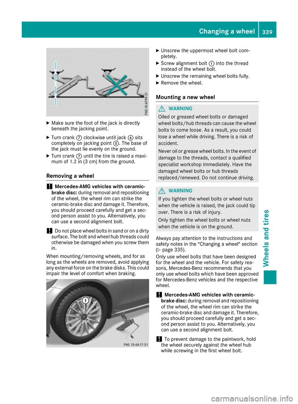
XMake sure the foot of the jack is directly
beneath the jackingpoint.
XTurn crankCclockwise until jack Bsits
completely on jackingp ointA.T he base of
the jack must lie evenly on the ground.
XTurn crank Cuntil the tire is raised amaxi-
mum of 1.2 in (3 cm) from the ground.
Removing awheel
!Mercedes-AMG vehiclesw ith ceramic-
brake disc: during removal and repositioning
of the wheel, the wheel rim can strike the
ceramic-brake disc and damage it. Therefore,
you should proceed carefully and get asec-
ond person assist to you. Alternatively, you
can use asecond alignment bolt.
!Do not place wheel bolts in sand or on adirty
surface. The bolt and wheel hub threads could
otherwise be damaged when you screw them
in.
When mounting/removing wheels, and for as
long as the wheels are removed, avoid applying
any external force on the brake disks. This could
impair the level of comfort when braking.
XUnscrew the uppermost wheel bolt com-
pletely.
XScrew alignment bolt :into the thread
instead of the wheel bolt.
XUnscrew the remaining wheel bolts fully.
XRemove the wheel.
Mounting anew wheel
GWARNING
Oiled or greased wheel bolts or damaged
wheel bolts/hub threads can cause the wheel bolts to come loose. As aresult, you could
lose awheel while driving. There is arisk of
accident.
Never oil or grease wheel bolts. In the event of
damage to the threads, contact aqualified
specialist workshop immediately. Have the
damaged wheel bolts or hub threads
replaced/renewed. Do not continue driving.
GWARNING
If you tighten the wheel bolts or wheel nuts
when the vehicle is raised, the jack could tip
over. There is arisk of injury.
Only tighten the wheel bolts or wheel nuts
when the vehicle is on the ground.
Always pay attention to the instructions and
safety notes in the "Changing awheel" section
(
Ypage 335).
Only use wheel bolts that have been designed
for the wheel and the vehicle. For safety rea-
sons, Mercedes-Benzr ecommends that you
only use wheel bolts which have been approved for Mercedes-Benzv ehicles and the respective
wheel.
!Mercedes-AMG vehiclesw ith ceramic-
brake disc: during removal and repositioning
of the wheel, the wheel rim can strike the
ceramic-brake disc and damage it. Therefore,
you should proceed carefully and get asec-
ond person assist to you. Alternatively, you
can use asecond alignment bolt.
!To prevent damage to the paintwork, hold
the wheel securely against the wheel hub
while screwing in the first wheel bolt.
Changing awheel339
Wheels and tires
Z
Page 342 of 354

XClean thewheel and wheel hub contact sur-
faces.
XSlid ethe wheel to bemounte dontot he align-
men tbolt and push iton.
XTighte nthe wheel boltsuntilthey are finger-
tight.
XUnscrew th ealignmen tbolt.
XTighte nthe last wheel boltuntil it is finger-
tight.
Lowering th evehicle
GWAR NING
The wheelsc ouldwork looseift hewheel nuts
and boltsare no ttightened to th especifie d
tightening torque. Thereisar iskofa cciden t.
Hav ethe tightening torque immediately
checked at aqualified specialist workshop
after awheel ischanged.
XTurn th ecrank of th ejackc ounter-clock wise
unt ilth ev ehicle is once again standing firmly
on th eground.
XPlacet hejacktoo neside.
XTighte nthe wheel boltsevenly inac rosswise
pattern inthes equenc eindicated (: toA). The specifie
dtightening torque is 96lb-ft
(1 30 Nm) .
XTurn th ejackb ack to its initial position.
XStow th ejac ka nd th erestoft hevehicle tools
in thet runk again.
XMercedes-AM Gvehicles and vehicles
with AMG equipment: insert thecover into
th eo uter sill.
XCheckt hetirep ressureoft henewly mounted
wheel and adjust it if necessary.
Observ ethe recommended tir epressure
(
Ypage 319).
When you are driving withthe collapsible spare
wheel mounte d,thet irep ressurel oss warning
system or th etirep ressurem onitorcanno tfunc-
tio nr eliably. Only restartthe tirep ressurel oss
warning system or tir epressurem onitorwhen
th ed efective wheel has been replace dwitha
ne ww heel.
Vehicles with atirep ressure control sys-
tem: all installed wheelsm ust be equippedwith
functioning sensors.
Wheel-tire combination
You can ask for informatio nregardin gpermitted
wheel-tire co mbinations at an authorized
Mercedes-Ben zCenter.
!For safety reasons, Mercedes-Ben zrecom-
men dsthat you only use tires and wheels
whic hhave been approvedbyM ercedes-Benz
specifically for your vehicle.
Theset ires have been specially adapted for
use witht hecontrol systems ,suchasA BSor
ESP
®,a nd are marke dasfollows:
RMO= Mercedes-Ben zOriginal
RMOE = Mercedes-Ben zOriginal Extended
(tires featurin grun-flat characteristics)
RMO1 = Mercedes-Ben zOriginal (only cer-
tain AM Gtires)
Mercedes-Ben zOriginal Extende dtires may
only be used on wheelst hath ave been spe-
cificall yapprove dbyMercedes-Benz.
Only use tires, wheelsora ccessoriestested
and approve dbyMercedes-Benz. Certain
characteristics, e.g .handling, vehicle noise
emissionsorf uel consumption,m ay other-
wise be adverselyaffected. In addition,w hen
driv ingwithal oad, tir edimension variations
could caus ethe tires to come int ocontac t
340Wheel-tirec ombination
Wheels and tires
Page 343 of 354

with thebodyworka nd axle components. This
could result in damage to th etires or th evehi-
cle.
Mercedes-Ben zacceptsnol iabilityfor dam-
age resulting fromt heuse of tires, wheels or
accessories other than those tested and
approved.
Information on tires, wheels and approved
combinations can be obtained froma ny quali-
fied specialist workshop.
!Retreaded tires are neither tested nor rec-
ommended by Mercedes-Benz, since previ-
ous damage cannot always be detected on
retreaded tires. As aresult ,Mercedes-Benz
cannot guarantee vehicle safetyifr etreaded
tires are mounted .Donot mountu sed tires if
you have no information about their previous
usage.
The recommended pressures for various oper-
atin gconditions can be found:
Ron th eTire and LoadingI nformation placard
on th eB-pillar on th edriver's side
Rin th etirep ressure table in th efuel filler flap
Observe th enotes on recommended tir epres-
sures under various operatin gconditions
(
Ypage 319).
Check tir epressures regularly, and only when
th et ires are cold .Comply with th emaintenance
recommendation softhetirem anufacturer in
th ev ehicle documentw allet.
Notes on th evehicle equipment –always equip
th ev ehicle with:
Rwith tires of th esame sizeonag iven axle (left
and right)
Rth es ame type of tires at agiven tim e(summer
tires, winter tires, MOExtended tires)
Exception: it is permissible to install adiffer-
ent type or makeint heeventofaf lat tire.
Observe t
h e"MOExtended tires (tires with
run-flat characteristics" sectio n(Ypage 301).
Vehicles equipped with MOExtended tires are
not equipped with aTIREFIT kit at th efactory. It
is therefore recommended that you additionally
equip your vehicle with aTIREFIT kit if you mount
tires that do not feature run-flat properties, e.g.
winter tires. ATIREFI Tkit may be obtained from
aq ualified specialist workshop.
Wheel-tire combination341
Wheels and tires
Z
Page 344 of 354

Information regardingtechnicald ata
i
The dat astate dh eres pecifically refers to a
vehicl ewiths tandard equipment. Consult an
authorize dMercedes-Ben zCente rfor th e
dat afor all vehicl evariants and trim levels.
Vehicle electronics
Installing two-way radio sand mobile
phones (RF transmitters)
GWARNIN G
The electromagneti cradiation from modifie d
or incorrectl yretrofitte dRF-transmitters can
interfere wit hthe vehicl eelectronics .This can
compromise th eoperational safet yofthe
vehicle. Ther eisariskofana ccident.
You should hav eall wor ktoe lectrical and
electronic equipmen tcarried out at aqualified
specialist workshop.
GWARNIN G
The electromagneti cradiation from incor-
rectl yoperate dRFtransmitters can interfere
wit hthe vehicl eelectronics ,for example:
Rif th eRFt ransmitte risnotconnecte dwith
an exterio rantenna
Rthee xter iora ntenna has been installed
incorrectl yorisnotalow-reflection typ e
This can compromise th eoperational safet y
of th evehicle. Ther eisariskofana ccident.
Hav ethe low-reflection exterio rantenna
mounte dataqualified specialist workshop.
When operating RF transmitters in th evehi-
cle ,always connec tthe mw itht he low-reflec -
tion exterio rantenna.
!The operating permit may be invalidated if
th ei nstruction sfor installation and use of RF
transmitters are no tobserved. In particular, th
efollowin gconditi onsm ust be
complied with:
Ronly approve dwavebands may be used.
Rcomplianc ewitht he maximum permissible
output in these wavebands is required.
Ronly approve dantenna position smay be
used.
Excessiv elevels of electromagneti cradiation
may caus edamag etoyour healt hand th ehealt h
of others. Using an exterio rantenna takes int o
accoun tcurren tscientific discussion srelating
to th epossible healt hhazards that may result
from elec tro
magneti
cfields.
Approved antenna position s
:
Fron troo fa rea
;Rear roo farea
=Rear fender
?Tailgate
iOn vehicles wit hpanoram aroofw ithp ower
tilt/slidin gpanel, installin ganantenna to th e
fron torr ear roo farea is no tpermitted.
On th erear fenders, it is recommended to
position th eantenna on th eside of th evehicl e
closes ttothecenter of th eroad .
Use th eTechnical Specification ISO/TS 2160 9
when retrofitting RF transmitters (Road Vehicles
-E MC guidelines for installation of aftermarket
radi ofrequency transmitting equipment) .
Observ ethe legal requirements for accessory
parts.
If your vehicl ehas installation sfor two-way radi o
equipment, use th epower suppl yorantenna
connection sintended for use wit hthe basic wir-
ing .Bes uretoo bservethe manufacturer' sSup-
plemen twhen installing.
Deviation swithr espec ttofrequency bands,
maximum transmission output sorantenna
position smust be approve dbyMercedes-Benz.
342Vehicle electronics
Technical data