2017 FORD EXPEDITION EL lock
[x] Cancel search: lockPage 260 of 500

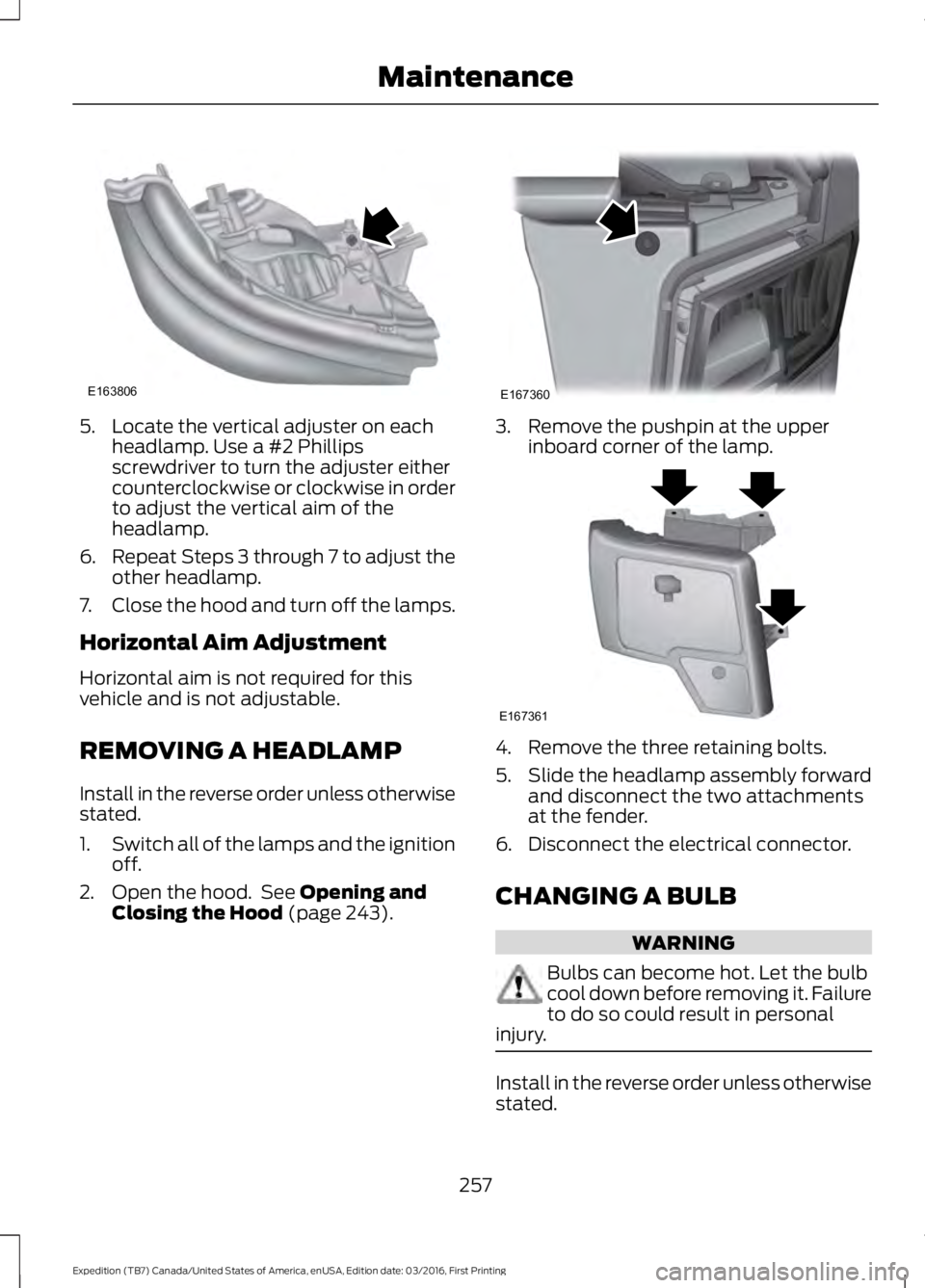
5. Locate the vertical adjuster on eachheadlamp. Use a #2 Phillipsscrewdriver to turn the adjuster eithercounterclockwise or clockwise in orderto adjust the vertical aim of theheadlamp.
6.Repeat Steps 3 through 7 to adjust theother headlamp.
7.Close the hood and turn off the lamps.
Horizontal Aim Adjustment
Horizontal aim is not required for thisvehicle and is not adjustable.
REMOVING A HEADLAMP
Install in the reverse order unless otherwisestated.
1.Switch all of the lamps and the ignitionoff.
2. Open the hood. See Opening andClosing the Hood (page 243).
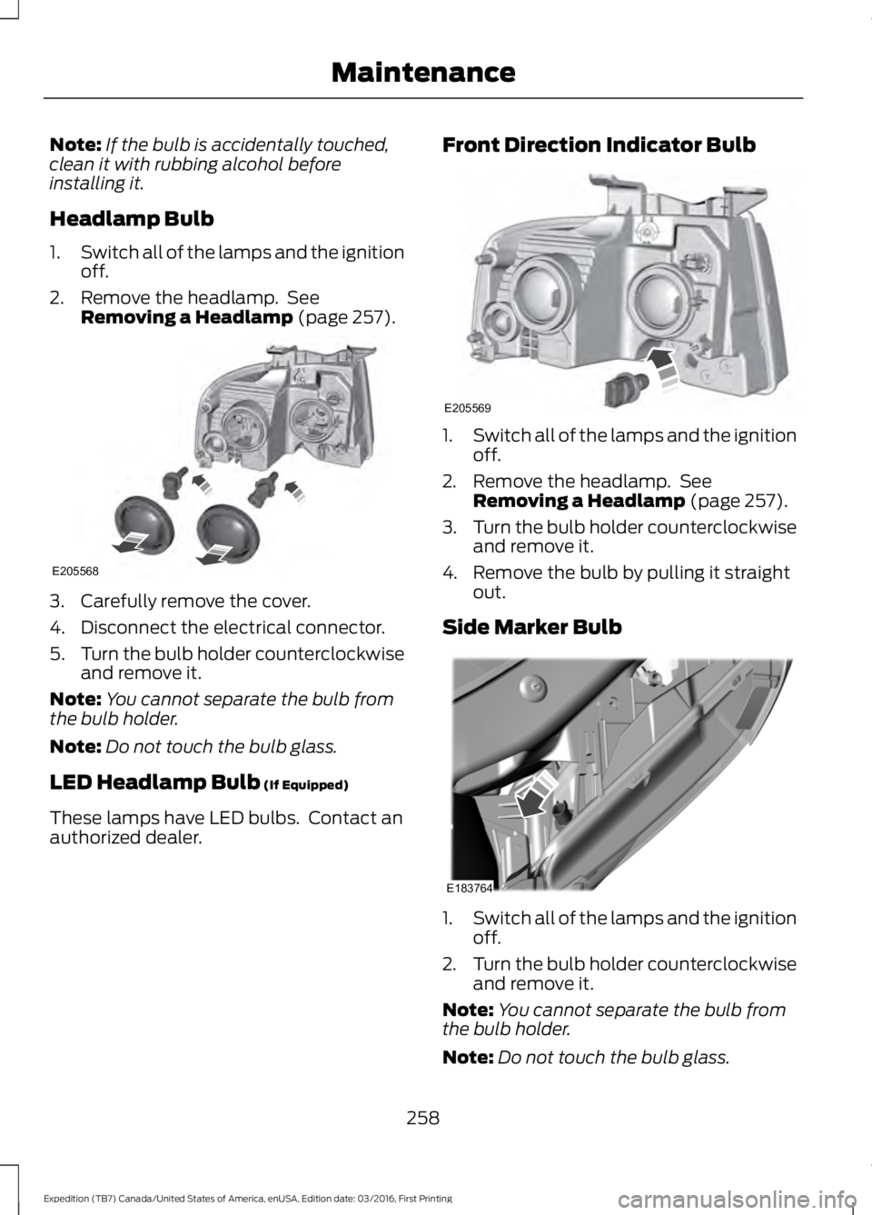
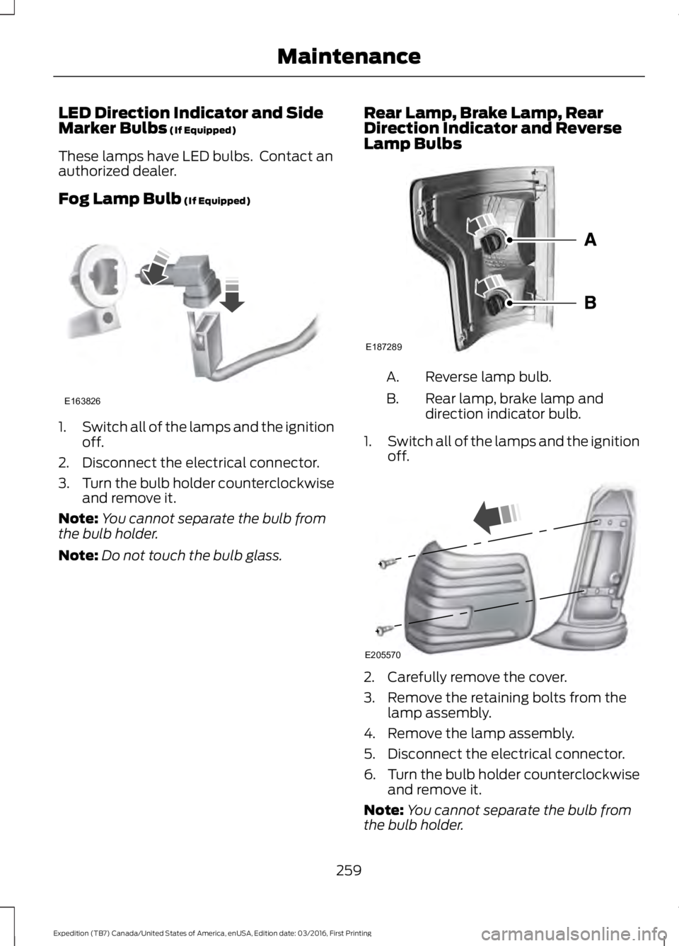
3. Remove the pushpin at the upperinboard corner of the lamp.
4. Remove the three retaining bolts.
5.Slide the headlamp assembly forwardand disconnect the two attachmentsat the fender.
6. Disconnect the electrical connector.
CHANGING A BULB
WARNING
Bulbs can become hot. Let the bulbcool down before removing it. Failureto do so could result in personalinjury.
Install in the reverse order unless otherwisestated.
257
Expedition (TB7) Canada/United States of America, enUSA, Edition date: 03/2016, First Printing
MaintenanceE163806 E167360 E167361
Page 261 of 500

Note:If the bulb is accidentally touched,clean it with rubbing alcohol beforeinstalling it.
Headlamp Bulb
1.Switch all of the lamps and the ignitionoff.
2. Remove the headlamp. SeeRemoving a Headlamp (page 257).
3. Carefully remove the cover.
4. Disconnect the electrical connector.
5.Turn the bulb holder counterclockwiseand remove it.
Note:You cannot separate the bulb fromthe bulb holder.
Note:Do not touch the bulb glass.
LED Headlamp Bulb (If Equipped)
These lamps have LED bulbs. Contact anauthorized dealer.
Front Direction Indicator Bulb
1.Switch all of the lamps and the ignitionoff.
2. Remove the headlamp. SeeRemoving a Headlamp (page 257).
3.Turn the bulb holder counterclockwiseand remove it.
4. Remove the bulb by pulling it straightout.
Side Marker Bulb
1.Switch all of the lamps and the ignitionoff.
2.Turn the bulb holder counterclockwiseand remove it.
Note:You cannot separate the bulb fromthe bulb holder.
Note:Do not touch the bulb glass.
258
Expedition (TB7) Canada/United States of America, enUSA, Edition date: 03/2016, First Printing
MaintenanceE205568 E205569 E183764
Page 262 of 500

LED Direction Indicator and SideMarker Bulbs (If Equipped)
These lamps have LED bulbs. Contact anauthorized dealer.
Fog Lamp Bulb (If Equipped)
1.Switch all of the lamps and the ignitionoff.
2. Disconnect the electrical connector.
3.Turn the bulb holder counterclockwiseand remove it.
Note:You cannot separate the bulb fromthe bulb holder.
Note:Do not touch the bulb glass.
Rear Lamp, Brake Lamp, RearDirection Indicator and ReverseLamp Bulbs
Reverse lamp bulb.A.
Rear lamp, brake lamp anddirection indicator bulb.B.
1.Switch all of the lamps and the ignitionoff.
2. Carefully remove the cover.
3. Remove the retaining bolts from thelamp assembly.
4. Remove the lamp assembly.
5. Disconnect the electrical connector.
6.Turn the bulb holder counterclockwiseand remove it.
Note:You cannot separate the bulb fromthe bulb holder.
259
Expedition (TB7) Canada/United States of America, enUSA, Edition date: 03/2016, First Printing
MaintenanceE163826 E187289 E205570
Page 263 of 500

LED Rear Lamp, Brake Lamp, RearDirection Indicator and ReverseLamp Bulbs (If Equipped)
These lamps have LED bulbs. Contact anauthorized dealer.
Central High-mounted Brake LampBulb
1.Switch all of the lamps and the ignitionoff.
2. Remove the retaining bolts from thelamp assembly.
3. Remove the lamp and unclip the bulbholder.
4. Remove the bulb by pulling it straightout.
LED Central High-mounted BrakeLamp Bulb (If Equipped)
These lamps have LED bulbs. Contact anauthorized dealer.
License Plate Lamp Bulb
1. Use a suitable tool, for example ascrewdriver, to carefully remove thelamp.
2.Turn the bulb holder counterclockwiseand remove it.
3. Remove the bulb by pulling it straightout.
Side Direction Indicator Bulb
These lamps have LED bulbs. Contact anauthorized dealer.
BULB SPECIFICATION CHART
Replacement bulbs are specified in thechart below. Headlamp bulbs must bemarked with an authorized D.O.T. markingfor North America to make sure they havethe proper lamp performance, lightbrightness, light pattern and safe visibility.The correct bulbs will not damage thelamp assembly or void the lamp assemblywarranty and will provide quality bulbillumination time.
260
Expedition (TB7) Canada/United States of America, enUSA, Edition date: 03/2016, First Printing
MaintenanceE205572 E205573 E205571
Page 265 of 500

CHANGING THE ENGINE AIR
FILTER
WARNING
To reduce the risk of vehicle damageand personal burn injuries, do notstart your engine with the air cleanerremoved and do not remove it while theengine is running.
Note: Failure to use the correct air filterelement may result in severe enginedamage. Resulting component damagemay not be covered by the vehicle Warranty.
When changing the air filter element, useonly the air filter element listed. SeeMotorcraft Parts (page 304).
Change the air filter element at the correctinterval. See Scheduled Maintenance(page 443).
1. Locate the mass air flow sensorelectrical connector on the air outlettube. Disconnect the mass air flowsensor electrical connector.
2. Reposition the locking clip on theconnector (connector shown frombelow for clarity), squeeze theconnector and pull it off of the airoutlet tube.
3.Clean the area from around the air tubeto the air cover connection to preventdebris from entering the system. Next,loosen the bolt on the air tube clampso the clamp is no longer snug to theair tube. It is not necessary tocompletely remove the clamp.
4.Pull the air tube off from the air cleanerhousing.
262
Expedition (TB7) Canada/United States of America, enUSA, Edition date: 03/2016, First Printing
MaintenanceE163755 E163756 E163757
Page 266 of 500

5. Release the three clamps that securethe cover to the air filter housing. Pushthe air filter cover toward the center ofthe vehicle and up slightly to release it.
6.Remove the air filter element from theair filter housing.
7. Install the new air filter element.
8.Replace the air filter housing cover andsecure all the clamps. Be careful notto crimp the filter element edgesbetween the air filter housing and coverand ensure that you properly align thetabs on the edge into the slots.
9. Slip the air tube onto the air filterhousing and tighten the air-tube clampbolt snugly. Do not over tightenair-tube clamp bolt.
10. Reconnect the mass air flow sensorelectrical connector to the outlettube. Make sure the locking tab onthe connector is in the locked position(connector shown from below forclarity).
263
Expedition (TB7) Canada/United States of America, enUSA, Edition date: 03/2016, First Printing
MaintenanceE163758 E163759 E163760
Page 269 of 500

Note:Holding the pressure washer nozzleat an angle to the vehicle's surface maydamage graphics and cause the edges topeel away from the vehicle's surface.
Underbody
Flush the complete underside of yourvehicle frequently. Keep body and doordrain holes free of debris or foreignmaterial.
Under Hood
For removing black rubber marks fromunder the hood we recommend MotorcraftWheel and Tire Cleaner or Motorcraft Bugand Tar Remover.
WAXING
Regular waxing is necessary to protect yourcar's paint from the elements. Werecommend that you wash and wax thepainted surface once or twice a year.
When washing and waxing, park yourvehicle in a shaded area out of directsunlight. Always wash your vehicle beforeapplying wax.
•Use a quality wax that does not containabrasives.
•Follow the manufacturer’s instructionsto apply and remove the wax.
•Apply a small amount of wax in aback-and-forth motion, not in circles.
•Do not allow wax to come in contactwith any non-body (low-gloss black)colored trim. The wax will discolor orstain the parts over time.
•Roof racks.
•Bumpers.
•Grained door handles.
•Side moldings.
•Mirror housings.
•Windshield cowl area.
•Do not apply wax to glass areas.
•After waxing, your car's paint shouldfeel smooth, and be free of streaks andsmudges.
CLEANING THE ENGINE
Engines are more efficient when they areclean because grease and dirt buildup keepthe engine warmer than normal.
When washing:
•Take care when using a power washerto clean the engine. The high-pressurefluid could penetrate the sealed partsand cause damage.
•Do not spray a hot engine with coldwater to avoid cracking the engineblock or other engine components.
•Spray Motorcraft Engine Shampoo andDegreaser on all parts that requirecleaning and pressure rinse clean. InCanada, use Motorcraft EngineShampoo.
•Never wash or rinse the engine while itis hot or running; water in the runningengine may cause internal damage.
266
Expedition (TB7) Canada/United States of America, enUSA, Edition date: 03/2016, First Printing
Vehicle Care
Page 299 of 500

•To reduce the chances of interferencefrom another vehicle, perform thesystem reset procedure at least threefeet (one meter) away from anotherFord Motor Company vehicleundergoing the system reset procedureat the same time.
•Do not wait more than two minutesbetween resetting each tire sensor orthe system will time-out and the entireprocedure will have to be repeated onall four wheels.
•A double horn will sound indicating theneed to repeat the procedure.
Performing the System Reset Procedure
Read the entire procedure beforeattempting.
1. Drive the vehicle above 20 mph (32km/h) for at least two minutes, thenpark in a safe location where you caneasily get to all four tires and haveaccess to an air pump.
2.Place the ignition in the off position andkeep the key in the ignition.
3. Cycle the ignition to the on positionwith the engine off.
4. Turn the hazard flashers on then offthree times. You must accomplish thiswithin 10 seconds. If the reset modehas been entered successfully, the hornwill sound once, the system indicatorwill flash and a message is shown inthe information display. If this does notoccur, please try again starting at Step2. If after repeated attempts to enterthe reset mode, the horn does notsound, the system indicator does notflash and no message is shown in theinformation display, seek service fromyour authorized dealer.
5. Train the tire pressure monitoringsystem sensors in the tires using thefollowing system reset sequencestarting with the left front tire in thefollowing clockwise order: Left front(driver's side front tire), Right front(passenger's side front tire), Right rear(passenger's side rear tire), Left rear(driver's side rear tire).
6. Remove the valve cap from the valvestem on the left front tire. Decrease theair pressure until the horn sounds.
Note:The single horn chirp confirms thatthe sensor identification code has beenlearned by the module for this position. If adouble horn is heard, the reset procedurewas unsuccessful, and you must repeat it.
7. Remove the valve cap from the valvestem on the right front tire. Decreasethe air pressure until the horn sounds.
8. Remove the valve cap from the valvestem on the right rear tire. Decrease theair pressure until the horn sounds.
9. Remove the valve cap from the valvestem on the left rear tire. Decrease theair pressure until the horn sounds.Training is complete after the hornsounds for the last tire trained (driver'sside rear tire), the system indicatorstops flashing, and a message is shownin the information display.
10.Turn the ignition off. If two short hornbeeps are heard, the reset procedurewas unsuccessful and you mustrepeat it. If after repeating theprocedure and two short beeps areheard when the ignition is turned tooff, seek assistance from yourauthorized dealer.
296
Expedition (TB7) Canada/United States of America, enUSA, Edition date: 03/2016, First Printing
Wheels and Tires