2017 FORD EXPEDITION EL lock
[x] Cancel search: lockPage 214 of 500
The controller shows gain setting, outputbar graph, and trailer connectivity statusin the information display. They appear inthe information display as follows:
•Trailer Brake Controller Gain (withouttrailer connected): Shows the currentgain setting during a given ignition cycleand when adjusting the gain. This alsodisplays if you use the manual controllever or make gain adjustments withno trailer connected.
•Trailer Brake Controller Gain Output:Displays when you push your vehicle'sbrake pedal, or upon use of the manualcontrol. Bar indicators illuminate in theinformation display to indicate theamount of power going to the trailerbrakes relative to the brake pedal ormanual control input. One bar indicatesthe least amount of output; six barsindicate maximum output.
•Trailer Connected: Displays when thesystem senses a correct trailer wiringconnection (a trailer with electric trailerbrakes) during a given ignition cycle.
•Trailer Disconnected: Displays,accompanied by a single audible time,when the system senses a trailerconnection and then a disconnection,either intentional or unintentional,during a given ignition cycle. It alsodisplays if a truck or trailer-wiring faultoccurs causing the trailer to appeardisconnected. This message can alsodisplay if you use the manual controllever without a trailer connected. Afterdisconnecting the trailer connector,press the brake pedal forapproximately five seconds to allowthe system to detect and update thetrailer status.
B: Manual control lever: Slide the controllever to the left to turn on the trailer'selectric brakes independent of the towvehicle's. See the following Procedure foradjusting gain section for instructions onproper use of this feature. If you use themanual control while the brake is alsoapplied, the greater of the two inputsdetermines the power sent to the trailerbrakes.
•Stop lamps: Using the manual controllever illuminates both the trailer brakelamps and your vehicle brake lampsexcept the center high-mount stoplamp, if you make the proper electricalconnection to the trailer. Pressing yourvehicle brake pedal also illuminatesboth trailer and vehicle brake lamps.
Procedure for Adjusting Gain
Note:Only perform this procedure in atraffic-free environment at speeds ofapproximately 20-25 mph (30-40 km/h).
The gain setting sets the trailer brakecontroller for the specific towing condition.You should change the setting as towingconditions change. Changes to towingconditions include trailer load, vehicle load,road conditions and weather.
The gain should be set to provide themaximum trailer braking assistance whilemaking sure the trailer wheels do not lockwhen using the brakes. Locked trailerwheels may lead to trailer instability.
1.Make sure the trailer brakes are in goodworking condition, functioning normallyand properly adjusted. See your trailerdealer if necessary.
2. Hook up the trailer and make theelectrical connections according to thetrailer manufacturer's instructions.
3. When you plug in a trailer with electricor electric-over-hydraulic brakes, amessage confirming connectionappears in the information display.
211
Expedition (TB7) Canada/United States of America, enUSA, Edition date: 03/2016, First Printing
Towing
Page 215 of 500
4. Use the gain adjustment (+ and -)buttons to increase or decrease thegain setting to the desired startingpoint. A gain setting of 6.0 is a goodstarting point for heavier loads.
5. In a traffic-free environment, tow thetrailer on a dry, level surface at a speedof 20-25 mph (30-40 km/h) andsqueeze the manual control levercompletely.
6. If the trailer wheels lock up, indicatedby squealing tires, reduce the gainsetting. If the trailer wheels turn freely,increase the gain setting. Repeat Steps5 and 6 until the gain setting is at apoint just below trailer wheel lock-up.If towing a heavier trailer, trailer wheellock-up may not be attainable evenwith the maximum gain setting of 10.
Explanation of Information DisplayWarning Messages
Note:An authorized dealer can diagnosethe trailer brake controller to determineexactly which trailer fault has occurred.However, your Ford warranty does not coverthis diagnosis if the fault is with the trailer.
A message indicating a trailer brakemodule fault may display in response tofaults sensed by the trailer brake controller,accompanied by a single tone. If thismessage appears, contact an authorizeddealer as soon as possible for diagnosisand repair. The controller may stillfunction, but performance may bedegraded.
A message indicating a trailer wiring faultmay display when there is a short circuiton the electric brake output wire. If thismessage displays, accompanied by asingle tone, with no trailer connected, theproblem is with your vehicle wiringbetween the trailer brake controller andthe 7-pin connector at the bumper. If themessage only displays with a trailerconnected, the problem is with the trailer
wiring. Consult your trailer dealer forassistance. This can be a short to ground(such as a chaffed wire), short to voltage(such as a pulled pin on trailer emergencybreakaway battery) or the trailer brakesmay be drawing too much current.
Points to Remember
Note:Do not attempt removal of the trailerbrake controller without consulting theWorkshop Manual. Damage to the unit mayresult.
•Adjust gain setting before using thetrailer brake controller for the first time.
•Adjust gain setting, using the procedureabove, whenever road, weather andtrailer or vehicle loading conditionschange from when the gain was initiallyset.
•Only use the manual control lever forproper adjustment of the gain duringtrailer setup. Misuse, such asapplication during trailer sway, couldcause instability of trailer or towvehicle.
•Avoid towing in adverse weatherconditions. The trailer brake controllerdoes not provide anti-lock control ofthe trailer wheels. Trailer wheels canlock up on slippery surfaces, resultingin reduced stability of trailer and towvehicle.
•The trailer brake controller is equippedwith a feature that reduces output atvehicle speeds below 11 mph (18 km/h)so trailer and vehicle braking is not jerkyor harsh. This feature is only availablewhen applying the brakes using yourvehicle's brake pedal, not thecontroller.
•The controller interacts with the brakecontrol system and powertrain controlsystem of your vehicle to provide thebest performance on different roadconditions.
212
Expedition (TB7) Canada/United States of America, enUSA, Edition date: 03/2016, First Printing
Towing
Page 218 of 500
Before using recovery hooks:
•Make sure all attaching points aresecure and capable of withstandingthe applied load.
•Never use chains, cables or tow strapswith metal hook ends.
•Only use recovery straps that have aminimum breaking strength two tothree times the gross vehicle weight ofthe stuck vehicle.
•Make sure the recovery strap is in goodcondition and free of visible cuts, tearsor damage.
•Use a damper device such as a tarp,heavy blanket or piece of carpetdraped over the recovery strap to helpabsorb the energy in the event thestrap breaks.
•Make sure the stuck vehicle is notloaded heavier than its gross vehicleweight rating specified on thecertification label.
•Always align the tow vehicle and stuckvehicle in a straight line (within 10degrees).
•Keep bystanders to the sides of thevehicle, at a distance of at least twicethe length of the recovery strap. Thishelps avoid injury from the hazard of arecovery hook or strap breaking, or avehicle lurching into their path.
TOWING THE VEHICLE ON
FOUR WHEELS
WARNING
If your vehicle has a steering wheellock make sure the ignition is in theaccessory or on position when beingtowed.
Emergency Towing
If your vehicle becomes inoperable(without access to wheel dollies,car-hauling trailer, or flatbed transportvehicle), it can be flat-towed (all wheelson the ground, regardless of the powertrainand transmission configuration) under thefollowing conditions:
•Your vehicle is facing forward fortowing in a forward direction.
•Place the transmission in position N. Ifyou cannot move the transmission intoN, you may need to override it. SeeTransmission (page 159).
•Maximum speed is 35 mph (56 km/h).
•Maximum distance is 50 mi (80 km).
Recreational Towing
Note:Put your climate control system inrecirculated air mode to prevent exhaustfumes from entering your vehicle. SeeClimate Control (page 112).
Follow these guidelines if you have a needfor recreational towing, for example towingyour vehicle behind a motorhome. Theseguidelines prevent damage to yourtransmission.
Two Wheel Drive Vehicles
You cannot tow a two wheel drive vehiclewith any wheels on the ground as vehicleor transmission damage may occur. Youmust tow your vehicle with all four wheelsoff the ground, for example when using acar-hauling trailer.
215
Expedition (TB7) Canada/United States of America, enUSA, Edition date: 03/2016, First Printing
Towing
Page 219 of 500
Four Wheel Drive Vehicles
You can only tow a four wheel drive vehiclewith all wheels on the ground by placingthe transfer case in its neutral position andengaging the four-wheel-down towingfeature. Perform the steps outlined in thefollowing section after positioning yourvehicle behind the tow vehicle and properlysecuring them together.
Four-wheel-down Towing
Note:Make sure you properly secure yourvehicle to the tow vehicle.
Entering Four-wheel-down Towing
1. Put the ignition in the on position, butdo not start the engine. If your vehiclehas an ignition key, turn the key to on.If your vehicle has intelligent access,press the engine START/STOP buttontwice without pressing the brake pedal.
2. Press and hold the brake pedal.
3. Rotate the four-wheel drive switch to2H.
4. Shift the transmission to position N.
5. Rotate the four-wheel drive switchfrom 2H to 4L and back to 2H fivetimes within seven seconds.
Note:If completed successfully, theinformation display shows NEUTRAL TOWLEAVE IN N or NEUTRAL TOW ENABLEDLEAVE TRANSMISSION IN NEUTRAL.This indicates that your vehicle is safe totow with all wheels on the ground.
Note:If you do not see the message in thedisplay, you must perform the procedureagain from the beginning.
Note:You may hear an audible noise as thetransfer case shifts into its neutral position.This is normal.
6. Leave the transmission in position Nand turn the ignition as far as it will gotoward the off position (it will not turnfully off when the transmission is inposition N). If your vehicle has anignition key, you must leave the key inthe ignition while towing. To lock andunlock your vehicle, use the keylessentry keypad or extra set of keys. If yourvehicle has intelligent access, press theengine START/STOP button oncewithout pressing the brake pedal. Youdo not need to leave your keys in thevehicle. You can lock and unlock yourvehicle as you normally do.
7. Release the brake pedal.
WARNINGS
Do not disconnect the battery duringrecreational towing. Doing so willprevent the transfer case fromshifting properly and may cause the vehicleto roll even if the transmission is in P(Park).
Shifting the transfer case to itsneutral position for recreationaltowing may cause the vehicle to beable to roll even if the transmission is in P(Park). The driver or others could beinjured. Make sure the foot brake isdepressed and the vehicle is in a secureand safe position while the transfer caseis being shifted to its neutral position.
Failing to put the transfer case in itsneutral position will damage vehiclecomponents.
Note:You can check four-wheel-downtowing status at any time by opening thedriver's door or turning the ignition to theaccessory or on position and verifying theNEUTRAL TOW ENABLED messagedisplays in the cluster.
216
Expedition (TB7) Canada/United States of America, enUSA, Edition date: 03/2016, First Printing
Towing
Page 220 of 500
Exiting Four-wheel-down Towing
To exit four-wheel-down towing and returnthe transfer case to its 2H position:
1.With your vehicle still properly securedto the tow vehicle, put the ignition inthe on position, but do not start theengine. If your vehicle has an ignitionkey, turn the key to on. If your vehiclehas intelligent access, press the engineSTART/STOP button twice withoutpressing the brake pedal.
2. Press and hold the brake pedal.
3.Shift the transmission out of N and intoany gear.
4. Release the brake pedal.
Note:If completed successfully, theinstrument cluster displays 4X2, andNEUTRAL TOW DISABLED.
Note:If the indicator light and message donot display, you must perform the procedureagain from the beginning.
Note:You may hear an audible noise as thetransfer case shifts out of its neutralposition. This is normal.
Note:If SHIFT DELAY PULL FORWARDdisplays in the instrument cluster, transfercase gear tooth blockage is present. See theinstructions after this section.
5. Apply the parking brake, and thendisconnect the vehicle from the towvehicle.
6. Release the parking brake, start theengine, and shift the transmission toposition D to make sure the transfercase is out of position N.
7. If the transfer case does notsuccessfully shift out of position N, setthe parking brake until you can haveyour vehicle serviced.
Resolving the SHIFT DELAY PULLFORWARD Message
If the instrument cluster displays SHIFTDELAY PULL FORWARD perform thefollowing:
1. Press and hold the brake pedal.
2. Put the transmission into position N,and then start the engine.
3. With the engine running, shift thetransmission to position D and let thevehicle roll forward, up to 3 feet (1meter). You may hear an audible noiseas the transfer case shifts out of itsneutral position. This is normal.
4. Make sure the instrument clusterdisplays NEUTRAL TOW DISABLED.
217
Expedition (TB7) Canada/United States of America, enUSA, Edition date: 03/2016, First Printing
Towing
Page 223 of 500
WARNINGS
Never place floor mats or any othercovering on top of already installedfloor mats. Floor mats should alwaysrest on top of vehicle carpeting surface andnot another floor mat or other covering.Additional floor mats or any other coveringwill reduce the pedal clearance andpotentially interfere with pedal operation.
Check attachment of floor mats ona regular basis. Always properlyreinstall and secure floor mats thathave been removed for cleaning orreplacement.
Always make sure that objectscannot fall into the driver foot wellwhile the vehicle is moving. Objectsthat are loose can become trapped underthe pedals causing a loss of vehicle control.
Failure to properly follow floor matinstallation or attachmentinstructions can potentially causeinterference with pedal operation causinga loss of vehicle control.
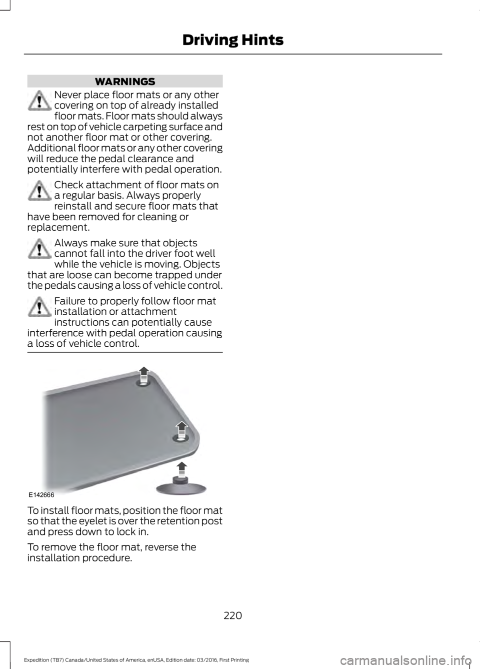
To install floor mats, position the floor matso that the eyelet is over the retention postand press down to lock in.
To remove the floor mat, reverse theinstallation procedure.
220
Expedition (TB7) Canada/United States of America, enUSA, Edition date: 03/2016, First Printing
Driving HintsE142666
Page 224 of 500
ROADSIDE ASSISTANCE
Vehicles Sold in the United States:Getting Roadside Assistance
To fully assist you should you have avehicle concern, Ford Motor Companyoffers a complimentary roadsideassistance program. This program isseparate from the New Vehicle LimitedWarranty. The service is available:
•24 hours a day, seven days a week.
•For the coverage period listed on theRoadside Assistance Card included inyour Owner's Manual portfolio.
Roadside Assistance covers:
•A flat tire change with a good spare, ifprovided with the vehicle (exceptvehicles supplied with a tire inflationkit).
•Battery jump start.
•Lock-out assistance (key replacementcost is the customer's responsibility).
•Fuel delivery — independent servicecontractors, if not prohibited by state,local or municipal law, shall deliver upto 2 gal (7.6 L) of gasoline or 5 gal(18.9 L) of diesel fuel to a disabledvehicle. Roadside Assistance limits fueldelivery service to two no-chargeoccurrences within a 12-month period.
•Winch out — available within 100 ft(30.5 m) of a paved or countymaintained road, no recoveries.
•Towing — independent servicecontractors, if not prohibited by state,local or municipal law, shall tow Fordeligible vehicles to an authorized dealerwithin 35 mi (56 km) of thedisablement location or to the nearest
authorized dealer. If a memberrequests a tow to an authorized dealerthat is more than 35 mi (56 km) fromthe disablement location, the membershall be responsible for any mileagecosts in excess of 35 mi (56 km).
Roadside Assistance includes up to $200for a towed trailer if the disabled eligiblevehicle requires service at the nearestauthorized dealer. If the towing vehicle isoperational but the trailer is not, then thetrailer does not qualify for any roadsideservices.
Vehicles Sold in the United States:Using Roadside Assistance
Complete the roadside assistanceidentification card and place it in yourwallet for quick reference. This card is inthe owner's information portfolio in theglove compartment.
United States Ford vehicle customers whorequire Roadside Assistance, call1-800-241-3673.
If you need to arrange roadside assistancefor yourself, Ford Motor Companyreimburses a reasonable amount fortowing to the nearest dealership within35 mi (56 km). To obtain reimbursementinformation, United States Ford vehiclecustomers call 1-800-241-3673.Customers need to submit their originalreceipts.
Vehicles Sold in Canada: GettingRoadside Assistance
To fully assist you should you have avehicle concern, Ford Motor Company ofCanada, Limited offers a complimentaryroadside assistance program. This programis eligible within Canada or the continentalUnited States.
221
Expedition (TB7) Canada/United States of America, enUSA, Edition date: 03/2016, First Printing
Roadside Emergencies
Page 238 of 500
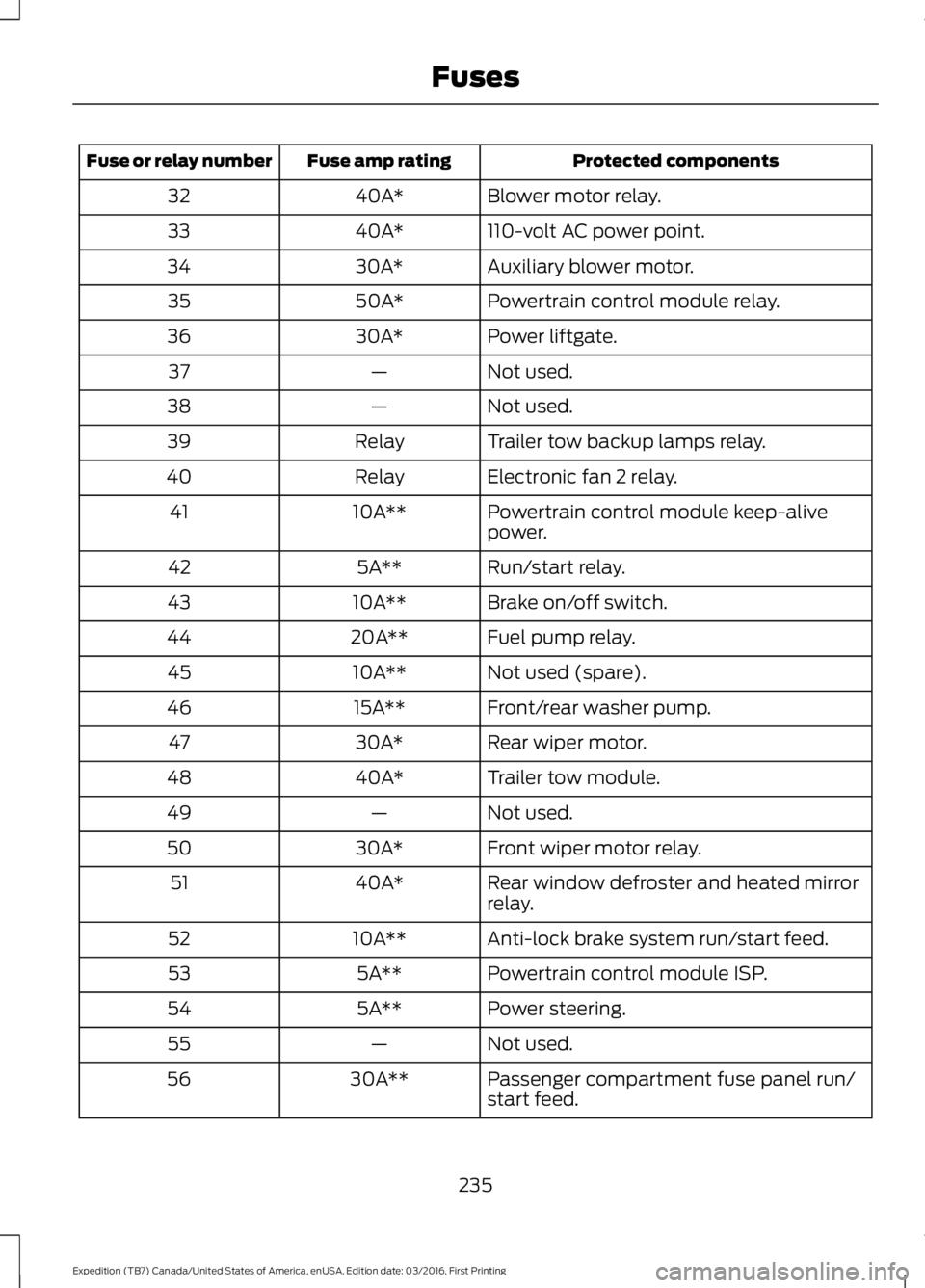
Protected componentsFuse amp ratingFuse or relay number
Blower motor relay.40A*32
110-volt AC power point.40A*33
Auxiliary blower motor.30A*34
Powertrain control module relay.50A*35
Power liftgate.30A*36
Not used.—37
Not used.—38
Trailer tow backup lamps relay.Relay39
Electronic fan 2 relay.Relay40
Powertrain control module keep-alivepower.10A**41
Run/start relay.5A**42
Brake on/off switch.10A**43
Fuel pump relay.20A**44
Not used (spare).10A**45
Front/rear washer pump.15A**46
Rear wiper motor.30A*47
Trailer tow module.40A*48
Not used.—49
Front wiper motor relay.30A*50
Rear window defroster and heated mirrorrelay.40A*51
Anti-lock brake system run/start feed.10A**52
Powertrain control module ISP.5A**53
Power steering.5A**54
Not used.—55
Passenger compartment fuse panel run/start feed.30A**56
235
Expedition (TB7) Canada/United States of America, enUSA, Edition date: 03/2016, First Printing
Fuses