Page 185 of 296

a,
a,
..... N
" ('I ..... 0 0
0:
co
LATCH lower anchorage so that the connectors
lock into place
¢ fig. 180 .
.. Pull on the connector attachments to make
sure they are p roperly attached to the LATCH
lower anchorage .
.. Pull straps tight following the child restraint
manufacturer's instructions .
Relea sing
.. Loosen the tension on the straps following the
c hild restra int manufac turer 's ins tructions .
.. Depress the spring catches to release the an
chorage hooks from the lower anchorages .
Remember: Use tether straps to he lp keep the
child rest raint firmly in place .
A WARNING
Improper use of the LATCH system can in
crease the risk of serious pe rsonal injury and
death in an acc ident.
- These anchors were developed only for child safety seats using the "LA TCH" system .
- Never attach other child safety seats, belts
or othe r objects to these anchors .
- Always make sure that you hear a click when
latch ing the seat in place. If you do not hear
a click the seat is not secure and could fly
forward and h it the interior of t he vehicle,
o r be ejected from the vehicle.
A WARNING
Improper installatio n of child rest rai nts will
increase the r is k of injury in an a cc ident.
- Always follow the child restra int system
man ufacturer's inst ru ct ions for proper in
sta llation of the child res tra int system and
pro per use of tether straps as well as the
lower anchorages or safety be lts in your
ve
hicle.
- Always read and heed the important infor
mation and WARNINGS about child safety
and the insta llation of chi ld restraint sys
tems
¢ page 168, Child safety. Ch
ild
sa fety
Tether anchors and tether straps
F ig. 181 Tet her anch ors : attachmen t hook loca tion s be
hin d the rear seatbacks
T he tether anchors for the rea r seating pos itions
are located on the backside of the rear seatbacks
¢ fig . 181 .
A tether is a straight o r V-shaped strap that a t
t a ches the top p art of a ch ild rest raint to spe cial
anchorage points in the ve hicle .
T he purpose of the tether is to reduce the for
ward movement of t he ch ild restrain t in a crash,
in order to help reduce the risk of head inju ry
that co uld be caused by striking the vehicle inte
rior.
Forward facing child restra in ts manufac tured af
ter September 1, 1999, are requ ired by U.S . fed
er al reg ulations to comply with new child head
movement performance req uirements. These
new performance requ irements mak e a t ether
necessary on most new chi ld safety seats.
A WARNING
-
Improper installation of child restra ints w ill
i ncrease the risk of injury and death in a
crash .
- Always follow the instructions prov ided by
the ma nufact urer of the ch ild restraint you
i n tend to install in your Audi .
- Improper use of chi ld restraint anchors ( in
cluding tether anchors) can lead to injury in
a co llision . The anchors are designed to
withstand only those loads imposed by cor
rectly fi tted ch ild rest rain ts.
- Neve r mo unt two child restraint systems o n
one LA TC H lowe r anchor point.
~
183
Page 186 of 296

Child safety
-Never attach two child restraint systems to
one tether strap or tether anchorage.
- Never attach a tether strap to a tie-down
hook in the luggage compartment.
- Never use chil d restraint tether anchorages
to secure safety belts or other kinds of occu
pant restraints.
- Never secure or attach any luggage or other
items to the LATCH lower anchorages or to
the tether anchors.
- If a tether or other strap is used to attach a
child restraint to the front passenger seat,
make sure that it is not so tight, that it
causes the we ight-sens ing mat to measure
more weight than is actually on the seat.
- The heav ier we ight registered can make the
Advanced Airbag System work as though an
adul t were on the seat and deploy the Ad
vanced Airbag when it must be suppressed ca using se rious or even fatal inju ry to the
child.
- If you must install a rearward fac ing ch ild
safety seat on the front passenger seat be
ca use of exceptiona l circumsta nces and the
PAS SENGER AIR BAG OFF light does not
come on and stay on, immediate ly install
the rear-fac ing chi ld safety seat in a rear
seat ing pos ition and have the airbag system
inspected by your Audi dealer.
Installing the upper tether strap on the
anchorage
F ig. 18 2 Tether strap : proper routing and mount ing
184
Fig. 1 83 Tether strap: proper routing and mount ing
Installing the tether st rap
~ Release or deploy the tether strap on the ch ild
restraint accord ing to the ch ild restraint manu
facture r's instructions.
~ Guide the upper tether s trap under the rea r
head rest raint and in to the rear cargo area
~ fig. 183 (raise the head restraint if necessa
ry). For child restraints with V -tet her straps, al
ways make sure that the head restra int guide
rods do not interfere with any pa rt of the top
tether strap.
~ Slide the tether strap hook over the anchor
bracket .
~ Pull on the tether strap hook so that the spring
ca tch of the hook engages.
~ Tighten the tether stra p firm ly following the
child restra int manufacturer's instruc tions .
Attaching to the cente r seating position
~ Slide the rear seat forward ~ page 63 .
~ Pull the anchor bracket forward and con nect
the tethe r strap hook.
~ Tigh ten the te ther strap a nd move the seat
backward.
Releasing the tether strap
~ Loosen the tension following the child restra int
manufac turer's instr uctions .
~ Depress the spr ing catch on the hook and re
lease it from t he a nch o rage.
(D Note
If yo u leave the child restraint w ith the tethe r
strap firmly installed for severa l d ays, this
could leave a mark on the upholstery on the
seat cushion and backrest in the area where
the tether strap was installed. The upholstery
IJ>
Page 187 of 296

CD
CD
.... N ,-... N .... 0 0 C<'. 00
would also be permanently stretched around
the tether strap. This applies especially to
leather seats.
Using tether straps on rearward-facing
child restraints
Currently, few rear-facing child restraint systems
come with a tether . Please read and heed the
child restraint system manufacturer's instruc
tions carefully to determine how to properly in
stall the tether.
A WARNING
A child in a rearward-facing child safety seat
installed on the front passenger seat will be
seriously injured and can be killed if the front
airbag inflates -even with an Advanced Airbag
System.
- The inflating airbag will hit the child safety seat or infant carrier with great force and
will smash the child safety seat and child against the backrest, center armrest, or
door .
-A tight tether or other strap on a rearward
facing child restraint attached to the front
passenger seat can put too much pressure
on the weight-mat in the seat and register a
heavier weight in the Advanced Airbag Sys
tem. The heavier weight registered can make the system work as though an adult
were on the seat and deploy the Advanced
Airbag when it must be suppressed causing serious or even fatal injury to the child.
- If you must install a rearward facing child
safety seat on the front passenger seat be
cause of exceptional circumstances and the
PASSENGER AIR BAG OFF light does not
come on and stay on, immediately install
the rear-facing child safety seat in a rear
seating position and have the airbag system
inspected by your Audi dealer.
Child safety
Additional information
Sources of information about child
restraints and their use
There are a number of sources of additional in
formation about child restraint selection, instal
lation and use:
NHTSA advises that the best child safety seat is
the one that fits your child and fits in your vehi
cle, and that you will use correctly and consis
tently.
Try before you buy!
U.S National Highway Traffic Safety Administra
tion
Tel. : 1-888-327-4236 (TTY: 1-800-424-9153)
http://www.nhtsa.gov
http:/ /www.safercar.gov
National SAFE KIDS Campaign
Tel. : (202) 662-0600
http://www.safekids .org
Safety BeltSafe U.S.A
Tel. : (800) 745-SAFE (English)
Tel. : (800) 747-SANO (Spanish)
http://www.carseat.org
Transport Canada Information Centre
Tel. : 1-800-333-0371 or call 1-613-998-8616 if
you are in the Ottawa area
http://www.tc.gc.ca/ eng/roadsafety/men u. htm
Audi Customer Relations
Tel.: (800) 822-2834
185
Page 188 of 296

Description
The Electronic Stabilization Control (ESC) reinfor
ces driver safety . It reduces th")
Intelligent Technology
Intelligent Technology
Electronic Stabilization
Control (ESC)
Description
The Electronic Stabilization Control (ESC) reinfor
ces driver safety . It reduces the risk of slipping
and improves driving stability. ESC detects crit i
cal s ituations such as the vehicle oversteering
and understeering or the wheels sp inning. The
veh icle is stab ilized by applying the brakes or re
ducing engine torque . Once t he ESC is active, the
indicator light
Ji) blinks in t he instrument clus
ter.
The fo llow ing systems are integrated in the ESC :
Ant i-loc k brake system (ABS)
ABS preve nts the wheels from locking up when
braking. The veh icle can still be steered even dur
ing hard brak ing. Apply steady pressure to the
brake pedal. Do not pump t he pedal. A pulsing in
the brake pedal indicates that the system is help
i n g you to brake the vehicle .
Br ake assist system
The brake assist system can decrease brak ing dis
tance . It increases braking power when the driver
presses the brake pedal quick ly in emergency sit
uations . You must press and hold the b rake pedal
until the situa tion is over. In vehicles w it h adap
tive c ruise contro l* , the brake assist system is
mo re sensit ive if the di stance de te cte d to the ve
h icle ahead is too small.
Anti -slip regulation (ASR)
ASR reduces eng ine power when the drive wheels
begin to spin and adapts t he force to the road
conditions . This makes it easie r to sta rt, acceler
ate and dr ive up h ills.
Electronic differential lock (EDL )
The EDL brakes w heels that a re spinning and
transfers the drive power to the other whee ls .
This f unction is not avai lab le at higher speeds.
In extreme cases, EDL automatically switches off
to help keep the brake on the braked wheel from
186
overheating . EDL will sw itch on again automati
ca lly when conditions have returned to normal.
Steering recommendation
The ESC he lps to s tabilize the vehicle by chang ing
t h e s teer ing torque.
On vehicles with dynam ic steeri ng*, ESC helps
stab ilize the steer ing in crit ica l sit uat io ns.
Selective wheel torque control
Se lective wheel torque cont rol is used when driv
i ng on curves. The front whee l on the inside of
the curve or both wheels on the inside of the cu rve are braked se lectively as needed. This al
l ows mo re precise dr iving in c urves . The applica
ble system may not ac tiv ate when d riving in wet
o r snowy cond it ions.
_&. WARNING
- The ESC and i ts in teg ra ted systems can not
overcome the laws of physics . This is espe
cially important on slippery or wet roads. If
the systems begin act ing to stab ilize your
veh icle, you should immediately change
your speed to match the road and traffic conditions. Do not let the increased safety
provided by t hese systems tempt yo u to
take risks. Doing so will i ncrease the r isk of
a loss of vehicle con trol, collisi on and se ri
ous person al injur ies.
- Always a dapt your speed to road, traffic and
weather condi tions. The risk of los ing c on
t rol of the vehicle in creases w hen driving
too fast, es pecially through curves and on
slippe ry or wet roads, and when driving too
close to ve hicles up ahead. The ESC and its
integ rated systems cannot always prevent
col lisions - there is still a risk of accidents!
- Always accelerate w ith special care on even,
smooth su rfaces s uch as those that are wet
or covered wit h ice and snow. The drive
wheels can spin even w it h these assistance
sys tems t hat cannot a lways help to reduce
t he risk of loss of vehicle co ntro l.
Page 189 of 296

a,
a,
..... (',J r-(',J ..... 0 0
0:
co
@ Tips
-ABS and AS R on ly work correctly when a ll
fo ur whee ls are e quipped w ith identical
tires. Different tire sizes can lead to a reduc
tion in eng ine power.
Switching on/off
Intelligent Technology
- You may hear noises when the sy stems de
scribed a re worki ng .
- Whe n in st alling a factory -s up plied roo f ra ck
system o n the roof ra iling, the ESC wi ll
adapt itself to a different center of grav ity .
ESC turns on automatically when you start the engine.
Fig . 184 Versio n A: Lower cente r console,~ OFF button
The follow ing s ituations ar e except ions where i t
may be usef ul to sw itch on offroad mode to allow
the w heels to sp in:
- Rocking the vehicle to free it when it is stuck
- Driv ing i n deep snow or on loose ground
Offroad mode on
Fig. 185 Version B : Upper center console,~ OFF butto n
-Dr iv ing with snow chains
- Dr iv ing down hill while braking on loose g round
- Dr iving on rough terra in when much of t he car's
weight is lifted off the wheels (axle artic ula
t ion)
Offroad mode off
Behavior
The ESC and ASR stabilization functions The fu ll stabilization function of the ESC
are limited
¢ ,&. .
Operation Press the 1.$ OFF I button.
Indicator Ii) tu rns on.
lights
Driver mes- St abilization control (ESC ): Offroad.
sages Warning! Restricted stability
A WARNING
- Yo u should only sw itch offroad mode o n if
yo ur dr iv ing abilit ies a nd road cond it io ns
permit.
- The stabilization function is limited when
offroad mo de is switched on. The dr iving
w he els co uld s pin and the v eh icle cou ld
swe rve, es peci ally on s lick or slipp ery roa d
s ur fac es. and ASR
is ava ilable again.
P ress the
I!.! OFFI but ton again.
II turns off.
Stabilization control (ESC ): On
(D Tips
Offroad mode cannot be switched on whe n
adaptive c ruise contro l* is switched on.
187
Page 190 of 296
ofF ___ P..1 --- fl~ IIL..~
---
Fig.")
Inte llig ent Techn olo gy
Hill descent assist
The hill descent assist makes it possible to drive
down an incline at a constant speed .
~~,·~ ('l)ofF ___ P..1 --- fl~ IIL..~
---
Fig. 186 Top of the center conso le: hill descent assist but
ton
Fig. 187 Display: hill descent assist
.. Press the~ button in the center console
¢ fig . 186 or on the shift gate . The button will
illuminate .
" Press the button again to switch it off. The di-
ode in the button will go out .
H ill descent ass ist brakes all four wheels auto
matically in order to limit speed when driving ei
ther forwa rd o r reverse on hills with a grade up to
approx imately 50%.
When the hill descent assist is on, the current
driving speed, when your vehicle entered the in
cline is maintained.
It is only possible to switch
on the assist when driving slower than 37 mph
(60 km/h). The assist works between app roxi
mately 2 and 19 mph (4 and 30 km/h) . The driver
can increase or decrease the vehicle speed within
these limits by depressing the accelerator or
brake pedal In addition, vehicle steerability is in
creased due to the braking distribution when
driving in reverse .
18 8
There must be however sufficient ground adhe
sion . The hill descent assist can
no t do its job if
the incline is icy or if the incl ine ground is loose
¢ &.
The system does not work at speeds between 19
and 37 mph (30 and 60 km/h). The system is
then in the ready-mode. The diode in the button
will come on . The system automatically sw itched
off when you drive faster than 37 mph (60 km/ h) . The diode will go out in this case .
Active control at a specific speed up to approxi
mately 19 mph (30 km/h) will appear in the in
strument cluster display
c:> fig. 187 . Two dashes
" •• " w ill appear in the ready mode .
Hill descent assist is automatically activated un
der the following conditions:
- the diode in the button ill uminates,
- veh icle speed is below approximately 19 mph
(30 km/h)
- the incl ine is 10%.
& WARNING
- Always adapt your speed to the weather,
road and traffic cond itions. Do not let the
increased safety provided tempt you into
taking risks.
-
-The hill descent assist system cannot over
come the laws of phys ics. Your driving style
must always be adapted to the current road
and traffic conditions.
- The hill descent assist may not be ab le to
hold your vehicle at a constant speed under
all cond itions wh ile driving on an incline (for
example if ground under the vehicle is
loose).
Notice about data
recorded by the Event
Data Recorder and
vehicle control modules
E ven t Data R eco rde r
This vehicle is equipped with an Event Data Re
corder ( EDR). The main purpose of an EDR is to
record, in certain crash or near crash-like .,,_
Page 191 of 296

CD
CD
.... N ,-... N ..... 0 0 C<'. 00
situations, such as an a irbag dep loyment or hit
ting a road obstacle, data that wi ll assist in un
derstanding how a vehicle 's systems performed.
The EDR is designed to record da ta rela ted to ve
hicle dynamics and safety systems for a short pe
riod of time, typically 30 seconds or less . The
E DR in th is veh icle is des igned to record such da
ta as:
- How various systems in your vehicle were oper
at ing;
- Whether o r not the driver and passenger safety
belts were buckled/fastened;
- How far ( if at all) the dr iver was depressing the
acce lerator and/or brake peda l; and,
- How fast the vehicle was trave ling.
These da ta ca n he lp provide a better understand
ing of the ci rcumstances in which crashes and in
juries occur. NO TE: EDR data are reco rded by your
vehicle only if a non-triv ia l crash situation occurs ;
no data are recorded by the EDR under normal
driving conditions and no personal data (e.g., name, gender, age, and crash location) are re
corded . H owever, other parties, such as law en
forcement, could combine the EDR data w ith the
type of personally identify ing dat a routine ly ac
q uir ed dur ing a crash invest iga tion.
To read data reco rded by an EDR, specia l equip
ment is req uired, a nd access to t he veh icle or the
E DR is needed. I n add it io n t o the veh icle ma nu
facture r, ot he r p arties, s uch as law enfor cement,
that have the specia l equipment, can read the in
formation if they have access to the vehicle or the
EDR.
Some state l aws restrict the retr ieval or down
loading of data stored by EDRs insta lled in a vehi
cle for the express purpose of retrieving data af
ter an accident or crash event without the own
er's consent.
Aud i will not access the EDR and/or s imilar data
or give it to others -
- u nless the veh icle owner (or lessee if t he vehi
cl e h as bee n leased) agrees; or
- u pon the officia l request by the po lice; o r
- upon the order of a court of law or a govern-
ment agency; o r
Intelligent Technology
- for the defense of a lawsuit thro ugh the jud ic ia l
discovery process.
- Aud i may a lso use the data for resea rch about
vehicle operation and safety performance or
provide the data to a third party for research
purposes witho ut identify ing the specif ic veh i
cle or information about the ident ity of its own
er or lessee and only after the recorded veh icle
data has been accessed .
Vehicle control modules
You r vehicle is also eq uipped w ith a number of
electronic control modules for various vehicle
systems, such as engine management, emiss ion
contro l, airbags, and safety be lts .
These elect ronic contro l modu les record data
during norma l vehicle operation that may be
needed by trained techn ic ians for diagnostic and
repa ir purposes . The recording capab ility of these
modules is lim ited to data (no sound is record
ed) . Only a sma ll amount of data is actua lly re
corded over a very lim ited period of time, or stor
ed whe n a system fault is de tected by a contro l
module . Some of the da ta s tored may rela te to
vehicle speed, direction, or braking, as well as re
straint system use and performance in the event
of a crash . Stored data can also only be read and
downloaded wit h specia l equipment that is di
rectly connected to the vehicle.
{!) Tips
Your vehicle may be equipped w ith Aud i con
nect. Your use of certain Aud i connect fea
tures requires wire less serv ices that are pro
v ided by a third party wireless telecommuni
cations provider . Fo r details regarding how in
fo rmation ob tained throug h Au di connec t is
colle cted, p ro cessed, tra nsmitted, used, and
s hare d, ple ase see yo ur contra ct with t he
wireless tele commun ications provider and the
"About A udi connect" tab in your vehicle's
MMI:
I MENU ! button > Audi connect > About
Audi connect .
189
Page 192 of 296
, new b rake
pads do not possess their full braking effect ,")
Intelligent Technology
Braking
What affects braking efficiency?
New brake pads
During the firs t 25 0 miles (400 km), new b rake
pads do not possess their full braking effect , they
have to be "broken i n" first ¢& .
Operating conditions and driving habits
The brakes on today 's automobiles a re sti ll sub
ject to wea r, depend ing la rgely on ope rating con
d itions and dr iv ing habits
c::> .&,. . On veh icles that
are either dr iven most ly in stop-and -go city traf
f ic or are driven hard, the brake pads should be
checked by your authorized Audi dea ler more of
ten than spec ified in the
Warr ant y & Ma inte
nance booklet .
Failure to have your brake pads
inspected can result in reduced brake perform
ance .
On steep slopes, you shou ld use the braking ef
fect of the eng ine. This way, you prevent unnec
essary wear on t he brake system . If you must use
your brakes , do not hold the brakes down cont in
uously . Pump the brakes at interva ls.
Oper ating noise
Noises may occur when braking depend ing on the
speed, braking force and outs ide cond itions such
as temperature and humidity .
Effect of wat er and road salt
In certain s ituations, for example after driving
through water, in heavy ra in, after overnight con
densat ion or after washing your car, the braking
effect can be reduced by moisture or ice on the brake rotors and b rake pads . The brakes must be
dried first with a few careful b rake applications.
At higher speeds and with the windshie ld wipers
turned on, the brake pads press aga inst the brake
rotors for a short amount of t ime. Th is occurs at
regular intervals w ithout the driver noticing and
provides fo r bette r brake response time under
wet conditions.
The effectiveness of the brakes can be reduced
when the vehicle is dr iven on a salt-covered road
and the brakes a re not used . Likewise , you clean
off acc umu lated salt coat ing from brake d iscs
190
and pads with a few cautious app lications of the
bra ke
c::> & .
Corrosion
There may be a tendency fo r dirt to build up on
the b rake pads and corrosion to form on the discs
if the car is not dr iven regu la rly or only for short
trips wi th little use of the brakes .
If the bra kes are not used frequent ly, o r if cor ro
s io n has formed on the discs , it is advisable to
clean off the pads and discs by b rak ing firmly a
few times from a moderately high speed
c::> & .
Faults in the brake system
If you s hou ld notice a sudden increase in brake
pedal travel, then one of the two brake circu its
may have fai led ¢
_&.
Low brake fluid level
Malfunctions can occur in the brake system if the
brake fluid level is too low . The brake fluid level
i s monitored electronically.
Brake booster
The brake booster increases the pressure that
you generate with the brake pedal. It only oper
ates wh ile the eng ine is r unning or w ith the igni
tion switched on (hybr id drive *) ¢ & .
Brake lining wear statu s
Brake lining wear may be checked by visual in
spection of the condition of the brake pads
through the openings in the wheel. If necessary,
the wheel may be removed for t his inspection
¢page 255, Replacing wheels .
A WARNING
-New brake pads do n't have the best s top
ping power and m ust be "broken-in" du ring
the initial 250 miles (400 km) . You can
compensate for this by pressing the brake pedal more firmly . This a lso applies later
when new pads are installed.
- You shou ld perform braking maneuvers for
the purpose of cleaning the brake system
only if road condit ions permit. Other road
users must not be put at risk -you may
cause an accident!
 1
1 2
2 3
3 4
4 5
5 6
6 7
7 8
8 9
9 10
10 11
11 12
12 13
13 14
14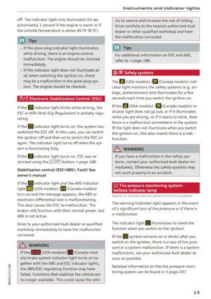 15
15 16
16 17
17 18
18 19
19 20
20 21
21 22
22 23
23 24
24 25
25 26
26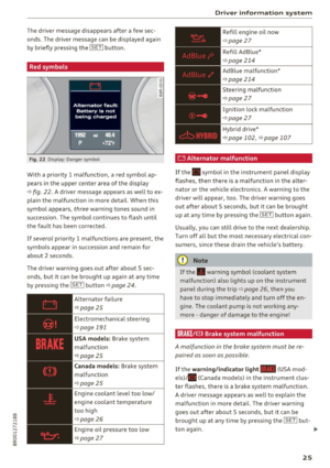 27
27 28
28 29
29 30
30 31
31 32
32 33
33 34
34 35
35 36
36 37
37 38
38 39
39 40
40 41
41 42
42 43
43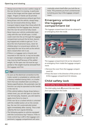 44
44 45
45 46
46 47
47 48
48 49
49 50
50 51
51 52
52 53
53 54
54 55
55 56
56 57
57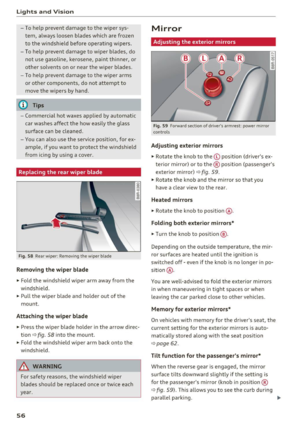 58
58 59
59 60
60 61
61 62
62 63
63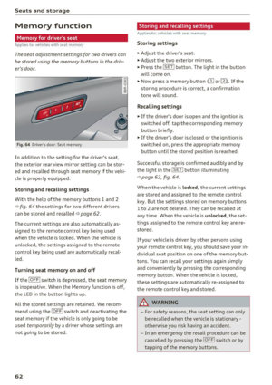 64
64 65
65 66
66 67
67 68
68 69
69 70
70 71
71 72
72 73
73 74
74 75
75 76
76 77
77 78
78 79
79 80
80 81
81 82
82 83
83 84
84 85
85 86
86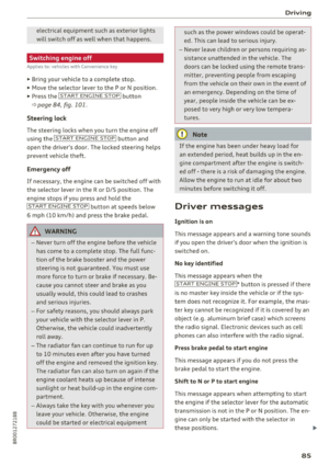 87
87 88
88 89
89 90
90 91
91 92
92 93
93 94
94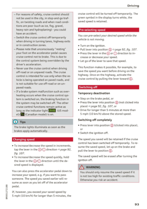 95
95 96
96 97
97 98
98 99
99 100
100 101
101 102
102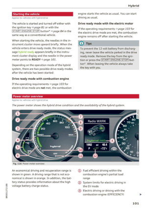 103
103 104
104 105
105 106
106 107
107 108
108 109
109 110
110 111
111 112
112 113
113 114
114 115
115 116
116 117
117 118
118 119
119 120
120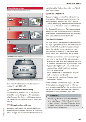 121
121 122
122 123
123 124
124 125
125 126
126 127
127 128
128 129
129 130
130 131
131 132
132 133
133 134
134 135
135 136
136 137
137 138
138 139
139 140
140 141
141 142
142 143
143 144
144 145
145 146
146 147
147 148
148 149
149 150
150 151
151 152
152 153
153 154
154 155
155 156
156 157
157 158
158 159
159 160
160 161
161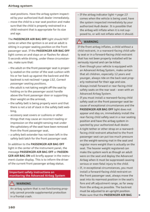 162
162 163
163 164
164 165
165 166
166 167
167 168
168 169
169 170
170 171
171 172
172 173
173 174
174 175
175 176
176 177
177 178
178 179
179 180
180 181
181 182
182 183
183 184
184 185
185 186
186 187
187 188
188 189
189 190
190 191
191 192
192 193
193 194
194 195
195 196
196 197
197 198
198 199
199 200
200 201
201 202
202 203
203 204
204 205
205 206
206 207
207 208
208 209
209 210
210 211
211 212
212 213
213 214
214 215
215 216
216 217
217 218
218 219
219 220
220 221
221 222
222 223
223 224
224 225
225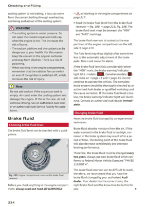 226
226 227
227 228
228 229
229 230
230 231
231 232
232 233
233 234
234 235
235 236
236 237
237 238
238 239
239 240
240 241
241 242
242 243
243 244
244 245
245 246
246 247
247 248
248 249
249 250
250 251
251 252
252 253
253 254
254 255
255 256
256 257
257 258
258 259
259 260
260 261
261 262
262 263
263 264
264 265
265 266
266 267
267 268
268 269
269 270
270 271
271 272
272 273
273 274
274 275
275 276
276 277
277 278
278 279
279 280
280 281
281 282
282 283
283 284
284 285
285 286
286 287
287 288
288 289
289 290
290 291
291 292
292 293
293 294
294 295
295