Page 81 of 116

156 || 157
HANDLING THE UNEXPECTEDHANDLING THE UNEXPECTED
HANDLING THE UNEXPECTED
Learn about what to do in critical or emergency situations.
Keyless Access Remote Battery Strength
If the battery life in your keyless access remote is weak, a
message appears in the driver information interface with
information on how to start the engine.
Touch the back of the keyless access remote to the ENGINE
START/STOP button while the indicator is flashing.
With the brake pedal pressed, press the ENGINE START/STOP
button within 10 seconds.
Emergency Power System Off
The ENGINE START/STOP button may be used to turn off the power system due to an
emergency situation even while driving. If you must turn off the power system, choose one of
the following operations:
Press and hold the ENGINE START/STOP button for two seconds,
OR
Firmly press the ENGINE START/STOP button three times.
Turning off the engine disables the power assist to the steering and braking systems. Thus,
it will require significantly more physical effort and time to steer and slow the vehicle.
Downshift gears and use both feet on the brake pedal, if necessary, to slow the vehicle and stop
immediately in a safe place.
Once the vehicle comes to a complete stop, the gear position automatically changes to (P) and
the power mode changes to VEHICLE OFF.
Do not press the button while driving unless it is absolutely necessary for the engine to be
switched off.
NOTICE
Page 82 of 116

158 || 159
HANDLING THE UNEXPECTEDHANDLING THE UNEXPECTED
Jump Starting
Turn off the power to electric devices, such as audio and lights. Turn off the power system, then
open the hood.
1.
Remove
the maintenance cover (see page 183), then slide
the terminal cover on your 12-volt battery’s (+) terminal
2.
Connect the first jumper
cable to your vehicle’s 12-volt
battery (+) terminal.
3.
Connect the other end of the first
jumper cable to the
booster battery (+) terminal. Use a 12-volt booster battery
only.
4.
Connect the second jumper cable to
the booster battery (-)
terminal.
5.
Connect the other end of the second
jumper cable to the
front frame (as shown). Do not connect this jumper cable to
any other part.
Booster Battery
Terminal Cover
A battery can explode if you do not follow the correct procedure, seriously injuring
anyone nearby.
Keep all sparks, open flames, and smoking materials away from the battery.
WARNING
n After the Engine Starts
Once your
vehicle’s engine has started, remove the jumper cables in the following order:
1.
Disconnect the jumper cable from
your vehicle’s ground.
2.
Disconnect the other end of the jumper cable
from the assisting vehicle’s (-) terminal.
3.
Disconnect the jumper cable from
the assisting vehicle’s (+) terminal.
4.
Disconnect the other end of the jumper cable
from your vehicle’s (+) terminal.
Have your vehicle inspected by a nearby service station or an authorized Acura NSX
dealer.
If your vehicle is connected to another vehicle, start the assisting vehicle’s engine and increase
its rpm slightly.
Attempt to start your vehicle’s engine. If it turns over slowly, make sure the jumper cables have
good metal-to-metal contact.
WARNING: Battery posts, terminals, and related accessories contain lead and lead compounds.
Wash your hands after handling.
Page 83 of 116

160 || 161
HANDLING THE UNEXPECTEDHANDLING THE UNEXPECTED
Overheating
If the temperature gauge needle is at the H mark, the engine suddenly loses power, or steam or
spray comes out from under the hatch, your engine is overheating.
Immediately park the vehicle in a safe place. Turn off all accessories and turn on the hazard
warning lights. Change the gear position to (P).
If no steam or spray is present: Keep the power system on and open the hatch.
If steam or spray is present: Turn off the power system and wait until it subsides. Then, open
the hatch.
Check that the cooling fan is operating and turn the power system off once the temperature
gauge needle comes down. If the cooling fan is not operating, immediately turn the power
system off.
Once the engine has cooled down, inspect the coolant level and
check the cooling system components for leaks. If the coolant
level in the reserve tank is low, or no coolant is in the tank, check
that the radiator is cool. Cover the reserve tank cap with a heavy
cloth and open the cap. Add coolant until it reaches the MAX
mark, and put the cap back on.
Reserve TankMAXMIN
Once the engine has cooled sufficiently, turn the power system on and check the temperature
gauge. If the temperature needle has gone down, resume driving. If it has not gone down,
contact an authorized Acura NSX dealer for repairs.
Steam and spray from an overheated engine can seriously scald you.
Do not open the hatch if steam is coming out.
WARNING
Removing the radiator cap while the engine is hot can cause the coolant to spray
out, seriously scalding you.
Always let the engine and radiator cool down before removing the radiator cap.
WARNING
Continuing to drive with the temperature gauge needle at the H mark may damage the engine.
NOTICE
Page 84 of 116

162 || 163
HANDLING THE UNEXPECTEDHANDLING THE UNEXPECTED
Emergency Towing
This vehicle requires flat bed towing. Call a professional towing service if you need to tow
your vehicle. The operator loads your vehicle on the back of a truck.
Trying to lift or tow your vehicle by the bumpers will cause serious damage. The bumpers are
not designed to support the vehicle’s weight.
Improper towing such as towing behind a motorhome or other motor vehicle can damage the
transmission.
NOTICE
Tire Pressure Monitoring System (TPMS)
Monitors the tire pressure while you are driving.
If your vehicle’s tire pressure becomes significantly low, the low
tire pressure indicator comes on and a message appears on the
multi-information display. Roll the right selector wheel on the
steering wheel to view the tire pressure monitor.
n What to Do
Stop your
vehicle in a safe place. Check the tire pressure and adjust the pressure to the
specified level. The specified tire pressure is on a label on the driver’s doorjamb.
Driving on an extremely underinflated tire can cause it to overheat. An overheated tire can
fail. Always inflate your tires to the specified pressure.
NOTICE
Page 85 of 116
 - Required Federal Explanation
Each tire, including
the spare (if provided), should be checked")
164 || 165
HANDLING THE UNEXPECTEDHANDLING THE UNEXPECTED
n Tire Pressure Monitoring System (TPMS) - Required Federal Explanation
Each tire, including
the spare (if provided), should be checked monthly when cold
and inflated to the inflation pressure recommended by the vehicle manufacturer
on the vehicle placard or tire inflation pressure label.
(If your vehicle has tires of a different size than the size indicated on the vehicle
placard or tire inflation pressure label, you should determine the proper tire
inflation pressure for those tires.)
As an added safety feature, your vehicle has been equipped with a tire
pressure monitoring system (TPMS) that illuminates a low tire pressure
telltale when one or more of your tires is significantly under-inflated.
Accordingly, when the low tire pressure telltale illuminates, you should stop and
check your tires as soon as possible, and inflate them to the proper pressure.
Driving on a significantly under-inflated tire causes the tire to overheat and can
lead to tire failure. Under-inflation also reduces fuel efficiency and tire tread life,
and may affect the vehicle’s handling and stopping ability.
Please note that the TPMS is not a substitute for proper tire maintenance, and it is
the driver’s responsibility to maintain correct tire pressure, even if under-inflation
has not reached the level to trigger illumination of the TPMS low tire pressure
telltale. Your vehicle has also been equipped with a TPMS malfunction indicator to indicate
when the system is not operating properly. The TPMS malfunction indicator
is combined with the low tire pressure telltale. When the system detects a
malfunction, the telltale will flash for approximately one minute and then remain
continuously illuminated. This sequence will continue upon subsequent vehicle
start-ups as long as the malfunction exists.
When the malfunction indicator is illuminated, the system may not be able to
detect or signal low tire pressure as intended.
TPMS malfunctions may occur for a variety of reasons, including the installation of
replacement or alternate tires or wheels on the vehicle that prevent the TPMS from
functioning properly.
Always check the TPMS malfunction telltale after replacing one or more tires
or wheels on your vehicle to ensure that the replacement or alternate tires and
wheels allow the TPMS to continue to function properly.
Page 86 of 116

166 || 167
HANDLING THE UNEXPECTEDHANDLING THE UNEXPECTED
Tire Repair Kit
If a tire has a small puncture, you can use the tire repair kit to temporarily repair it. The puncture
must be smaller than 3/16-inch (4 mm) and not in the tire sidewall. Go to a authorized Acura
NSX dealer to have the full-size tire permanently repaired or replaced.
n
Before Repairing
the Tire
•
Park the v
ehicle on a firm, level, and non-slippery surface.
•
Make sure the
vehicle is in Park (P), and apply the parking brake.
•
Turn on the hazard warning
lights, and turn the power system off. n
Getting Ready to R
epair the Tire
1. Open the hatch.
2.
Loosen the tool box tie-downs and
remove the tool box
lid.
3.
Take the kit out of the tool
box.
4.
Place the kit face up on
flat ground near the punctured
tire and away from traffic. Do not place the kit on its side.
Follow the instructions in the kit to repair the tire.Lid Tie Down
Tire Repair Kit
Do not use an unapproved puncture-repairing agent other than the one provided in the kit
that came with your vehicle. If a different agent is used, you may permanently damage the
tire pressure sensor.
NOTICE
Page 87 of 116
 and check
to see if any applicable f")
168 || 169
HANDLING THE UNEXPECTEDHANDLING THE UNEXPECTED
Fuse Locations
If any electrical devices are not working, set the power mode to VEHICLE OFF (LOCK) and check
to see if any applicable fuse is blown. Fuse locations are shown on the fuse box cover. Locate the
fuse by the fuse number and box cover number.
n
Hood Fuse Box A
Located near the
radiator. Push the tabs to open the box.
Fuses shown on next page.
Circuit Protected Amps
1
70A50A40A20A30A200A
2(50 A) 60 A
(6 0A )
(5 0A )
30 A
30 A
(4 0A )
30 A
30 A
3
(40A )30A(30 A)30A
4 (30 A)10
A
57.5A
610 A
77.5ALeft Headlight High Beam VFP2EPS
Cooling Fan
ABS/VSA Motor ABS/VSA FS R
AS F/B Main Main Fuse �
F/B Main 1
�
�
Left Electric Parking Brake Motor
Right Electric Parking Brake Motor
�
Heater Motor 2
Heater Motor 1 �
E-OP �
ADS
AMP
*
Parking Light IGPS PCS 8
Left Headlight Low Beam 10 A
9Right Headlight High Beam
10 10
A
Right Headlight Low Beam10 A
11IGPS Fan 7.5 A
12 FI Main15A
13FI Sub14 20
A
Back Up7.5A
15SBW ECU16 7.5 A
DBW 115A
17IG Coil15 A
18 DBW215A
19Parking Light & Headlight Main 20
A
20 Rear Defroste r
20A
21Front Washer 20A
22 ISC15A
23��
24 ACC/IG2 Main 10 A
2510 A
26 Daytime Running Lights
Horn10A
27Interior Lights 7.5 A
28 IGP215A
29Audio10 A
AmpsCircuit Protecte dCircuit Protected Amps
1
70A50A40A20A30A200A
2(50 A) 60 A
(6 0A )
(5 0A )
30 A
30 A
(4 0A )
30 A
30 A
3
(40A )30A(30 A)30A
4 (30 A)10
A
57.5A
610 A
77.5ALeft Headlight High Beam VFP2EPS
Cooling Fan
ABS/VSA Motor ABS/VSA FS R
AS F/B Main Main Fuse �
F/B Main 1
�
�
Left Electric Parking Brake Motor
Right Electric Parking Brake Motor
�
Heater Motor 2
Heater Motor 1 �
E-OP �
ADS
AMP
*
Parking Light IGPS PCS 8
Left Headlight Low Beam 10 A
9Right Headlight High Beam
10 10
A
Right Headlight Low Beam10 A
11IGPS Fan 7.5 A
12 FI Main15A
13FI Sub14 20
A
Back Up7.5A
15SBW ECU16 7.5 A
DBW 115A
17IG Coil15 A
18 DBW215A
19Parking Light & Headlight Main 20
A
20 Rear Defroste r
20A
21Front Washer 20A
22 ISC15A
23��
24 ACC/IG2 Main 10 A
2510 A
26 Daytime Running Lights
Horn10A
27Interior Lights 7.5 A
28 IGP215A
29Audio10 A
AmpsCircuit Protecte d
Page 88 of 116

170 || 171
HANDLING THE UNEXPECTEDHANDLING THE UNEXPECTED
n Hood Fuse Box B
Located near the 12-volt battery
. Remove the maintenance cover, then push the tabs to
open the box.
AmpsCircuit Protected
160 A�60A30A30A30A30A40A
230 A
320 A
47. 5A
5
6 7.
5A20 A
7
8 7.
5A10 A
9�
107. 5A
11
12 7.
5A
�13�
14 �
15�
16 �
1710A
SBW
�
F/B Main 2
Wiper
Passenger Power Window IG Main1
Driver Power Window ESB
IG Main2
IMA Moto r
BM S
Stop
Turbo W/ G
Hazard WA/
C/ P
�
AEV
FI-ECU Backup �
�
�
�
�
IMA Motor
n Driver’s Side Fuse Box
Located under the dashboard.
Circuit Protected Amps110A
215 A
37.5 A
4�
520 A
6
20 A
715 A
87.5 A
97.5 A
1010 A
1110 A
12�1310 A
147.5 A
15
(20A )
16
(7.5 A)
17(20A )
1810 A
19�
207.5 A
21
7.5 A
227.5 A
237.5 A
Passenger’s Door Handle Door LockSMART �
Front Accessory Power Socket
Fuel Pum p
MISS SO L
ENG
VSA/ABS SRS
Power System 2
�
Power System 1
Fuel Lid
Driver’s Power Seat Reclining *
�
Seat Heater *
Driver’s Door Handle �
Passenger’s Side Door Unlock
Daytime Running Lights
Key Lock
Air Conditionin g
24Feed Back IG1a 7.5A
25Instrument Panel Lights7.5A
26Power Lumbar Support *(7.5
A)
27Parking Lights7.5A
28Sub Main15 A29Meter10 A30DR27.5A
31Sub Fuel Pump15 A
32SR S10 A
33Passenger’s Side Door Lock 7.5A34Driver’s Door Lock7.5A
35Driver’s Door Unlock7.5A
36Driver’s Power Seat Sliding *(2
0A )
37
7.5A
Right Daytime Running
Light
38
7.5A39 Left Daytime Running LightFeed Back IG1b7.5A
40ACC7.5A
41��42��
AmpsCircuit Protecte d
Fuse Label
Circuit Protected Amps110A
215 A
37.5 A
4�
520 A
6
20 A
715 A
87.5 A
97.5 A
1010 A
1110 A
12�1310 A
147.5 A
15
(20A )
16
(7.5 A)
17(20A )
1810 A
19�
207.5 A
21
7.5 A
227.5 A
237.5 A
Passenger’s Door Handle Door LockSMART �
Front Accessory Power Socket
Fuel Pum p
MISS SO L
ENG
VSA/ABS SRS
Power System 2
�
Power System 1
Fuel Lid
Driver’s Power Seat Reclining *
�
Seat Heater *
Driver’s Door Handle �
Passenger’s Side Door Unlock
Daytime Running Lights
Key Lock
Air Conditionin g
24Feed Back IG1a 7.5A
25Instrument Panel Lights7.5A
26Power Lumbar Support *(7.5
A)
27Parking Lights7.5A
28Sub Main15 A29Meter10 A30DR27.5A
31Sub Fuel Pump15 A
32SR S10 A
33Passenger’s Side Door Lock 7.5A34Driver’s Door Lock7.5A
35Driver’s Door Unlock7.5A
36Driver’s Power Seat Sliding *(2
0A )
37
7.5A
Right Daytime Running
Light
38
7.5A39 Left Daytime Running LightFeed Back IG1b7.5A
40ACC7.5A
41��42��
AmpsCircuit Protecte d
*if equipped
 1
1 2
2 3
3 4
4 5
5 6
6 7
7 8
8 9
9 10
10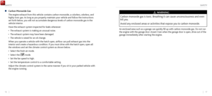 11
11 12
12 13
13 14
14 15
15 16
16 17
17 18
18 19
19 20
20 21
21 22
22 23
23 24
24 25
25 26
26 27
27 28
28 29
29 30
30 31
31 32
32 33
33 34
34 35
35 36
36 37
37 38
38 39
39 40
40 41
41 42
42 43
43 44
44 45
45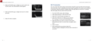 46
46 47
47 48
48 49
49 50
50 51
51 52
52 53
53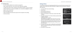 54
54 55
55 56
56 57
57 58
58 59
59 60
60 61
61 62
62 63
63 64
64 65
65 66
66 67
67 68
68 69
69 70
70 71
71 72
72 73
73 74
74 75
75 76
76 77
77 78
78 79
79 80
80 81
81 82
82 83
83 84
84 85
85 86
86 87
87 88
88 89
89 90
90 91
91 92
92 93
93 94
94 95
95 96
96 97
97 98
98 99
99 100
100 101
101 102
102 103
103 104
104 105
105 106
106 107
107 108
108 109
109 110
110 111
111 112
112 113
113 114
114 115
115