Page 153 of 184

Locking the door without locking cylindersFig. 178
Emergency locking: Left/right rear door
›
Open the corresponding back door remove the trim
A
» Fig. 178 .
›
Insert the key into the slot and turn in the direction of the arrow (spring-loa-
ded position).
›
Replace the cover
A
.
After closing, the door is locked.
Unlock the boot lid
Fig. 179
Unlocking the door
The boot lid can be unlocked manually from inside the vehicle.
›
Insert a screwdriver or similar tool into the recess in the trim » Fig. 179 as far
as the stop.
›
Unlock the lid by moving it in the direction of the arrow.
Selector lever-emergency unlockingFig. 180
Remove / release the selector lever
›
Firmly apply the handbrake.
›
With one hand on the edge of the cover, push in direction of arrow
1
» Fig. 180 .
›
At the same time lift the cover on the selector lever gaiter with the other
hand in direction of arrow
2
.
›
Press on the yellow plastic part in the direction of arrow
3
, simultaneously
press the lock button in the selector lever handle and put the lever in posi-
tion N.
If the selector lever is moved again to position P, it is once again blocked.
CAUTION
Make sure when lifting not to damage cover parts by the screwdriver in the
shift lever environment.
Replacing windscreen wiper blades
Introduction
This chapter contains information on the following subjects:
Replacing the windscreen wiper blades
152
Replacing the rear window wiper blade
152WARNINGReplace the windscreen wiper blades once or twice a year for safety rea-
sons.151Emergency equipment and self-help
Page 154 of 184

Replacing the windscreen wiper bladesFig. 181
Setting the service position for
the wiper arms
Fig. 182
Changing the windscreen wiper blade
Read and observe
on page 151 first.
Before replacing the windscreen wiper blades, close the bonnet and put the windscreen wiper arms into the service position.
Setting the service position
›
Switch the ignition on and off again.
›
Push the lever in the direction of arrow » Fig. 181 within 10 seconds and hold
for approximately 2 seconds.
Removing the wiper blade
›
Lift the wiper arm from the window in the direction of
1
» Fig. 182 .
›
Tilt the wiper blade to the stop in the same direction.
›
Grip the wiper arm and press securing latch
A
down in the direction of arrow
2
.
›
Remove the wiper blade in the direction of the arrow
3
.
Attaching the windscreen wiper blade›Slide the windscreen wiper blade in the opposite direction to arrow 3 until it
locks into place. Check that the windscreen wiper blade is correctly attached.›
Fold the windscreen wiper arm back to the windscreen.
›
Turn on the ignition and press the lever in the direction of the arrow
» Fig. 181 .
The windscreen wiper arms move into the home position.
Replacing the rear window wiper blade
Fig. 183
Changing the rear window wiper blade
Read and observe
on page 151 first.
Removing the wiper blade
›
Lift the wiper arm » page 152 from the window in the direction of arrow
1
» Fig. 183.
›
Tilt the wiper blade to the stop in the same direction.
›
Grip the wiper arm and press securing latch
A
down in the direction of arrow
2
.
›
Remove the wiper blade in the direction of the arrow
3
.
Attaching the windscreen wiper blade
›
Slide the windscreen wiper blade in the opposite direction to arrow
3
until it
locks into place. Check that the windscreen wiper blade is correctly attached.
›
Fold the windscreen wiper arm back to the windscreen.
152Do-it-yourself
Page 155 of 184

Fuses and light bulbs
Fuses
Introduction
Fig. 184
Blown fuse
This chapter contains information on the following subjects:
Fuses in the dashboard
153
Fuse arrangement in the dashboard
154
Fuses in the engine compartment
155
Fuse arrangement in the engine compartment
156
Individual electrical circuits are protected by fuses. A blown fuse is recognisa-
ble from the melted-through metal strip » Fig. 184.
WARNINGAlways read and observe the warning notes before completing any work in
the engine compartment » page 128, Engine compartment .
CAUTION
■
Replace the faulty fuse with a new one of the same amperage.■If a newly inserted fuse again blows after a short time, then seek assistance
from a specialist garage.■
“Do not repair” the fuses and do not replace them with stronger fuses - dan-
ger of fire and damage to another electrical system.
Note
■ We recommend always carrying replacement fuses in the vehicle.■There can be several power-consuming devices for one fuse. Multiple fuses
may exist for a single power-consuming device.Fuses in the dashboardFig. 185
Remove the fuse box cover.
Read and observe and on page 153 first.
The fuses are located on the bottom of the dash panel behind a cover.
Replacing fuses
›
Remove the ignition key, turn off the lights and all electrical consumers.
›
Remove the cover of the fuse box » Fig. 185 in the direction of the arrow.
›
Remove the plastic clip from the holder in the fuse box cover.
›
Use the clip to pull the fuse out, then insert a new fuse.
›
Replace the bracket at the original position.
›
Insert the top edge of the cover into the dash panel first.
›
Push the lower edge of the cover in the region
A
.
153Fuses and light bulbs
Page 156 of 184

Fuse arrangement in the dashboardFig. 186
Fuses: LHD / RHD
Read and observe
and on page 153 first.
No.Power consumer1Light - left2Central locking, windscreen and rear window washer system (only
with KESSY or heated windscreen)3Ignition4Light - right5Power windows - driver6Interior lighting7Horn8Towing hitch - left light
9
Operating lever beneath the steering wheel, engine control unit (on-
ly without KESSY), automatic gearbox (only without KESSY), auto-
matic gearbox (only without KESSY), ESC (only without KESSY), tow-
ing equipment (only without KESSY), power steering (only without
KESSY)10Power windows - rear left11Headlight cleaning system12Infotainment display13Voltage stabiliser for taxi vehicles14Operating lever under the steering wheel, light switch, ignition key
removal lock (automatic gearbox), headlight flasher, SmartGate, rain
sensor, rear view cameraNo.Power consumer15Air conditioning, automatic transmission, diagnostic connector, heat-
ed windscreen16Instrument cluster, emergency call17Anti-theft alarm, horn18Rear seat heating19Not assigned20Not assigned21Not assigned22Windscreen and rear window washer system (without KESSY or
without heated windscreen)23Heated front seats24Blower fan for air conditioning system, heating, air conditioning,
heating25Not assigned26Heated front seats27Rear window wiper28Not assigned29airbag30Electric windows, reverse light switches, air conditioning system,
Park Assist, exterior mirror settings, power feed for centre button
strip, power feed for side button strip, interior mirror31Fuel pump, radiator fan, cruise control, windscreen and rear window
washer, light switch32Diagnostic connector, headlight levelling, control lever under the
steering wheel, interior lighting, voltage stabiliser for taxi vehicles33Engine starting, clutch pedal switch34Heated windscreen washer jets35Not assigned36Not assigned37Radar38Not assigned39Electrical auxiliary heating system40Not assigned 154Do-it-yourself
Page 157 of 184

No.Power consumer41Rear window heater42Power windows - front passenger43Trailer device - electrical outlet44Cigarette lighter, 12-volt socket in the interior, 12-volt socket in the
luggage compartment45Power windows - rear right46Front and rear window washer, operating lever under the steering
wheel47Trailer device - electrical outlet48Towing hitch - right light49Fuel pump50Infotainment51Heating of the external mirror52KESSY53Steering lock (KESSY)54ABS or ESC55Not assigned56Not assigned57Not assigned58Rear seat heating59Not assigned
Fuses in the engine compartment
Fig. 187
Cover for the fuse box - variant 1
Fig. 188
Cover for the fuse box - variant 2
Read and observe
and on page 153 first.
Replacing fuses
›
Remove the ignition key, turn off the lights and all electrical consumers.
›
Press the cover in the direction of arrow
1
» Fig. 187 or » Fig. 188 and re-
move the cover in the direction of arrow
2
.
›
Remove the plastic clip from the holder on the cover of the fuse box in the
dashboard.
›
Replace the defective fuse.
›
Replace the cover, push the lock buttons of the cover together and lock.
›
Replace the bracket at the original position.
CAUTION
The cover of the fuse box in the engine compartment must always be used
correctly, otherwise water may penetrate into the fuse box – there is a danger
of damage to the vehicle!155Fuses and light bulbs
Page 158 of 184

Fuse arrangement in the engine compartmentFig. 189
Fuses
Read and observe and on page 153 first.
No.Power consumer1Radiator fan2Glow plug system3ABS or ESC4Additional electrical heating, heated windscreen5Additional electrical heating, heated windscreen6Automatic gearbox7Engine control system8Windscreen wipers9Battery data module10ABS or ESC11Not assigned12Injectors, valve for fuel metering, control valve for fuel pressure13Brake pedal switch14Fuel pump, radiator fan, cooling pump, pump intercooling15Engine control system, voltage stabiliser for taxi vehicles16Starter17Engine control system18Additional electric heater, valve for intake manifold, wastegate, oil
temperature, valve for activated charcoal filter, valve for oil pressure
controlNo.Power consumer19Lambda probe20Glow plug system, crankcase ventilation heater
Bulbs
Introduction
This chapter contains information on the following subjects:
Bulb arrangement in the front headlights
157
Replacing the bulb for the side light (Halogen headlights)
157
Changing the bulb for main beam, separate daytime running lights, and
parking light
157
Changing the bulb for the front turn signal light
158
Changing light bulbs for fog lights
159
Changing the bulb for the licence plate light
159
Removing/installing taillights
160
Replacing the bulbs in the taillight assembly
160
We recommend having bulbs replaced by a specialist garage or seeking other
expert help in the event of any uncertainties.
▶ Switch off the ignition and all of the lights before replacing a bulb.
▶ Faulty bulbs must only be replaced with the same type of bulbs. The designa-
tion is located on the light socket or the glass bulb.
We recommend having the headlight settings checked by a specialist garage after replacing a bulb in the low, high or fog beam.
In the case of failure of a Xenon gas discharge bulb or an LED diode, visit a
specialist garage.
WARNING■ Always read and observe the warning notes before completing any work
in the engine compartment » page 128.■
Accidents can be caused if the road in front of the vehicle is not suffi-
ciently illuminated and the vehicle cannot or can only be seen with difficul-
ty by other road users.
156Do-it-yourself
Page 159 of 184
■H7 and H15 bulbs are pressurised and may burst when changing the bulb -
risk of injury! We therefore recommended wearing gloves and safety
glasses when changing a bulb.■
Do not")
WARNING (Continued)■H7 and H15 bulbs are pressurised and may burst when changing the bulb -
risk of injury! We therefore recommended wearing gloves and safety
glasses when changing a bulb.■
Do not carry out any work on the Xenon gas discharge lamps - risk of
death!
CAUTION
■ Do not take hold of the glass bulb with naked fingers (even the smallest
amount of dirt reduces the working life of the light bulb). Use a clean cloth,
napkin, or similar.■
The cap of the filament bulb must always be seated correctly in the head-
light, otherwise this may allow water and debris to enter the headlight - risk of
damage to the headlights.
Note
■ This Owner's Manual only describes the replacement of bulbs where it is pos-
sible to replace the bulbs on your own without any complications arising. Other
bulbs must be replaced by a specialist garage.■
We recommend that a box of replacement bulbs always be carried in the ve-
hicle.
Bulb arrangement in the front headlights
Fig. 190
Left headlight
Read and observe and on page 156 first.
Bulb arrangement » Fig. 190
Low beam or low beam with Xenon gas discharge lamp
Main beam, separate daytime running lights, and parking light
Turn signal light (at the front)
ABCReplacing the bulb for the side light (Halogen headlights)Fig. 191
Changing the bulb for the low beam
Read and observe
and on page 156 first.
›
Remove the protective cap
A
» Fig. 190 on page 157 .
›
Remove the socket with the bulb by jiggling it out in the direction of arrow
1
» Fig. 191 .
›
Remove the connector.
›
Insert the connector with the new bulb in the direction of arrow
2
so that
the fixing lug
A
fits the bulb into the recess on the reflector.
›
Attach the connector.
›
Fit the protective cap
A
» Fig. 190 on page 157 .
Changing the bulb for main beam, separate daytime running
lights, and parking light
Fig. 192
Replacing the bulb for main
beam and separate daytime run-
ning lights
157Fuses and light bulbs
Page 160 of 184

Fig. 193
Change the light bulb for the parking light
Read and observe
and on page 156 first.
Replacing the bulb for main beam and separate daytime running lights
›
Remove the protective cap
B
» Fig. 190 on page 157 .
›
Pull the holder until it stops in the arrow direction
1
» Fig. 192 .
›
Remove the socket with the bulb in the direction of arrow
2
.
›
Change the bulb in the socket.
›
Insert the socket with the new bulb into the headlight in the opposite direc-
tion to the arrow
2
.
›
Turn the socket with the new bulb in the opposite direction to the arrow
1
until it stops.
›
Fit protective cap
B
» Fig. 190 on page 157 Insert.
Remove / insert the bulb for parking light
›
Remove the protective cap
B
» Fig. 190 on page 157 .
›
Remove the bulb holder with the bulb by jiggling it out in the direction of the
arrow
1
» Fig. 193 .
›
Grasp the pedestal with the light bulb in the region
A
.
›
Remove the faulty bulb from the holder in the direction of the arrow
2
.
›
Insert a new bulb in the bulb holder up to the stop.
›
Replace the bulb holder in the headlamp with the bulb.
›
Fit protective cap
B
» Fig. 190 on page 157 Insert.
Changing the bulb for the front turn signal lightFig. 194
Changing the bulb for the front
turn signal light
Read and observe and on page 156 first.
›
Turn the socket with the bulb in the direction of arrow
1
» Fig. 194 .
›
Remove the socket with the bulb in the direction of arrow
2
.
›
Change the bulb in the socket.
›
Insert the socket with the new bulb into the headlight in the opposite direc-
tion to the arrow
2
.
›
Turn the socket with the new bulb in the opposite direction to the arrow
1
until it stops.
158Do-it-yourself
 1
1 2
2 3
3 4
4 5
5 6
6 7
7 8
8 9
9 10
10 11
11 12
12 13
13 14
14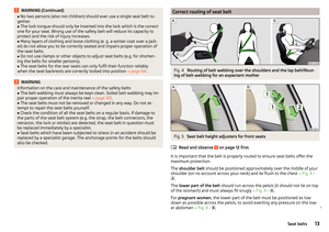 15
15 16
16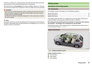 17
17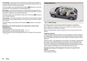 18
18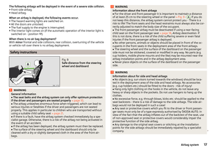 19
19 20
20 21
21 22
22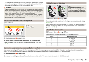 23
23 24
24 25
25 26
26 27
27 28
28 29
29 30
30 31
31 32
32 33
33 34
34 35
35 36
36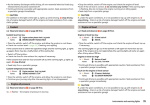 37
37 38
38 39
39 40
40 41
41 42
42 43
43 44
44 45
45 46
46 47
47 48
48 49
49 50
50 51
51 52
52 53
53 54
54 55
55 56
56 57
57 58
58 59
59 60
60 61
61 62
62 63
63 64
64 65
65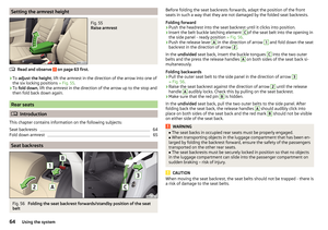 66
66 67
67 68
68 69
69 70
70 71
71 72
72 73
73 74
74 75
75 76
76 77
77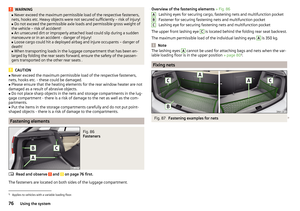 78
78 79
79 80
80 81
81 82
82 83
83 84
84 85
85 86
86 87
87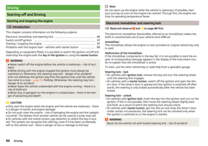 88
88 89
89 90
90 91
91 92
92 93
93 94
94 95
95 96
96 97
97 98
98 99
99 100
100 101
101 102
102 103
103 104
104 105
105 106
106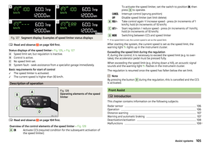 107
107 108
108 109
109 110
110 111
111 112
112 113
113 114
114 115
115 116
116 117
117 118
118 119
119 120
120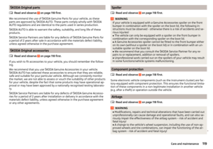 121
121 122
122 123
123 124
124 125
125 126
126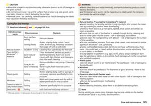 127
127 128
128 129
129 130
130 131
131 132
132 133
133 134
134 135
135 136
136 137
137 138
138 139
139 140
140 141
141 142
142 143
143 144
144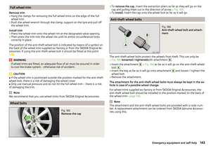 145
145 146
146 147
147 148
148 149
149 150
150 151
151 152
152 153
153 154
154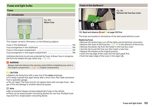 155
155 156
156 157
157 158
158 159
159 160
160 161
161 162
162 163
163 164
164 165
165 166
166 167
167 168
168 169
169 170
170 171
171 172
172 173
173 174
174 175
175 176
176 177
177 178
178 179
179 180
180 181
181 182
182 183
183