Page 113 of 184

Towing device and trailer
Hitch
Introduction
This chapter contains information on the following subjects:
Description
111
Adjusting the ready position
112
Check the setting of the standby position
112
Assembling the tow bar – Step 1
113
Assembling the tow bar – Step 2
113
Check proper fitting
114
Removing the tow bar – Step 1
114
Removing the tow bar – Step 2
114
Vertical load with mounted accessories
115
The maximum trailer nose weight when towing a trailer is 50 kg. Other infor-
mation (e.g. on the nameplate of the trailer device) provide only about the test
values of the device information.
WARNING■ Check that the tow bar is seated correctly and is secured in the mounting
recess before the start of every journey.■
When the ball rod is not used and properly secured in the receiving shaft,
this could be damaged or incomplete and must not be used - risk of acci-
dent.
■
Do not modify or adapt the towing device in any way.
■
Keep the mounting recess of the towing equipment clean at all times.
Such dirt prevents the ball head from being attached securely.
DescriptionFig. 135
Carrier for the towing device / tow bar
Read and observe
on page 111 first.
The ball rod is detachable and is located in the stowage compartment for the spare / emergency wheel.
Support for the towing device and tow bar » Fig. 135
Cap
Mounting recess
Protective cap
Locking ball
Centering
Hand wheel
Key
Lock cap
Red marking on the hand wheel
Tow bar
Green marking on the hand wheel
White marking on tow bar
123456789101112111Towing device and trailer
Page 114 of 184

Adjusting the ready positionFig. 136
Remove cap from the lock / insert key into the lock
Fig. 137
Setting the ready position
Read and observe
on page 111 first.
The tow bar must be set prior to installation to the standby position
» page 112 , Check the setting of the standby position .
›
Grip the tow bar below the protective cap.
›
Remove the cover
A
from the lock in the direction of the arrow
1
» Fig. 136 .
›
Insert the key into the lock
B
in the direction of arrow
2,
so that the arrow
on the key symbol
shows.
›
Turn the key
B
to the stop in the direction of arrow
3,
so that the arrow on
the key symbol shows
» Fig. 137 .
›
Pull the hand wheel
C
in the direction of the arrow
4
and turn in the direc-
tion of the arrow
5
to the stop. The hand wheel
C
remains locked in this
position.
Check the setting of the standby positionFig. 138
Ready position
Read and observe
on page 111 first.
Correctly adjusted standby position » Fig. 138
The key
A
is in the unlocked position - the arrow on the key points to the
symbol .
The locking ball
B
can be pushed fully into the tow bar.
The red marking
C
on the hand wheel points to the white marking on the
ball bar.
There is a clear gap of approx. 4 mm
D
between the hand wheel and the
tow bar.
When in the ready position, the key cannot be removed from the lock. The ball
bar is thus set ready for installation.
112Driving
Page 115 of 184

Assembling the tow bar – Step 1Fig. 139
Remove cap for receiving shaft / use ball bar
Read and observe
on page 111 first.
The tow bar must be set to the standby position » page 112, Check the setting
of the standby position . If this is not in the standby position, then it must be
set to the standby position » page 112, Adjusting the ready position .
›
To prepare for the installation , remove the cap for the receiving shaft
A
in
the direction of arrow
1
» Fig. 139 .
›
To install , hold the ball rod from underneath » Fig. 139 .
›
Push the ball rod into the receiving shaft in the direction of arrow
2
until it
stops. The ball rod must audibly snap into place » .
The hand wheel
B
rotates back automatically and rests on the ball rod » .
WARNINGDo not hold the hand wheel with your hand when attaching the ball bar -
there is a risk of finger injury.Assembling the tow bar – Step 2Fig. 140
Secure the lock and remove key / place cap on lock
Read and observe
on page 111 first.
›
First perform step 1 of the tow bar assembly » page 113.
›
Turn the key
A
in the direction of arrow
1,
so that the arrow on the key
symbol
» Fig. 140 shows.
›
Remove the key in the direction of the arrow
2
.
›
Fit the cap
B
on the lock in the direction of the arrow
3
.
›
Check that the ball rod is securely attached » page 114.
WARNINGAfter fitting the tow bar, always secure the lock and remove the key. The
tow bar must not be operated with the key inserted.113Towing device and trailer
Page 116 of 184

Check proper fittingFig. 141
Correctly secured ball head
Read and observe on page 111 first.
Correctly secured ball rod » Fig. 141
The tow bar does not come out of the mounting recess even after heavy
“shaking”.
The green marking
A
on the hand wheel points to the white marking on
the tow bar.
The steering wheel is tight against the ball rod.
The lock is locked and the key is removed.
The cap
B
is on the lock.
Removing the tow bar – Step 1
Fig. 142
Remove cap from the lock / insert key into the lock
Fig. 143
Unlock lock
Read and observe on page 111 first.
No trailer or other accessory is connected to the tow bar. We recommend put- ting the protective cover onto the ball head before removing the tow bar.
›
Remove the cover
A
from the lock in the direction of the arrow
1
» Fig. 142 .
›
Insert the key into the lock
B
in the direction of arrow
2,
so that the arrow
on the key symbol shows.
›
Turn the key
B
in the direction of arrow
3,
so that the arrow on the key
symbol
» Fig. 143 shows.
Removing the tow bar – Step 2
Fig. 144
Release tow bar
Read and observe on page 111 first.
Removing
›
Grasp the ball bar from below » Fig. 144 .
›
Pull the hand wheel
A
in the direction of the arrow
1
.
›
Pull the steering wheel until it stops in the direction of arrow
2
. Hold in this
position.
114Driving
Page 117 of 184

›Remove the tow bar from the mounting recess downwards and in the direc-
tion of the arrow 3. At the same time, the ball rod latches into the ready po-
sition and is therefore ready to be re-fitted.
After removing the ball rod, insert the cap for the receiving shaft A
against
the direction of arrow
1
» Fig. 139 on page 113 .
If the hand wheel
A
is not turned all the way to the stop, then it will return to
its initial position when the tow bar is removed and will rest on the tow bar
and not engage into the ready position. The ball head then needs to be
brought into this position before the next time it is fitted » page 112, Adjusting
the ready position .
The ball rod must be cleaned before storing in the box with the vehicle tool
always.
WARNINGNever allow the tow bar to remain unsecured in the boot. This could cause
damage to the boot upon sudden braking, and could put the safety of the
occupants at risk.
Vertical load with mounted accessories
Fig. 145
Representation of the maximum
length of the mounted accesso-
ries and the permissible total
weight of the accessory depend-
ing on the load centre of gravity
Read and observe on page 111 first.
When using the accessories (e.g. bicycle carrier), the maximum length and the
permissible total weight including load must be considered.
The maximum length of the mounted accessories (from the ball of the towing
device) is 70 cm » Fig. 145 .
The total permitted weight of the accessories including load changes with in-
creasing distance of the load centre of gravity from the ball head of the towing
device.
Distance of the centre of gravity of the load from the ball headPermissible total weight of the ac- cessory, including load0 cm50 kg30 cm50 kg60 cm25 kg70 cm0 kg
CAUTION
Never exceed the permissible total weight of the accessories incl. load and
maximum length of the accessories - risk of damage to the towing device.
Note
We recommend that you use accessories from ŠKODA Original Accessories.
Using the towing device
Trailer (accessory) connect and disconnect
Fig. 146
Swivel out the 13-pin power
socket, safety eyelet
Connect and disconnect
›
Install the ball rod and remove the protective cap
3
» Fig. 135 on page 111 .
›
Place the trailer (the accessory) onto the ball head.
›
Grip the 13-pin socket on the handle
A
and swing out in the direction of the
arrow » Fig. 146 .
›
Insert the trailer / accessory cable into the 13-pin socket. (If the trailer / ac-
cessories have a 7-pin connector, use a corresponding reduction piece from
the ŠKODA Original Accessories).
›
Suspend the breakaway cable of the trailer at the safety eyelet
B
(the
breakaway cable must sag in all trailer settings in view of the vehicle).
Uncoupling takes place in reverse order.
115Towing device and trailer
Page 118 of 184

Exterior mirrors
You should have additional exterior mirrors fitted if you are not able to see the
traffic behind the trailer using the standard rear-view mirrors.
Headlights
The front of the vehicle may lift up when a trailer (accessory) is being towed
and the headlights may dazzle other road users. Set the range of the head-
lights » page 54 .
Power supply of the trailer / accessory power system
In the electrical connection between the vehicle and trailer (accessory), the
trailer (accessories) is supplied with power from the vehicle (with ignition
switched on and off).
With the engine switched off, the vehicle battery is discharged by the connec-
ted consumers.
At low charge state of the vehicle battery, the power supply to the trailer (ac-
cessories) is interrupted.WARNING■ An improperly connected electrical installation of the trailer (accessories)
may result in an accident or serious injury from electrical shock.■
Do not make any adjustments to the electrical installation of the vehicle
and the trailer (accessories) - risk of an accident or serious injury from elec-
trical shock.
WARNING (Continued)■ After the electrical connection between the vehicle and trailer (accessory)
the trailer / accessory lights should be checked for function.■
Never use the securing eye to tow - risk of accident!
CAUTION
■ An improperly connected electrical installation of the trailer (accessories) can
lead to the inoperability of the vehicle electronics.■
The total power consumption of all the connected consumers to the trailer
power supply must not exceed 350 watts, otherwise there is a risk of damage
to the electrical system of the vehicle.
Loading a trailer
Correct the tyre inflation pressure on the vehicle for “full load” » page 137.
Distribution of the cargo
Distribute the cargo in the trailer in such a way that heavy items are located as
close to the trailer axle as possible. Secure the load from slipping.
The distribution of the weight is very poor if your vehicle is unladen and the
trailer is laden. Nevertheless, maintain a particularly low speed if you cannot
avoid driving with this combination.
WARNINGA sliding cargo can significantly adversely affect stability and driving safety
- there is a risk of accident!
Trailer load
The permissible trailer load must not be exceeded under any circumstances.Permissible trailer loadEngineGearboxPermissible trailer load, braked (kg)Permissible trailer load, unbraked (kg)Gradients of up to 12 %Gradients of up to 8% a)1.2 l/66 kW TSIMG9001000580DSG90010005901.2 ltr./81 kW TSIMG110012005901.4 ltr./92 kW TSIDSG12001200600DSG (Green tec)12001200610
116Driving
Page 119 of 184
Permissible trailer load, unbraked (kg)Gradients of up to 12 %Gradients of up to 8%a)1.6 l./81 kW MPIMG10001100580AG100011006001.4 l/66 kW TDI CRMG100")
EngineGearboxPermissible trailer load, braked (kg)Permissible trailer load, unbraked (kg)Gradients of up to 12 %Gradients of up to 8%a)1.6 l./81 kW MPIMG10001100580AG100011006001.4 l/66 kW TDI CRMG10001100610DSG100011006201.6 l/85 kW TDI CRMG12001200630a)
Only valid for some countries.
WARNINGThe maximum vertical load and the maximum trailer load must not be ex-
ceeded - there is risk of accident!
Towing a trailer
Driving speed
For safety reasons, do not drive with the trailer any faster than 100 km/h
(when the towing vehicle is a passenger car of category M1) or 80 km/h (when
the towing vehicle is a truck of category N1).
Immediately reduce your speed as soon as even the slightest swaying of the
trailer is detected. Never attempt to stop the trailer from “swaying” by acceler-
ating.
Brakes
Apply the brakes in good time! If the trailer is fitted with a trailer brake, apply
the brakes gently at first, then brake firmly. This will avoid brake jolts resulting
from the trailer wheels locking.
On downhill sections shift down a gear in good time to also use the engine as
a brake.
WARNINGAlways drive particularly carefully with the trailer.
CAUTION
With frequent towing, the vehicle is excessively loaded so this must also be
checked between service intervals.Anti-theft alarm system
The alarm is triggered if, with a vehicle with activated anti-theft alarm (herein-
after only warning system), the electrical connection to the trailer (accessory)
is interrupted.
Always switch off the anti-theft alarm system before a trailer (accessory) is
coupled or uncoupled » page 49.
Conditions for including a trailer (accessory) in the anti-theft alarm system. The vehicle is factory-fitted with an anti-theft alarm system and a towing
device.
The trailer (accessory) is electrically connected to the towing vehicle by
means of the trailer socket.
The electrical system of the vehicle and trailer (accessory) is functional.
The vehicle is locked and the anti-theft alarm system is activated.
The trailer (accessory) is not equipped with LED taillights.117Towing device and trailer
Page 120 of 184

General Maintenance
Care and maintenance
Service work, adjustments and technical alterations
Introduction
This chapter contains information on the following subjects:
Vehicle operating under different weather conditions
118
Statutory checks
118
ŠKODA service partner
118
ŠKODA Original parts
119
ŠKODA Original accessories
119
Spoiler
119
Component protection
119
Airbags
119
Acceptance and recycling of used vehicles
120
The instructions and guidelines from ŠKODA AUTO must be observed when us-
ing accessories or carrying out any modifications, repairs or technical altera-
tions to your vehicle.
Adhering to these instructions and guidelines helps ensure road safety and
helps keep your vehicle in a good technical condition.
WARNING■ Adjustments, repairs and technical changes to the vehicle should only be
carried out by a specialist. Work carried out incorrectly (including work on
the electronic components and their software) can result in malfunctions -
there is a risk of accident and, potentially, increased wear on parts!■
We recommend that you use only ŠKODA Original Accessories and ŠKODA
Original Parts which have been expressly approved for use on your vehicle.
Reliability, safety and suitability for your vehicle are guaranteed with these.
■
Do not use any products which have not been approved by ŠKODA AUTO,
even though these may be products with a type approval or which have
been approved by a nationally recognised testing laboratory.
Vehicle operating under different weather conditions
Read and observe
on page 118 first.
If you would like to operate your vehicle in countries other than those with its
intended weather conditions, you should contact a ŠKODA Partner. He or she
will advise you if certain precautions need to be taken to ensure the full func-
tioning of the vehicle or to prevent damage (e.g. coolant, changing the battery
or similar).
Statutory checks
Read and observe
on page 118 first.
Many countries have legislation requiring the operational reliability, safety and,
where applicable, roadworthiness and/or exhaust gas properties of a vehicle
to be tested at regular intervals. These tests can be carried out by workshops
or testing stations that have been legally authorised for this purpose.
The ŠKODA Service partners can prepare your vehicle for the official inspec-
tions, so as to ensure that it passes.
Even if you want to take your vehicle to an officially approved test centre for
prior checking in preparation for a legally required test, we recommend that
you consult your ŠKODA Service Partner beforehand.
ŠKODA service partner
Read and observe
on page 118 first.
All ŠKODA service partners work according to the instructions and guidelines
from ŠKODA AUTO. All service and repair work is therefore carried out on time
and to the appropriate quality. Adhering to these guidelines and instructions
helps ensure road safety and helps keep your vehicle in a good technical con-
dition.
We therefore advise you to have all modifications, repairs and technical altera-
tions to your vehicle carried out by a ŠKODA Service Partner.
118General Maintenance
 1
1 2
2 3
3 4
4 5
5 6
6 7
7 8
8 9
9 10
10 11
11 12
12 13
13 14
14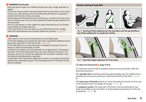 15
15 16
16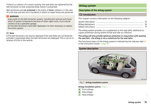 17
17 18
18 19
19 20
20 21
21 22
22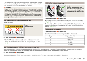 23
23 24
24 25
25 26
26 27
27 28
28 29
29 30
30 31
31 32
32 33
33 34
34 35
35 36
36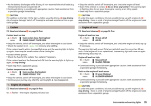 37
37 38
38 39
39 40
40 41
41 42
42 43
43 44
44 45
45 46
46 47
47 48
48 49
49 50
50 51
51 52
52 53
53 54
54 55
55 56
56 57
57 58
58 59
59 60
60 61
61 62
62 63
63 64
64 65
65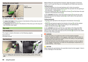 66
66 67
67 68
68 69
69 70
70 71
71 72
72 73
73 74
74 75
75 76
76 77
77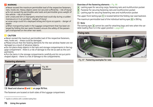 78
78 79
79 80
80 81
81 82
82 83
83 84
84 85
85 86
86 87
87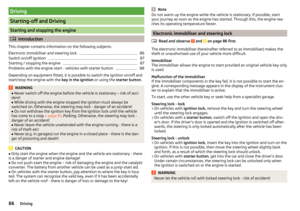 88
88 89
89 90
90 91
91 92
92 93
93 94
94 95
95 96
96 97
97 98
98 99
99 100
100 101
101 102
102 103
103 104
104 105
105 106
106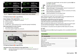 107
107 108
108 109
109 110
110 111
111 112
112 113
113 114
114 115
115 116
116 117
117 118
118 119
119 120
120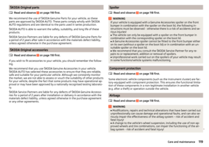 121
121 122
122 123
123 124
124 125
125 126
126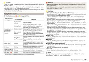 127
127 128
128 129
129 130
130 131
131 132
132 133
133 134
134 135
135 136
136 137
137 138
138 139
139 140
140 141
141 142
142 143
143 144
144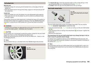 145
145 146
146 147
147 148
148 149
149 150
150 151
151 152
152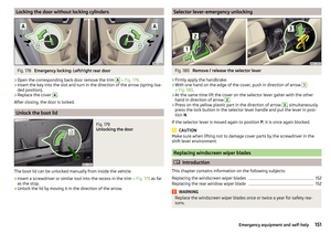 153
153 154
154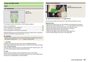 155
155 156
156 157
157 158
158 159
159 160
160 161
161 162
162 163
163 164
164 165
165 166
166 167
167 168
168 169
169 170
170 171
171 172
172 173
173 174
174 175
175 176
176 177
177 178
178 179
179 180
180 181
181 182
182 183
183