Page 81 of 184

Storage net bagFig. 94
Meshed pocket for storage
Read and observe and on page 76 first.
The meshed pocket for storage is located on the right-hand side of the boot» Fig. 94 .
The meshed pocket for storage is designed for storing small objects of up to
1.5 kg. in weight in total.
Cargo elements
Fig. 95
Remove cargo element: Version 1/version 2
Fig. 96
Remove cargo element: Version 3 / Mounting example of the car-
go using the cargo elements
Read and observe
and on page 76 first.
The cargo elements are designed for mounting and securing loads with a max-imum gross weight of 8 kg.
›
To use , remove the cargo elements in the direction of the arrows » Fig. 95
and » Fig. 96
.
›
Use the cargo elements to secure the load as close as possible to the rear
seats » Fig. 96
.
›
After use, secure the cargoelements in their original position.
Floor covering on both sides
Read and observe
and on page 76 first.
You can fit a double-sided floor covering in the luggage compartment. One
side is made of fabric, the other side is washable (suitable for transporting wet
or dirty items).
Class N1 vehicles
Read and observe
and on page 76 first.
In class N1 vehicles that are not fitted with a protective grille, a lashing set that
complies with the EN 12195 standard (1 - 4) must be used for fastening the
load.
79Transport of cargo
Page 82 of 184

Proper functioning of the electrical installation is essential for safe vehicle op-
eration. It is important to ensure that the electrical installation is not damaged
during the adjustment process or when the storage area is being loaded and
unloaded.
Variable loading floor in the luggage compartment (Estate)
Introduction
This chapter contains information on the following subjects:
Set in the upper / lower position
80
Removing/inserting
80
Folding up/down, “parking position”
81
Set in the upper / lower position
Fig. 97
Set the variable loading floor to the upper/lower position
The variable loading floor can be set to the upper or lower position as follows.
›
Lift the variable loading floor by the handle
A
in the direction of arrow
1
and partially move it in the direction of arrow
2
» Fig. 97 .
›To
set in the upper position , lift the variable loading floor in the front area
and position on the edge C.›
To set in the lower position , move the variable loading floor in the direction
of arrow
2
until it removes itself from the mounts
B
, and position the front
of the variable loading floor on the floor covering of the luggage compart-
ment.
›
Insert the variable loading floor in direction of arrow
3
until it stops (when
set in the lower position , the front region
D
must be raised) and position in
the direction of arrow
4
.
The area under the variable loading floor can be used to stow small objects.
The maximum permissible load of the variable loading floor in the upper posi-
tion is 75 kg. For the transport of heavy loads, adjust the variable loading floor
in the lower position.
Note
The variable loading floor cannot be set in the upper/lower position when the
luggage compartment cover is in the “parking position” » page 78.
Removing/inserting
Fig. 98
Remove variable loading floor
Removing
›
Lift the variable loading floor at handle
A
in the direction of arrow
1
until
its rear area is about 15 cm
B
below the edge of the cover » Fig. 98.
›
Remove the variable loading floor from the vehicle by moving it in the direc-
tion of arrow
2
.
Inserting
›
Grasp the variable loading floor at handle
A
» Fig. 98 .
›
Insert the variable loading floor, titled with the front area about 15 cm
B
be-
neath the edge of the cover, in the vehicle.
›
Then follow the same steps as when setting the upper position or the lower
position » page 80 .
80Using the system
Page 83 of 184

CAUTIONWhen removing or inserting the variable loading floor, a distance of 15 cm B» Fig. 98 underneath the edge of the cover must be maintained - risk of dam-
aging the boot lid seal.
Note
The variable loading floor cannot be placed in the vehicle when the luggage
compartment cover is in the “park position” » page 78.
Folding up/down, “parking position”
Fig. 99
Fold up/fold down the variable loading floor
Folding up
›
Lift the variable loading floor using the handle
A
in the direction of
1
. The
foldable corners
B
must be secured in the areas of
C
or
D
(“parking posi-
tion”) » Fig. 99 .
Folding down
›
On the folding corners
B
, press in the direction of arrow
2
, release this and
fold down the variable loading floor in the direction of arrow
3
.
WARNINGThe variable loading floor in the “parking position” restricts the driver's
view at the back.
Note
■ The variable loading floor can only be in set to the “parking position” when it
is in the lower position and the luggage compartment cover has been taken
out.■
If the variable loading floor is in the “parking position”, the “parking position”
on the luggage compartment cover cannot be set » page 78.
Transportation on the roof rackFig. 100
Attachment points
The attachment points
A
and
B
are located on both sides of the vehicle
» Fig. 100 .
The mounting and dismounting of the basic carrier is carried out according to
the instructions provided.
Roof load
The maximum permitted weight of the load incl. carriers is 75 kg.
WARNINGThe following instructions must be observed to aid road safety when trans- porting cargo on the roof rack.■
Always distribute the load on the roof rack evenly and secure properly
with suitable lashing straps or tensioning straps.
■
When transporting heavy objects or objects which take up a large area on
the roof rack system, handling of the car may change as a result of the dis-
placement of the centre of gravity. The style of driving and speed must
therefore be adapted to the current circumstances.
■
The permissible roof load, permissible axle loads and permissible total ve-
hicle weight must not be exceeded under any circumstance – risk of acci-
dent!
CAUTION
■ Ensure that the boot lid does not hit the roof load when opened.■Ensure the roof aerial is not impaired by the load being transported.
Note
We recommend that you use a roof rack from ŠKODA Original Accessories.81Transport of cargo
Page 84 of 184

Heating and ventilation
Heating, manual air conditioning system, Climatronic
Introduction
This chapter contains information on the following subjects:
Heating and manual air conditioning
82
Climatronic (automatic air conditioning)
83
Climatronic - automatic mode
84
Air distribution control
84
Air outlet vents
84
The heater heats and ventilates the vehicle interior. The air conditioning sys-
tem also cools and dehumidifies the vehicle interior.
The heating effect is dependent upon the coolant temperature, thus full heat
output only occurs when the engine has reached its operating temperature.
The cooling system works under the following conditions. The cooling system is switched on.
The engine is running.
The outside temperature is above 2 °C.
The blower is switched on.
When the cooling system is switched on, it prevents misting of the windscreen
and windows.
It is possible to boost the effectiveness of the cooling system by briefly acti-
vating the air recirculation system » page 84.
Health protection
To reduce health risks (e.g. common colds), the following instructions for the
use of the cooling system are to be observed. ▶ The difference between the outside temperature and the inside temperature
should not be greater than 5 °C.
▶ The cooling system should be turned off about 10 minutes before the end of
the journey.
▶ Once a year, a disinfection of the air conditioner is to be carried out by a spe-
cialist company.
WARNING■ The blower should always be on to prevent the windows from misting.
Otherwise there is a risk of accident.■
Under certain circumstances, air at a temperature of about 5 °C can flow
out of the vents when the cooling system is switched on.
Note
■ The air inlet in front of the windscreen must be free of e.g. ice, snow or
leaves to ensure that the heating and cooling system operates properly.■
After switching on the cooling Condensation from the evaporator of the air
conditioning may drip down and form a puddle below the vehicle. This is not a
leak!
■
If the coolant temperature is too high, the cooling system is switched off to
ensure that the engine cools down.
Heating and manual air conditioning
Fig. 101
Controls of the heating / air conditioning
Read and observe
on page 82 first.
Individual functions can be set or switched on by turning the dial or pressing the corresponding button » Fig. 101. When the function is switched on, the in-
dicator light in the button lights up.
Setting temperature
▶ Reduce the temperature /
Increase the temperature
Set the blower speed (Level 0: Fan off, level 4: high-speed)
Set the direction of the air outlet » page 84
Air flow to the windows
Air flow to the upper body
ABC82Using the system
Page 85 of 184

Air flow in the footwell
Air flow to the windows and the footwell
Switch recirculation on/off » page 84
Switch the cooling system on/off
Information on the cooling system
After pressing the button
» Fig. 101 , the warning light on the button lights
up, even if not all the conditions for the cooling system have been met. The
cooling system starts to work as soon as the following conditions have been
met » page 82 .
Note
To ensure adequate thermal comfort, during operation of the manual air condi-
tioning there could be an increase in the engine idle speed in some circum-
stances.
Climatronic (automatic air conditioning)
Fig. 102
Controls the Climatronic
Read and observe
on page 82 first.
Individual functions can be set or switched on by turning the dial or pressing the corresponding button » Fig. 102.
Setting temperature
▶ Reduce the temperature /
Increase the temperature
Selected temperature
Degrees Celsius or Fahrenheit
Automatic operation of the air conditioning system is switched on
Intensive air flow to the windscreen switched on
Direction of air flow
123456Recirculated air mode activated
Cooling system activated
Set blower speed
Set the blower speed (the set blower speed is indicated by the corre-
sponding number of segments in the display)
▶ Turn to the left: Decrease speed / switch off Climatronic
▶ Turn to the right: Increase speed
Interior temperature sensor Switching on/off the intensive windscreen air flow - when this function
is switched on, the warning light illuminates in the button
Switching automatic mode on » page 84
Switching the airflow to the windows on and off
Switching the airflow to the upper body on and off
Switching the airflow to the footwell on and off
Switch recirculation on/off » page 84
Switch the cooling system on/off
When this function is switched on, the corresponding icon appears in the dis-
play.
After the cooling system is switched off, only the ventilation function remains
active, whereby the lowest temperature that can be reached is the outside
temperature.
Setting temperature
In the range between 16 °C to 29 °C, an automatic temperature control takes
place.
At a temperature setting below 16 ° C, lights up in the temperature display,
the Climatronic functions with maximum cooling performance .
At a temperature setting above 29 °C, lights up in the temperature display,
the Climatronic functions with maximum heating output.
Switching between Celsius and Fahrenheit
Press the and
buttons simultaneously and hold for about 2 s, the dis-
play shows the desired unit (position 3
» Fig. 102 ).
CAUTION
Do not cover the interior temperature sensor 11 » Fig. 102 - the function of the
Climatronic could be affected. 789101183Heating and ventilation
Page 86 of 184

NoteIn order to ensure adequate thermal comfort, there may be an increase in en-
gine idle speed during operation of the Climatronic in some circumstances.
Climatronic - automatic mode
Read and observe
on page 82 first.
The automatic mode is used in order to maintain a constant temperature andto demist the windows in the interior of the car.
›
To switch on press the
button. The display shows
(pos.
4
» Fig. 102
on page 83 ).
›
To turn off , press any button for the air distribution or change the blower
speed. The temperature regulation is continued.
Air distribution control
Read and observe
on page 82 first.
The recirculation mode prevents contaminated outside air getting into the In-terior of the vehicle. In recirculated air mode air is sucked out of the interior of
the vehicle and then fed back into the interior.
›
To switch on/off , press the
symbol button repeatedly.
Heating and manual air conditioning system
If the air distribution control is set to position when the recirculation modes
is switched on, the recirculated-air mode is switched off. Recirculated air mode
can be switched on again from this setting by repeatedly pressing the symbol
button .
Climatronic
With the recirculated-air mode switched on the symbol appears in the dis-
play.
The symbol disappears from the display after turning off the air recircula-
tion.
If the humidity increases in the vehicle, an automatic shutdown of air recircula-
tion can occur.
WARNINGThe recirculation system cannot be switched on for a longer period of time,
because no fresh air is fed through from the outside. “Stale air” may result
in fatigue in the driver and occupants, reduce attention levels and also
cause the windows to mist up. As soon as windows mist up, turn on the re-
circulation system immediately - risk of accident!
CAUTION
We recommend not smoking in the vehicle when the recirculating air operation
is switched on. The smoke sucked from the interior is deposited on the evapo-
rator of the air conditioner. This produces a permanent odour when the air
conditioning system is operating which can only be eliminated through consid-
erable effort and expense (replacement of compressor).
Note
If recirculated air mode is switched on for around 15 minutes, the symbol
will begin to flash in the Climatronic display as a sign that the recirculated air
mode is switched on long-term. If the recirculated air mode is not switched off,
the symbol
flashes for around 5 minutes.
Air outlet vents
Fig. 103
Air outlet vents
Read and observe
on page 82 first.
The direction of airflow can be adjusted using the air outlet vents 3, 4
» Fig. 103 , the outlets can be opened and closed individually.
84Using the system
Page 87 of 184
The setting of the airflow direction is carried out by moving the adjustment el-
ement A » Fig. 103 in the desired direction.
Open/close›
Turn the regulator
B
upwards/downwards » Fig. 103.
Depending on the setting for air distribution, the air will flow from the follow-
ing air vents.
Set the direction of the air outletAir outlet vents » Fig. 1031. 2 . 41. 2 . 4 . 53 . 44 . 5
CAUTION
Do not cover the air vents - the air distribution could be compromised.85Heating and ventilation
Page 88 of 184

Driving
Starting-off and Driving
Starting and stopping the engine
Introduction
This chapter contains information on the following subjects:
Electronic immobiliser and steering lock
86
Switch on/off ignition
87
Starting / stopping the engine
87
Problems with the engine start - vehicles with starter button
88
Depending on equipment fitted, it is possible to switch the ignition on/off and
start/stop the engine with the key in the ignition or using the starter button .
WARNING■
Never switch off the engine before the vehicle is stationary – risk of acci-
dent!■
While driving with the engine stopped the ignition must always be
switched on. Otherwise, the steering may lock - danger of an accident!
■
Do not withdraw the ignition key from the ignition lock until the vehicle
has come to a stop » page 91, Parking . Otherwise, the steering may lock -
danger of an accident!
■
Never leave the vehicle unattended with the engine running - there is a
risk of theft etc!
■
Never (e.g. in garages) run the engine in a closed place - there is the dan-
ger of poisoning and death!
CAUTION
■ Only start the engine when the engine and the vehicle are stationary - there
is a danger of starter and engine damage!■
Do not push-start the engine – risk of damaging the engine and the catalytic
converter. The battery from another vehicle can be used as a jump-start aid.
■
On vehicles with the starter button, pay attention to where the key is loca-
ted. The system can recognize the valid key, even if it has been accidentally
left on the vehicle roof - there is danger of loss or damage to the key!
NoteDo not warm up the engine while the vehicle is stationary. If possible, start
your journey as soon as the engine has started. Through this, the engine rea-
ches its operating temperature faster.
Electronic immobiliser and steering lock
Read and observe
and on page 86 first.
The electronic immobiliser (hereinafter referred to as immobiliser) makes the
theft or unauthorised use of your vehicle more difficult.
Immobiliser
The immobiliser allows the engine to start provided an original vehicle key only
is used.
Malfunction of the immobiliser
If the immobiliser components in the key fail, it is not possible to start the en-
gine. A corresponding message appears in the display of the instrument clus-
ter to explain that the immobiliser is active.
To start, use the other vehicle key or seek help from a specialist garage.
Steering lock - lock
›
On vehicles with ignition lock, remove the key and turn the steering wheel
until the steering lock engages.
›
On vehicles with a starter button, switch off the ignition and open the driv-
er's door. If the driver's door is opened and the ignition is switched off after-
wards, the steering is only locked automatically after the vehicle has been
locked.
Steering lock - unlock
›
On vehicles with ignition lock, insert the key into the ignition and turn on the
ignition. If this is not possible, then move the steering wheel slightly back
and forth, as a result of which the steering lock should unlock.
›
On vehicles with starter button, get into the car and close the driver's door.
Under certain circumstances, the steering lock can be unlocked only when
the ignition is switched on or the engine is started.
WARNINGNever let the vehicle roll with locked steering lock - risk of accident!86Driving
 1
1 2
2 3
3 4
4 5
5 6
6 7
7 8
8 9
9 10
10 11
11 12
12 13
13 14
14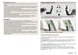 15
15 16
16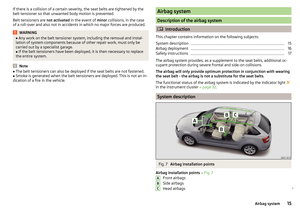 17
17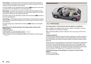 18
18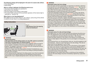 19
19 20
20 21
21 22
22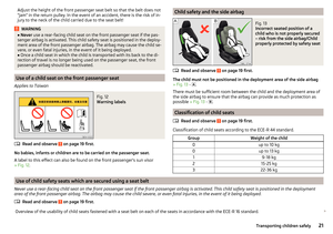 23
23 24
24 25
25 26
26 27
27 28
28 29
29 30
30 31
31 32
32 33
33 34
34 35
35 36
36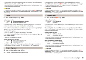 37
37 38
38 39
39 40
40 41
41 42
42 43
43 44
44 45
45 46
46 47
47 48
48 49
49 50
50 51
51 52
52 53
53 54
54 55
55 56
56 57
57 58
58 59
59 60
60 61
61 62
62 63
63 64
64 65
65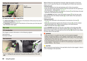 66
66 67
67 68
68 69
69 70
70 71
71 72
72 73
73 74
74 75
75 76
76 77
77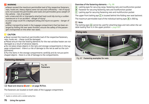 78
78 79
79 80
80 81
81 82
82 83
83 84
84 85
85 86
86 87
87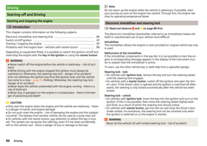 88
88 89
89 90
90 91
91 92
92 93
93 94
94 95
95 96
96 97
97 98
98 99
99 100
100 101
101 102
102 103
103 104
104 105
105 106
106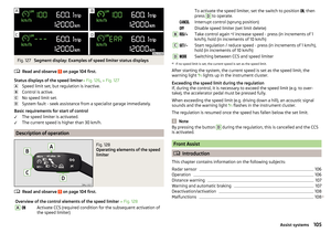 107
107 108
108 109
109 110
110 111
111 112
112 113
113 114
114 115
115 116
116 117
117 118
118 119
119 120
120 121
121 122
122 123
123 124
124 125
125 126
126 127
127 128
128 129
129 130
130 131
131 132
132 133
133 134
134 135
135 136
136 137
137 138
138 139
139 140
140 141
141 142
142 143
143 144
144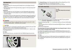 145
145 146
146 147
147 148
148 149
149 150
150 151
151 152
152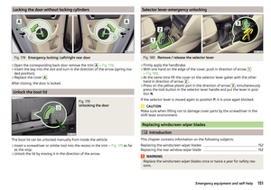 153
153 154
154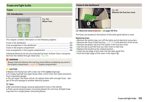 155
155 156
156 157
157 158
158 159
159 160
160 161
161 162
162 163
163 164
164 165
165 166
166 167
167 168
168 169
169 170
170 171
171 172
172 173
173 174
174 175
175 176
176 177
177 178
178 179
179 180
180 181
181 182
182 183
183