Page 145 of 184

Full wheel trim
Remove trim›
Hang the clamps for removing the full wheel trims on the edge of the full
wheel trim.
›
Push the wheel wrench through the clamp, support on the tyre and pull off
the wheel trim.
Install trim
›
Press the wheel trim onto the wheel rim at the designated valve opening.
›
Then press the trim into the wheel rim until its entire circumference locks
correctly in place.
The position of the anti-theft wheel bolt is indicated by means of a symbol on
the back of the wheel trim supplied ex-factory or from the ŠKODA Original Ac-
cessories. If using the anti-theft wheel bolt it should be fitted at this point
»
.
WARNINGIf wheel trims are fitted, an adequate flow of air must be assured in order
to cool the brake system - otherwise risk of accident.
CAUTION
■ If the wheel trim is positioned outside the position marked for the anti-theft
wheel bolt, there is a risk of damaging the wheel cover.■
Only use manual pressure and do not hit the full wheel trim – there is a risk
of damaging the trim.
Note
We recommend that you use wheel trims from ŠKODA Original Accessories.
Wheel bolts
Fig. 165
Remove the cap
› To
remove the cap , insert the extraction pliers as far as they will go on the
cap and pulling them out in the direction of arrow » Fig. 165.›
To install , insert the cap onto the wheel bolt as far as it will go.
Anti-theft wheel bolts
Fig. 166
Anti-theft wheel bolt and attach-
ment
The anti-theft wheel bolts protect the wheels from theft. This can only be » Fig. 166 loosened / tightened with attachment
B
.
›
Insert the attachment
B
» Fig. 166 as far as it will go on the anti-theft wheel
bolt
A
.
›
Insert the key as far as it will go onto attachment
B
and loosen / tighten the
wheel bolt.
›
Remove the attachment.
The attachment for the anti-theft wheel bolts must always be kept in the ve-
hicle in case of a possible wheel change.
For wheel trims supplied ex-factory or from ŠKODA Original Accessories, the
anti-theft wheel bolt should be installed in the position marked on the back of
the wheel trim » page 143.
Note
The attachment and the anti-theft wheel bolts are provided with a code num-
ber. A replacement attachment can be ordered from ŠKODA Genuine Accesso-
ries using this.143Emergency equipment and self-help
Page 146 of 184

Loosening/tightening wheel boltsFig. 167
Loosening the wheel bolts
›
Insert the wheel wrench onto the wheel bolt to the stop. Use the associated
attachment for the anti-theft wheel bolts » Fig. 166 on page 143 .
›
To loosen the screws , grasp the key end and turn the screw about one turn
rotation in the direction of the arrow » Fig. 167.
›
Totighten the screws , grasp the key end and turn the screw about against
the direction of the arrow » Fig. 167, until it is tight.
WARNINGIf it proves difficult to undo the bolts, carefully apply pressure to the end of
the wrench with your foot. Keep hold of the vehicle when doing so, and
make sure you keep your footing - danger of injury.
Raising the vehicle
Fig. 168
Jacking points for the jack
Fig. 169
Attach lifting jack
Before the vehicle is raised, please take note of the safety instructions »
.
In order to raise the vehicle, the jack from the tool kit is to be used. Position
the car jack at the jacking point closest to the flat tyre.
The jacking points are located on the lower sill » Fig. 168.
›
Position the base plate of the jack with its full area resting on level ground
and ensure that the jack will fit in the jacking point when raised » Fig. 169 -
.
›
Use the crank to raise the jack until its pawl covers the jacking
point » Fig. 169 -
.
›
Raise the vehicle until the wheel is a little off the floor.
WARNINGThe following instructions must be observed, otherwise there is risk of in-
jury.■
Ensure the vehicle cannot unexpectedly roll away.
■
Always ensure the base plate of the lifting jack cannot slip.
■ Place a wide and stable base material under the jack if on a loose surfa-
ces (e.g. gravel).
■ Place an anti-slip base material (e.g. a rubber mat) under the jack if on a
smooth surface (e.g. cobblestones).
■
Always raise the vehicle with the doors closed.
■
Never position any body parts (e.g. arms or legs) under the vehicle while
the vehicle is raised.
■
When the vehicle is raised, never start the engine.
CAUTION
It is important to ensure that the jack is correctly positioned against the bar of
the lower beam - otherwise there is a risk of damage to the vehicle.144Do-it-yourself
Page 147 of 184

Breakdown kit
Introduction
This chapter contains information on the following subjects:
Description of the breakdown kit
145
Preparing to use the breakdown kit
146
Sealing and inflating tyres
146
Information on driving with repaired tyres
146
The following information applies for the breakdown kit supplied ex-factory.
The breakdown kit can be used to seal punctures with a diameter of up to
about 4 mm.
A repair made using the breakdown kit is never intended to replace a perma-
nent repair on the tyre. Its purpose is to get you to the nearest specialist ga-
rage.
Replace the tyre that was repaired using the breakdown kit as soon as possi-
ble, or consult a specialist garage about repair options.
Do not remove foreign bodies which have penetrated into the tyre (e.g. nails).
Do not use the breakdown kit in the following cases.
▶ The rim is damaged.
▶ The outside temperature is below -20 ° C.
▶ Tyre punctures greater than 4 mm.
▶ Damage to the tyre wall.
▶ The use-by date (see inflation bottle) has passed.
WARNING■ If there is skin contact with the sealant wash the affected area immedi-
ately.■
Observe the manufacturer's usage instructions for the breakdown kit.
Description of the breakdown kitFig. 170
Description of the breakdown kit
Read and observe
on page 145 first.
The kit is located in a box under the floor covering in the luggage compart-
ment.
Sticker with speed designation “max. 80 km/h”/“max. 50 mph”Valve remover
Inflation hose with plug
Air compressor (the layout of the controls may be different depending on
the type of air compressor delivered with the vehicle)
Button for the tyre pressure reduction
12 volt cable connector
Tyre inflation hose
Tyre inflation pressure indicator
ON and OFF switch
Tyre inflator bottle with sealant
Replacement valve core
Note
The declaration of conformity is included with the air compressor or the log
folder.1234567891011145Emergency equipment and self-help
Page 148 of 184

Preparing to use the breakdown kitRead and observe
on page 145 first.
For safety's sake, the following instructions must be observed before
undertaking a wheel repair on a road.
›
Park the vehicle as far as possible away from the traffic flow - choose a place
with a flat and firm surface.
›
Switch off the engine.
›
For vehicles with manual transmission , select 1st gear .
›
For vehicles with automatic transmission , place the selector lever in the P
position.
›
Firmly apply the handbrake.
›
Switch on the hazard warning lights and set up the warning triangle at the
prescribed distance.
›
Have all the occupants get out . While the repair is being carried out, the pas-
sengers should not stand on the road (instead they should remain behind a
crash barrier, for instance).
›
Uncouple any trailers.
Sealing and inflating tyres
Read and observe
on page 145 first.
Sealing
›
Unscrew the valve cap from the damaged tyre.
›
Insert the valve remover
2
» Fig. 170 on page 145 on the valve insert, so that
the valve insert fits into the slot of the valve remover.
›
Unscrew the valve insert and place it on a clean base (rag, paper etc.).
›
Forcefully shake bottle
10
» Fig. 170 on page 145 several times.
›
Firmly screw the inflation hose
3
onto the tyre inflater bottle
10
. The film on
the bottle cap is pierced.
›
Remove the plug from the inflation hose
3
and insert the bottle onto the
tyre valve.
›
Hold the bottle
10
with the bottom facing upwards and fill all of the sealing
agent from the tyre inflater bottle into the tyre.
›
Remove the filler plug from the tyre valve.
›
Screw in the valve insert with the valve remover
2
.
Inflating
›
Screw the tyre inflation hose
7
» Fig. 170 on page 145 firmly onto the tyre
valve.
› For vehicles with
manual transmission , set the lever in the neutral position.›On vehicles with automatic transmission , place the selector lever in the P
position.›
Start the engine.
›
Plug the connector
6
into the 12-volt socket » page 71.
›
Switch on the air compressor with the ON and OFF switch
9
.
›
Once tyre inflation pressure of 2.0-2.5 bar has been reached, turn off the air
compressor. Maximum run time of 6 minutes » .
›
If you cannot reach an air pressure of 2.0 - 2.5 bar, unscrew the tyre inflation
hose
7
from the tyre valve.
›
Drive the vehicle 10 metres forwards or backwards to allow the sealing agent
to “distribute” in the tyre.
›
Firmly screw the tyre inflation hose
7
back onto the tyre valve and repeat
the inflation process.
›
Stick the sticker
1
» Fig. 170 on page 145 on the dashboard in the driver's
field of view.
At a tyre inflation pressure of 2.0 – 2.5 bar, the journey can be continued at a
maximum speed of 80 km/h or 50 mph.
WARNING■ If the tire does not inflate at least. 2.0 bar, the damage is too great. The
sealing agent cannot be used to seal the tyre. Stop driving! Seek help
from a specialist garage.■
The tyre inflation hose and air compressor may get hot as the tyre is be-
ing inflated – there is a risk of burning.
CAUTION
Switch off the air compressor if it has been running for as much as 6 minutes –
risk of damage to the compressor! Allow the air compressor to cool a few mi-
nutes before switching it on again.
Information on driving with repaired tyres
Read and observe
on page 145 first.
The inflation pressure of the repaired tyre must be checked after driving for 10minutes.
If the tyre pressure is 1.3 bar or less
›
The tyre cannot be properly sealed with the breakdown kit.
Do not contin-
ue to drive! Seek help from a specialist garage.
146Do-it-yourself
Page 149 of 184

If the tyre pressure is 1.3 bar or more›Set the tyre pressure back to the correct value » page 137.›
Continue driving carefully to the nearest specialist garage at a maximum
speed of 80 km/h (50 mph).
WARNINGA tyre filled with sealant has the same driving characteristics as a standard
tyre. The following guidelines must be observed.■
Do not drive faster than 80 km/h (50 mph).
■
Avoid accelerating at full throttle, sharp braking and fast cornering.
Jump-starting
Introduction
This chapter contains information on the following subjects:
Jump-starting using the battery from another vehicle
147WARNING■ The following instructions must be followed at all times when working on
the engine compartment » page 128.■
When handling the vehicle battery, the following warnings must be ob-
served » page 133 .
■
A discharged vehicle battery may already freeze at temperatures just be-
low 0 °C. If the battery is frozen, do not carry out a jump start with the bat-
tery of another vehicle – risk of explosion and injury!
■
Never jump-start vehicle batteries with an electrolyte level that is too low
– risk of explosion and caustic burns.
Jump-starting using the battery from another vehicleFig. 171
Start help:
- Discharged battery,
- power-supplying battery /
ground point of the engine for the START-STOP system
Fig. 172
Earth point and positive terminal on vehicles with the vehicle
battery in the luggage compartment
Read and observe
on page 147 first.
If, because of a discharged battery, it is not possible to start the engine, the
battery of another vehicle can be used to start the engine. To do this, jump-
start cables are required which have a sufficiently large cross-section and in-
sulated terminal clamps.
The rated voltage of the two batteries must be 12 V. The capacity (Ah) of the
power-supplying battery must not be significantly lower than the capacity of
the discharged battery.
The jump-start cables must be attached in the following sequence.
›
Attach clamp
1
to the positive terminal of the discharged battery.
›
Attach clamp
2
to the positive terminal of the power-supplying battery.
147Emergency equipment and self-help
Page 150 of 184

›Attach clamp 3 to the negative terminal of the power-supplying battery.›For vehicles
with the START-STOPsystem, attach clamp 4 to the earth point
of the engine A
» Fig. 171 .
›
For vehicles without the START-STOPsystem, attach clamp
4
to a solid
metal part firmly attached to the engine block or directly to the engine block.
Installation location of the positive terminal and the earth point in vehicles
with the vehicle battery in the luggage compartment
The positive terminal
B
is located under a cover in the engine compartment
» Fig. 172 .
›
Unlock the lock buttons of the cover in the direction of arrow
1
and remove
the cover in the direction of arrow
2
.
›
Clamp the positive terminal of the jumper cable to the position
B
» Fig. 172 .
›
Clamp the negative terminal of the jumper cable to the earth point of the en-
gine
A
or on a metal part firmly connected to the engine block or directly on
the engine block.
Starting engine
›
Start the engine on the vehicle providing the power and allow it to idle.
›
Initiate the starting process in the vehicle with the discharged battery.
›
If the engine does not start within 10 s, then cancel the starting procedure
and repeat after half a minute.
›
Remove the jump start cables in the reverse order as attachment.
WARNING■
Never clamp the jump cable to the negative terminal of the discharged
battery - risk of explosion.■
The non-insulated parts of the terminal clamps must never touch each
other – there is a risk of short circuit!
■
The jump-start cable connected to the positive terminal of the battery
must not come into contact with electrically conducting parts of the vehicle
– there is a risk of short circuit!
■
Position the jump cables so that they cannot be caught in rotating parts
in the engine compartment - danger of injuries and the risk of vehicle dam-
age.
Towing the vehicle
Information about the towing process
Fig. 173
Braided tow rope / Spiral tow rope
To tow with a tow rope, only use a braided synthetic fibre rope » Fig. 173 -
»
.
Attach the tow rope or the tow bar to the towing eyes at the front
» page 149 , towing eyes at the rear » page 149 or to the towing device of
the trailer device » page 111 .
Conditions for towing. Cars with automatic gearboxes must not be towed with the rear wheels
raised - there is a risk of gearbox damage!
If the gearbox has no oil, your vehicle must be towed with the front axle
raised clear of the ground or on a breakdown vehicle or trailer.
The maximum towing speed is 50 km/h.
The vehicle must be transported on a special breakdown vehicle or trailer
if it is not possible to tow the vehicle in the way described or if the towing
distance is greater than 50 km.
Driver of the tow vehicle
›
On vehicles with manual transmission , engage gear slowly when starting.
›
On vehicles with automatic transmission , accelerate with particular care.
›
Only then approach correctly when the rope is taut.
Driver of the towed vehicle
›
If possible, the vehicle should be towed with the engine running. The brake
booster and power steering only operate if the engine is running, otherwise
much greater force has to be applied to the brake pedal and more power has
to be expended for steering.
148Do-it-yourself
Page 151 of 184

›If it is not possible to start the engine, switch on the ignition so that the
steering wheel does not lock and so that the turn signal lights, windscreen
wipers and windscreen washer system can be used.›
Take the vehicle out of gear or move the selector lever into position N if the
vehicle is fitted with an automatic gearbox.
›
Keep the tow rope taut at all times during the towing procedure.
WARNING■ Spiral tow ropes must not be used for towing » Fig. 173- , the towing
eye may unscrew out of the vehicle - risk of accident.■
The tow rope should not be twisted - there is a risk of accidents.
CAUTION
■ Do not tow-start the engine – risk of damaging the engine! The battery from
another vehicle can be used as a jump-start aid » page 147, Jump-starting .■
For off-road towing manoeuvres, there is a risk to both vehicles that the fas-
teners may become overloaded and damaged.
Note
We recommend that you use a tow rope from ŠKODA Original Accessories.
Front towing eye
Fig. 174
Remove cap / install towing eye
Cap removal/fitting
›
To remove , press down on the cap in the direction of arrow
1
and remove it
in the direction of arrow
2
» Fig. 174 .
›
To fit it, insert the cap in arrow range
1
and then press on the opposite
edge of the cap. The cap must engage firmly.
Removing/installing the towing eye›To fit, screw in the towing eye by hand in the direction of the arrow3
» Fig. 174 until it clicks into place » .
For tightening purposes, we recommend, for example, using the wheel
wrench, towing eye from another vehicle or a similar object that can be pushed through the eye.
›
To remove it, unscrew the towing eye in the opposite direction to arrow
3
.
WARNINGThe towing eye must always be firmly in place, otherwise the towing eye
could break whilst being towed.
Towing eye rear
Fig. 175
Rear towing eye
The rear towing eye is located below the bumper on the right.
Remove the protective cap before using the towing eye. » Fig. 175. Replace the
protective cap after using the towing eye.
Vehicles with a trailer device
For vehicles with a factory-fitted towing device, the pre-installed detachable
tow-bar may be used » page 111, Hitch .
149Emergency equipment and self-help
Page 152 of 184

Remote - change batteryFig. 176
Remove cover/take out battery
›
Pop out the key bit.
›
Press off the battery cover
A
» Fig. 176 with your thumb or by using a flat
screwdriver in region
B
.
›
Open the battery in the direction of arrow
1
.
›
Remove the discharged battery in the direction of arrow
2
and install a new
battery.
›
Insert the battery cover
A
and press it down until it clicks audibly into place.
The key has to be synchronised if the vehicle cannot be unlocked or locked
with the key after replacing the battery » page 49.
CAUTION
■
The replacement battery must correspond to the original specification.■Pay attention to the correct polarity when changing the battery.
Note
■We recommend you have the battery replaced by a specialist garage.■If a key has an affixed decorative cover, this will be destroyed when the bat-
tery is replaced. A replacement cover can be purchased from a ŠKODA Partner.
Emergency unlocking / unlocking of doors
Introduction
This chapter contains information on the following subjects:
Unlocking/locking the driver's door
150
Locking the door without locking cylinders
151Unlock the boot lid151Selector lever-emergency unlocking151
Unlocking/locking the driver's door
Fig. 177
Handle on the driver's door: open
lock cover
The driver's door can be emergency unlocked / emergency locked using the
key via the lock cylinder.
›
Pull on the door handle and hold.
›
Insert the key into the recess on the lower side of the cover and fold up
» Fig. 177 in the direction of arrow.
›
Release the door handle.
›
Insert the vehicle key bit into the lock cylinder and unlock or lock the vehicle.
›
Pull on the door handle and hold.
›
Replace the cover.
CAUTION
Make sure you do not damage the paint when performing an emergency lock-
ing/unlocking.150Do-it-yourself
 1
1 2
2 3
3 4
4 5
5 6
6 7
7 8
8 9
9 10
10 11
11 12
12 13
13 14
14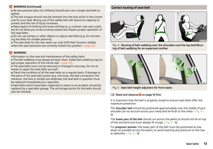 15
15 16
16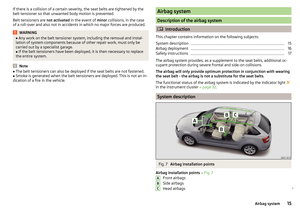 17
17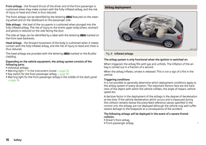 18
18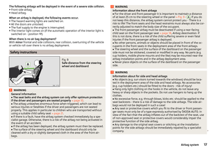 19
19 20
20 21
21 22
22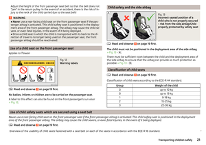 23
23 24
24 25
25 26
26 27
27 28
28 29
29 30
30 31
31 32
32 33
33 34
34 35
35 36
36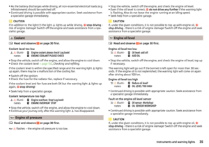 37
37 38
38 39
39 40
40 41
41 42
42 43
43 44
44 45
45 46
46 47
47 48
48 49
49 50
50 51
51 52
52 53
53 54
54 55
55 56
56 57
57 58
58 59
59 60
60 61
61 62
62 63
63 64
64 65
65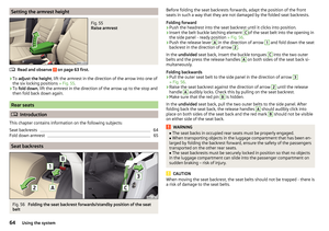 66
66 67
67 68
68 69
69 70
70 71
71 72
72 73
73 74
74 75
75 76
76 77
77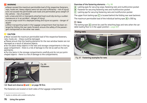 78
78 79
79 80
80 81
81 82
82 83
83 84
84 85
85 86
86 87
87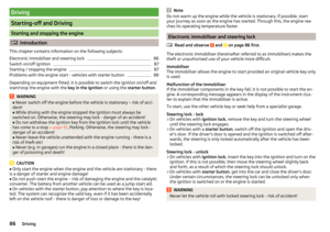 88
88 89
89 90
90 91
91 92
92 93
93 94
94 95
95 96
96 97
97 98
98 99
99 100
100 101
101 102
102 103
103 104
104 105
105 106
106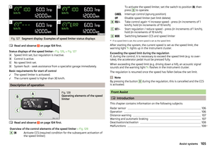 107
107 108
108 109
109 110
110 111
111 112
112 113
113 114
114 115
115 116
116 117
117 118
118 119
119 120
120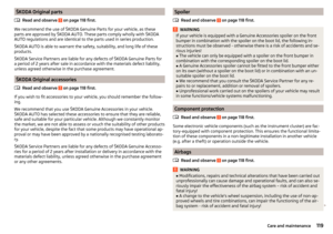 121
121 122
122 123
123 124
124 125
125 126
126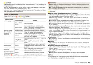 127
127 128
128 129
129 130
130 131
131 132
132 133
133 134
134 135
135 136
136 137
137 138
138 139
139 140
140 141
141 142
142 143
143 144
144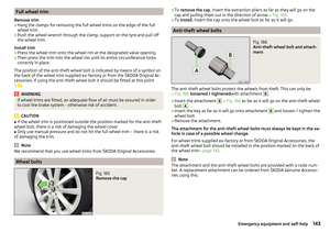 145
145 146
146 147
147 148
148 149
149 150
150 151
151 152
152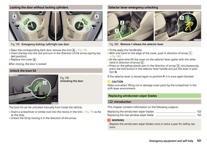 153
153 154
154 155
155 156
156 157
157 158
158 159
159 160
160 161
161 162
162 163
163 164
164 165
165 166
166 167
167 168
168 169
169 170
170 171
171 172
172 173
173 174
174 175
175 176
176 177
177 178
178 179
179 180
180 181
181 182
182 183
183