Page 3233 of 3641
ST-12
< REMOVAL AND INSTALLATION >
STEERING SHAFT
STEERING SHAFT
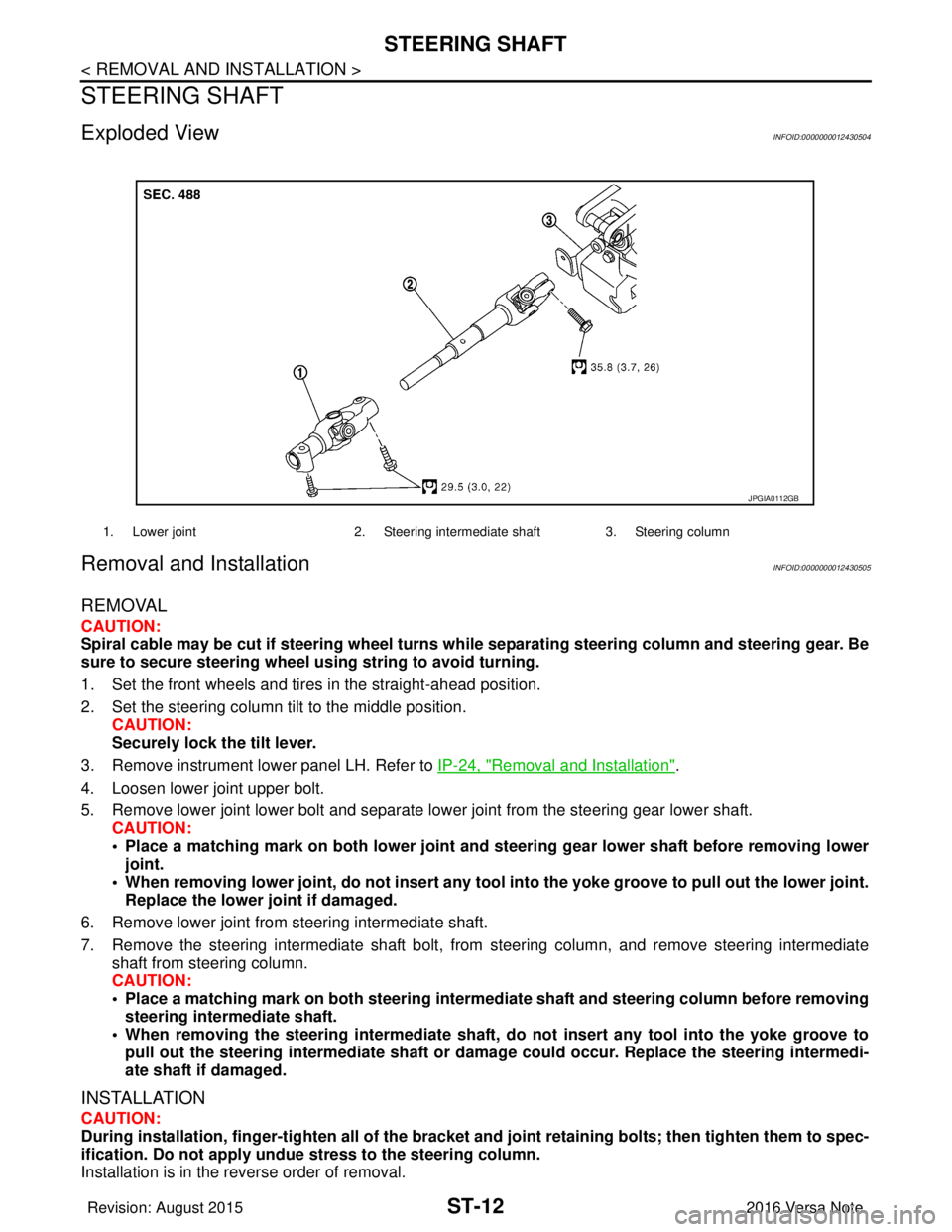
Exploded ViewINFOID:0000000012430504
Removal and InstallationINFOID:0000000012430505
REMOVAL
CAUTION:
Spiral cable may be cut if steering wheel turns while separating steering column and steering gear. Be
sure to secure steering wheel us ing string to avoid turning.
1. Set the front wheels and tires in the straight-ahead position.
2. Set the steering column tilt to the middle position. CAUTION:
Securely lock the tilt lever.
3. Remove instrument lower panel LH. Refer to IP-24, "
Removal and Installation".
4. Loosen lower joint upper bolt.
5. Remove lower joint lower bolt and separate lower joint from the steering gear lower shaft. CAUTION:
• Place a matching mark on both lower joint and st eering gear lower shaft before removing lower
joint.
• When removing lower joint, do not insert any tool into the yoke groove to pull out the lower joint.
Replace the lower joint if damaged.
6. Remove lower joint from steering intermediate shaft.
7. Remove the steering intermediate shaft bolt, from steering column, and remove steering intermediate
shaft from steering column.
CAUTION:
• Place a matching mark on both steering interme diate shaft and steering column before removing
steering intermediate shaft.
• When removing the steering intermediate shaft, do not insert any tool into the yoke groove to pull out the steering intermediate shaft or dama ge could occur. Replace the steering intermedi-
ate shaft if damaged.
INSTALLATION
CAUTION:
During installation, finger-tighten all of the bracket and joint retainin g bolts; then tighten them to spec-
ification. Do not ap ply undue stress to the steering column.
Installation is in the reverse order of removal.
1. Lower joint 2. Steering intermediate shaft 3. Steering column
JPGIA0112GB
Revision: August 2015 2016 Versa Note
cardiagn.com
Page 3475 of 3641
![NISSAN NOTE 2016 Service Repair Manual TM-234
< REMOVAL AND INSTALLATION >[CVT: RE0F11A]
CONTROL CABLE
CONTROL CABLE
Exploded ViewINFOID:0000000012431179
Removal and InstallationINFOID:0000000012431180
CAUTION:
Always apply the parking bra NISSAN NOTE 2016 Service Repair Manual TM-234
< REMOVAL AND INSTALLATION >[CVT: RE0F11A]
CONTROL CABLE
CONTROL CABLE
Exploded ViewINFOID:0000000012431179
Removal and InstallationINFOID:0000000012431180
CAUTION:
Always apply the parking bra](/manual-img/5/57363/w960_57363-3474.png)
TM-234
< REMOVAL AND INSTALLATION >[CVT: RE0F11A]
CONTROL CABLE
CONTROL CABLE
Exploded ViewINFOID:0000000012431179
Removal and InstallationINFOID:0000000012431180
CAUTION:
Always apply the parking brake before performing removal
and installation.
REMOVAL
1. Remove the battery negative terminal. Refer to PG-70, "Exploded View".
2. Remove the TCM and bracket. Refer to TM-239, "
Removal and Installation".
3. Remove the IPDM E/R. Refer to PCS-30, "
Removal and Installation".
4. Remove the battery tray and bracket.
5. Remove instrument lower panel LH. Refer to IP-24, "
Removal and Installation".
6. Remove the center console assembly. Refer to IP-18, "
Removal and Installation".
7. Remove the control cable from the shift selector assembly.
8. Disengage the pawls (B) of the grommet (A), and pull downward to remove.
9. Remove the control cable nut from the manual lever.
1. Bracket B 2. Lock plate3. Transaxle assembly
4. Bracket A 5. Control cable6. Shift selector assembly
A: Manual lever B: Grommet
JSDIA1921GB
JSDIA1809ZZ
Revision: August 2015 2016 Versa Note
cardiagn.com
Page 3478 of 3641
![NISSAN NOTE 2016 Service Repair Manual KEY INTERLOCK CABLETM-237
< REMOVAL AND INSTALLATION > [CVT: RE0F11A]
C
EF
G H
I
J
K L
M A
B
TM
N
O P
KEY INTERLOCK CABLE
Exploded ViewINFOID:0000000012431182
Removal and InstallationINFOID:0000000012 NISSAN NOTE 2016 Service Repair Manual KEY INTERLOCK CABLETM-237
< REMOVAL AND INSTALLATION > [CVT: RE0F11A]
C
EF
G H
I
J
K L
M A
B
TM
N
O P
KEY INTERLOCK CABLE
Exploded ViewINFOID:0000000012431182
Removal and InstallationINFOID:0000000012](/manual-img/5/57363/w960_57363-3477.png)
KEY INTERLOCK CABLETM-237
< REMOVAL AND INSTALLATION > [CVT: RE0F11A]
C
EF
G H
I
J
K L
M A
B
TM
N
O P
KEY INTERLOCK CABLE
Exploded ViewINFOID:0000000012431182
Removal and InstallationINFOID:0000000012431183
REMOVAL
CAUTION:
Always apply the parking brake before pe rforming removal and installation.
1. Move the shift selector to the “N” position.
2. Remove the shift selector handle. Refer to TM-232, "
Disassembly and Assembly".
3. Remove the instrumental lower panel LH. Refer to IP-24, "
Removal and Installation".
4. Remove steering column covers. Refer to IP-17, "
Removal and Installation".
5. Remove the center console. Refer to IP-18, "
Removal and Installation".
6. Move the shift selector to the “P” position.
7. Press the pawls (B) of the key interlock cable slider (A) while sliding it in the direction of the casing cap (C), and separate the
adjusting holder (D) and slider.
8. Remove the key interlock cable from the shift selector assembly.
1. Shift selector assembly 2. Key interlock cable A: Steering lock unit
B: Lock plate C: Clip
ALDIA0262ZZ
(E) :Key interlock rod
JSDIA1797ZZ
Revision: August 2015 2016 Versa Note
cardiagn.com
Page 3511 of 3641
DUCT AND GRILLEVTL-5
< REMOVAL AND INSTALLATION >
C
DE
F
G H
J
K L
M A
B
VTL
N
O P
REMOVAL AND INSTALLATION
DUCT AND GRILLE
Exploded ViewINFOID:0000000012430549
FRONT
AWIIA1860ZZ
1. Center defroster duct 2. Side defroster duct (LH)3. Center ventilator duct
4. Side ventilator grille (LH) 5. Side defroster grille (LH)6. Heating and cooling unit assembly
7. Foot duct (LH) 8. Foot duct (RH)9. Center ventilator grille (LH)
10. Cluster lid C 11. Center ventilator grille (RH) 12. Side defroster grille (RH)
13. Instrument panel assembly 14. Side ventilator grille (RH) 15. Side defroster duct (RH)
Revision: August 2015 2016 Versa Note
cardiagn.com
Page 3512 of 3641
VTL-6
< REMOVAL AND INSTALLATION >
DUCT AND GRILLE
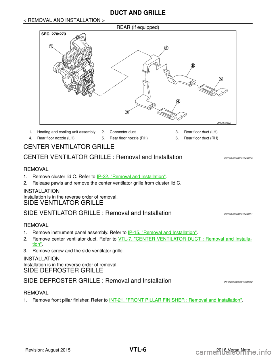
REAR (if equipped)
CENTER VENTILAT O R G R I L L E
CENTER VENTILATOR GRILLE : Removal and InstallationINFOID:0000000012430550
REMOVAL
1. Remove cluster lid C. Refer to IP-22, "Removal and Installation".
2. Release pawls and remove the center ventilator grille from cluster lid C.
INSTALLATION
Installation is in the reverse order of removal.
SIDE VENTILATOR GRILLE
SIDE VENTILATOR GRILLE : Removal and InstallationINFOID:0000000012430551
REMOVAL
1. Remove instrument panel assembly. Refer to IP-15, "Removal and Installation".
2. Remove center ventilator duct. Refer to VTL-7, "
CENTER VENTILATOR DUCT : Removal and Installa-
tion".
3. Remove screw and the side ventilator grille.
INSTALLATION
Installation is in the reverse order of removal.
SIDE DEFROSTER GRILLE
SIDE DEFROSTER GRILLE : Removal and InstallationINFOID:0000000012430552
REMOVAL
1. Remove front pillar finisher. Refer to INT-21, "FRONT PILLAR FINISHER : Removal and Installation".
JMIIA1736ZZ
1. Heating and cooling unit assembly 2. Connector duct 3. Rear floor duct (LH)
4. Rear floor nozzle (LH) 5. Rear floor nozzle (RH) 6. Rear floor duct (RH)
Revision: August 2015 2016 Versa Note
cardiagn.com
Page 3513 of 3641
DUCT AND GRILLEVTL-7
< REMOVAL AND INSTALLATION >
C
DE
F
G H
J
K L
M A
B
VTL
N
O P
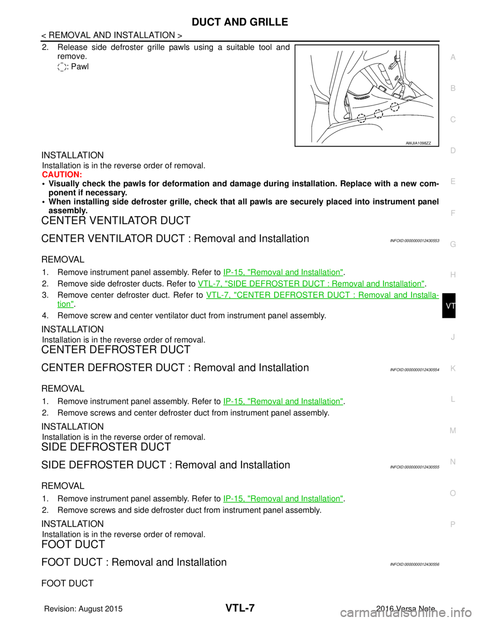
2. Release side defroster grille pawls using a suitable tool and remove.
: Pawl
INSTALLATION
Installation is in the reverse order of removal.
CAUTION:
• Visually check the pawls for deformation and dama ge during installation. Replace with a new com-
ponent if necessary.
• When installing side defroster grille, check that all pawls are securely placed into instrument panel assembly.
CENTER VENTILATOR DUCT
CENTER VENTILATOR DUCT : Removal and InstallationINFOID:0000000012430553
REMOVAL
1. Remove instrument panel assembly. Refer to IP-15, "Removal and Installation".
2. Remove side defroster ducts. Refer to VTL-7, "
SIDE DEFROSTER DUCT : Removal and Installation".
3. Remove center defroster duct. Refer to VTL-7, "
CENTER DEFROSTER DUCT : Removal and Installa-
tion".
4. Remove screw and center ventilator duct from instrument panel assembly.
INSTALLATION
Installation is in the reverse order of removal.
CENTER DEFROSTER DUCT
CENTER DEFROSTER DUCT : Removal and InstallationINFOID:0000000012430554
REMOVAL
1. Remove instrument panel assembly. Refer to IP-15, "Removal and Installation".
2. Remove screws and center defroster duct from instrument panel assembly.
INSTALLATION
Installation is in the reverse order of removal.
SIDE DEFROSTER DUCT
SIDE DEFROSTER DUCT : Removal and InstallationINFOID:0000000012430555
REMOVAL
1. Remove instrument panel assembly. Refer to IP-15, "Removal and Installation".
2. Remove screws and side defroster duct from instrument panel assembly.
INSTALLATION
Installation is in the reverse order of removal.
FOOT DUCT
FOOT DUCT : Removal and InstallationINFOID:0000000012430556
FOOT DUCT
AWJIA1098ZZ
Revision: August 2015 2016 Versa Note
cardiagn.com
Page 3514 of 3641
VTL-8
< REMOVAL AND INSTALLATION >
DUCT AND GRILLE
Removal
1. Remove instrument panel assembly. Refer to IP-15, "Removal and Installation".
2. Remove screws and foot duct (LH/RH) from heating and cooling unit assembly.
Installation
Installation is in the reverse order of removal.
REAR FLOOR DUCT
REAR FLOOR DUCT : Remo val and InstallationINFOID:0000000012430557
REMOVAL
1. Remove driver seat (if necessary). Refer to SE-20, "DRIVER SIDE : Removal and Installation".
2. Remove passenger seat (if necessary). Refer to SE-22, "
PASSENGER SIDE : Removal and Installation".
3. Remove rear seat cushion. Refer to SE-26, "
SEAT CUSHION : Removal and Installation".
4. Remove dash side finisher (LH/RH). Refer to INT-24, "
DASH SIDE FINISHER : Removal and Installation".
5. Remove center pillar lower finisher (LH/RH). Refer to INT-25, "
CENTER PILLAR LOWER FINISHER :
Removal and Installation".
6. Remove center console lower. Refer to IP-20, "
Removal and Installation"
7. Position floor trim and floor insulators aside.
8. Release and remove rear floor ducts.
INSTALLATION
Install in the reverse order of removal.
Revision: August 2015 2016 Versa Note
cardiagn.com
Page 3515 of 3641
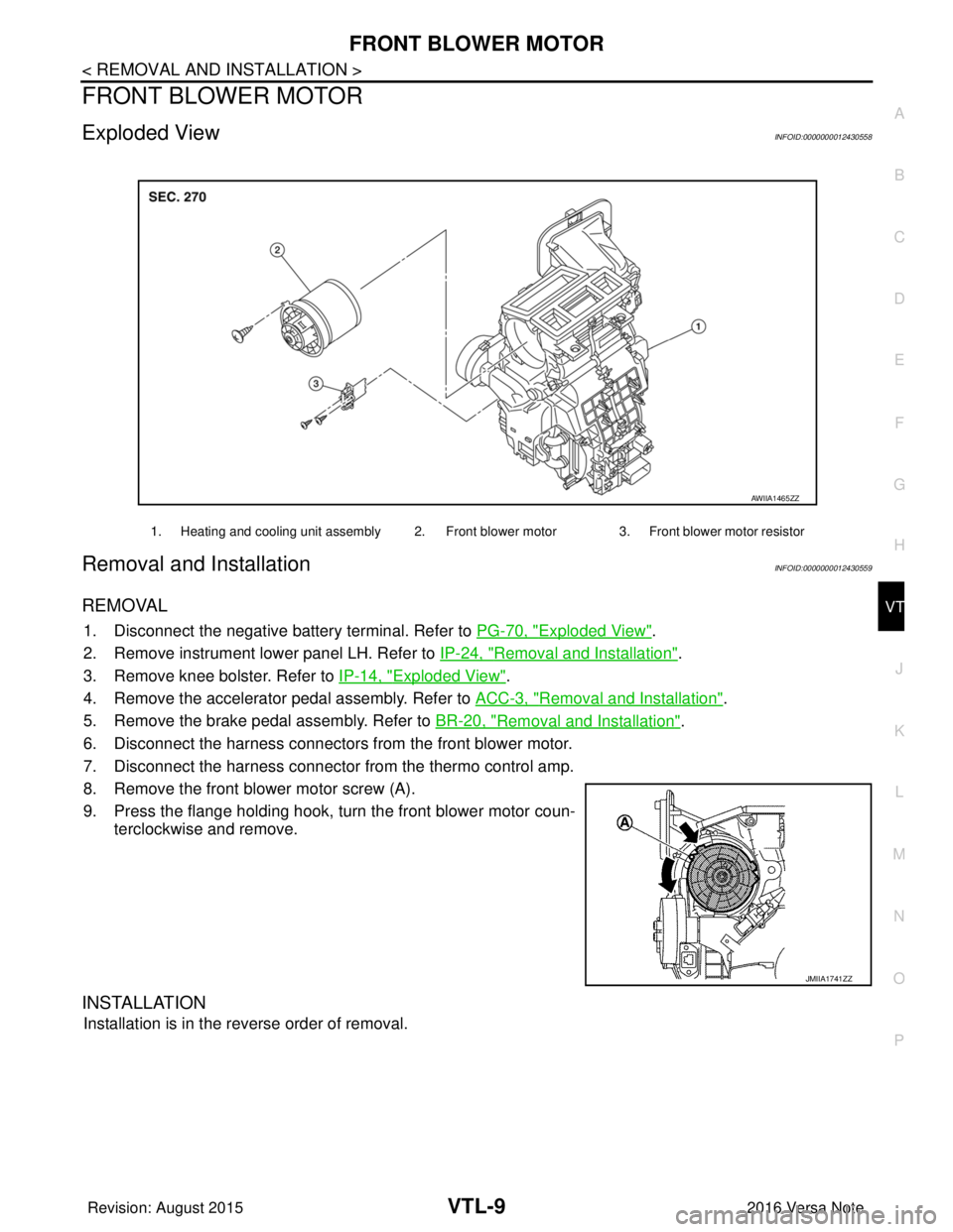
FRONT BLOWER MOTORVTL-9
< REMOVAL AND INSTALLATION >
C
DE
F
G H
J
K L
M A
B
VTL
N
O P
FRONT BLOWER MOTOR
Exploded ViewINFOID:0000000012430558
Removal and InstallationINFOID:0000000012430559
REMOVAL
1. Disconnect the negative battery terminal. Refer to PG-70, "Exploded View".
2. Remove instrument lower panel LH. Refer to IP-24, "
Removal and Installation".
3. Remove knee bolster. Refer to IP-14, "
Exploded View".
4. Remove the accelerator pedal assembly. Refer to ACC-3, "
Removal and Installation".
5. Remove the brake pedal assembly. Refer to BR-20, "
Removal and Installation".
6. Disconnect the harness connectors from the front blower motor.
7. Disconnect the harness connector from the thermo control amp.
8. Remove the front blower motor screw (A).
9. Press the flange holding hook, turn the front blower motor coun- terclockwise and remove.
INSTALLATION
Installation is in the reverse order of removal.
1. Heating and cooling unit assembly 2. Front blower motor 3. Front blower motor resistor
AWIIA1465ZZ
JMIIA1741ZZ
Revision: August 2015 2016 Versa Note
cardiagn.com