2016 NISSAN NOTE key
[x] Cancel search: keyPage 1672 of 3641

EXL-20
< SYSTEM DESCRIPTION >
DIAGNOSIS SYSTEM (IPDM E/R)
DIAGNOSIS SYSTEM (IPDM E/R)
Diagnosis DescriptionINFOID:0000000012542316
AUTO ACTIVE TEST
Description
In auto active test, the IPDM E/R sends a drive signal to the following systems to check their operation:
• Front wiper (LO, HI)
• Parking lamp
• Side marker lamp
• License plate lamp
• Tail lamp
• Front fog lamp
• Headlamp (LO, HI)
• A/C compressor (magnet clutch)
• Cooling fan
Operation Procedure
NOTE:
Never perform auto active test in the following conditions:
• Passenger door is open
• CONSULT is connected
1. Close the hood and lift the wiper arms from the windshield. (Prevent windshield damage due to wiper
operation)
NOTE:
When auto active test is performed with hood opened, sprinkle water on windshield beforehand.
2. Turn the ignition switch OFF.
3. Turn the ignition switch ON, and within 20 seconds, pr ess the driver door switch 10 times. Then turn the
ignition switch OFF.
4. Turn the ignition switch ON within 10 seconds. Af ter that the horn sounds once and the auto active test
starts.
5. After a series of the following operations is repeated 3 times, auto active test is completed.
NOTE:
• When auto active test has to be cancelled halfw ay through test, turn the ignition switch OFF.
• When auto active test is not activated, door swit ch may be the cause. Check door switch. Refer to DLK-98,
"ComponentFunctionCheck" (with Intelligent Key system) or DLK-232, "ComponentFunctionCheck"
(without Intelligent Key system).
Inspection in Auto Active Test
When auto active test is actuated, the following operation sequence is repeated 3 times.
Operation se-
quence Inspection location
Operation
1 Front wiper LO for 5 seconds → HI for 5 seconds
2 •Parking lamp
• Side marker lamp
• License plate lamp
• Tail lamp
• Front fog lamp (if equipped) 10 seconds
3 Headlamp LO for 10 seconds →HI ON ⇔ OFF 5 times
4 A/C compressor (magnet clutch) ON ⇔ OFF 5 times
5 Cooling fan LO for 5 seconds → MID for 3 seconds → HI for 2 seconds
Revision: August 2015 2016 Versa Note
cardiagn.com
Page 1676 of 3641
EXL-24
< ECU DIAGNOSIS INFORMATION >
BCM, IPDM E/R
ECU DIAGNOSIS INFORMATION
BCM, IPDM E/R
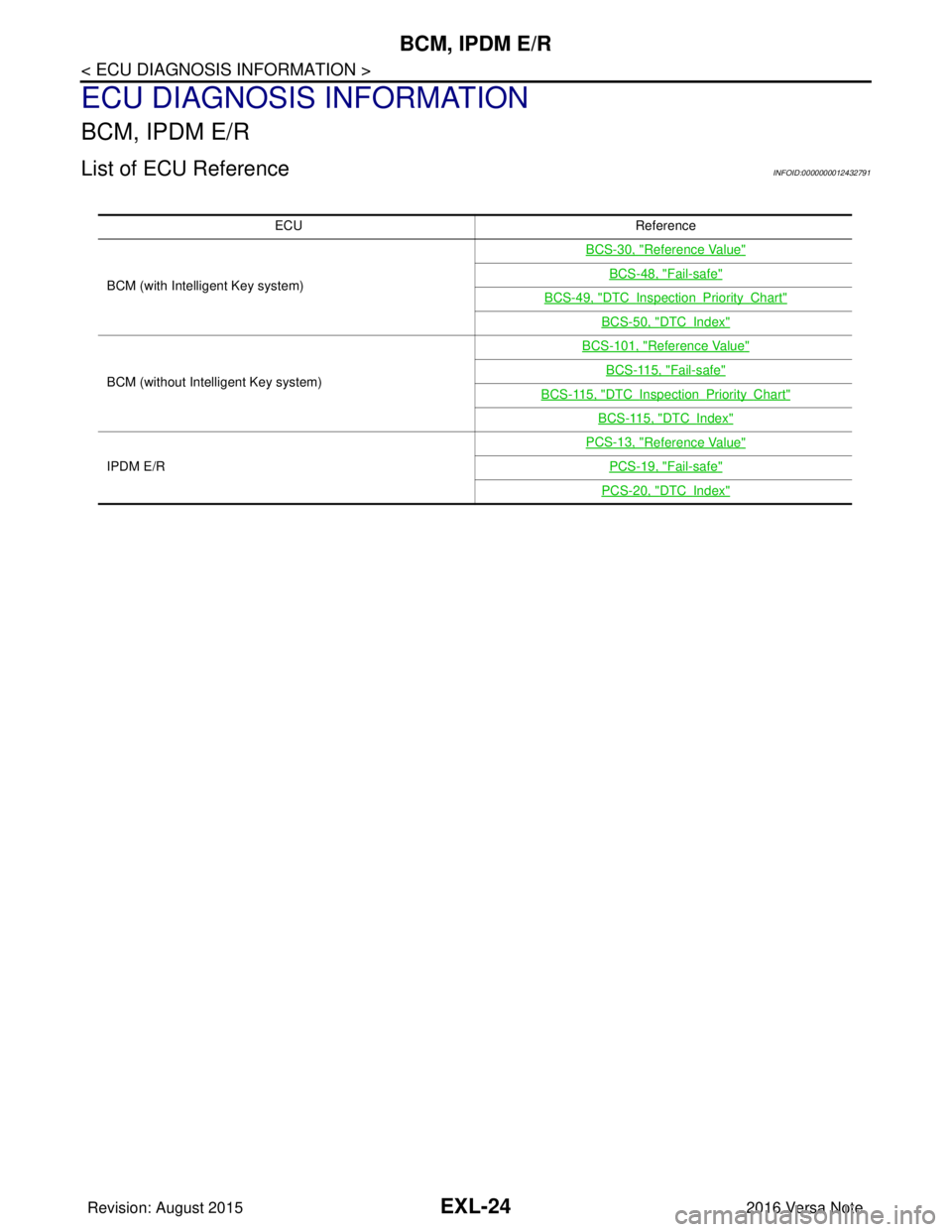
List of ECU ReferenceINFOID:0000000012432791
ECUReference
BCM (with Intelligent Key system) BCS-30, "
Reference Value"
BCS-48, "Fail-safe"
BCS-49, "DTCInspectionPriorityChart"
BCS-50, "DTCIndex"
BCM (without Intelligent Key system)BCS-101, "
Reference Value"
BCS-115, "Fail-safe"
BCS-115, "DTCInspectionPriorityChart"
BCS-115, "DTCIndex"
IPDM E/R
PCS-13, "
Reference Value"
PCS-19, "Fail-safe"
PCS-20, "DTCIndex"
Revision: August 2015
2016 Versa Note
cardiagn.com
Page 1726 of 3641

EXL-74
< DTC/CIRCUIT DIAGNOSIS >
POWER SUPPLY AND GROUND CIRCUIT
DTC/CIRCUIT DIAGNOSIS
POWER SUPPLY AND GROUND CIRCUIT
BCM (BODY CONTROL SYSTEM) (WITH INTELLIGENT KEY SYSTEM)
BCM (BODY CONTROL SYSTEM) (WITH INTELLIGENT KEY SYSTEM) : Diagnosis
Procedure
INFOID:0000000012542318
Regarding Wiring Diagram information, refer to BCS-52, "Wiring Diagram".
1.CHECK FUSES AND FUSIBLE LINK
Check that the following fuses and fusible link are not blown.
Is the fuse blown?
YES >> Replace the blown fuse or fusible link after repairing the affected circuit.
NO >> GO TO 2.
2.CHECK POWER SUPPLY CIRCUIT
1. Disconnect BCM connector M99.
2. Check voltage between BCM connector M99 and ground.
Is the inspection result normal?
YES >> GO TO 3.
NO >> Repair harness or connector.
3.CHECK GROUND CIRCUIT
Check continuity between BCM connector M99 and ground.
Is the inspection result normal?
YES >> Inspection End.
NO >> Repair harness or connector.
BCM (BODY CONTROL SYSTEM) (WIT HOUT INTELLIGENT KEY SYSTEM)
BCM (BODY CONTROL SYSTEM) (WITHOUT INTELLIGENT KEY SYSTEM) : Diag-
nosis Procedure
INFOID:0000000012542319
Regarding Wiring Diagram information, refer to BCS-117, "Wiring Diagram".
Terminal No.Signal nameFuses and fusible link No.
57 Battery power supply 12 (10A)
70 G (40A)
BCM
Ground Voltage
Connector Terminal
M99 57
— Battery voltage
70
BCM GroundContinuity
Connector Terminal
M99 67—Yes
Revision: August 2015 2016 Versa Note
cardiagn.com
Page 1738 of 3641
EXL-86
< DTC/CIRCUIT DIAGNOSIS >
TURN SIGNAL LAMP CIRCUIT
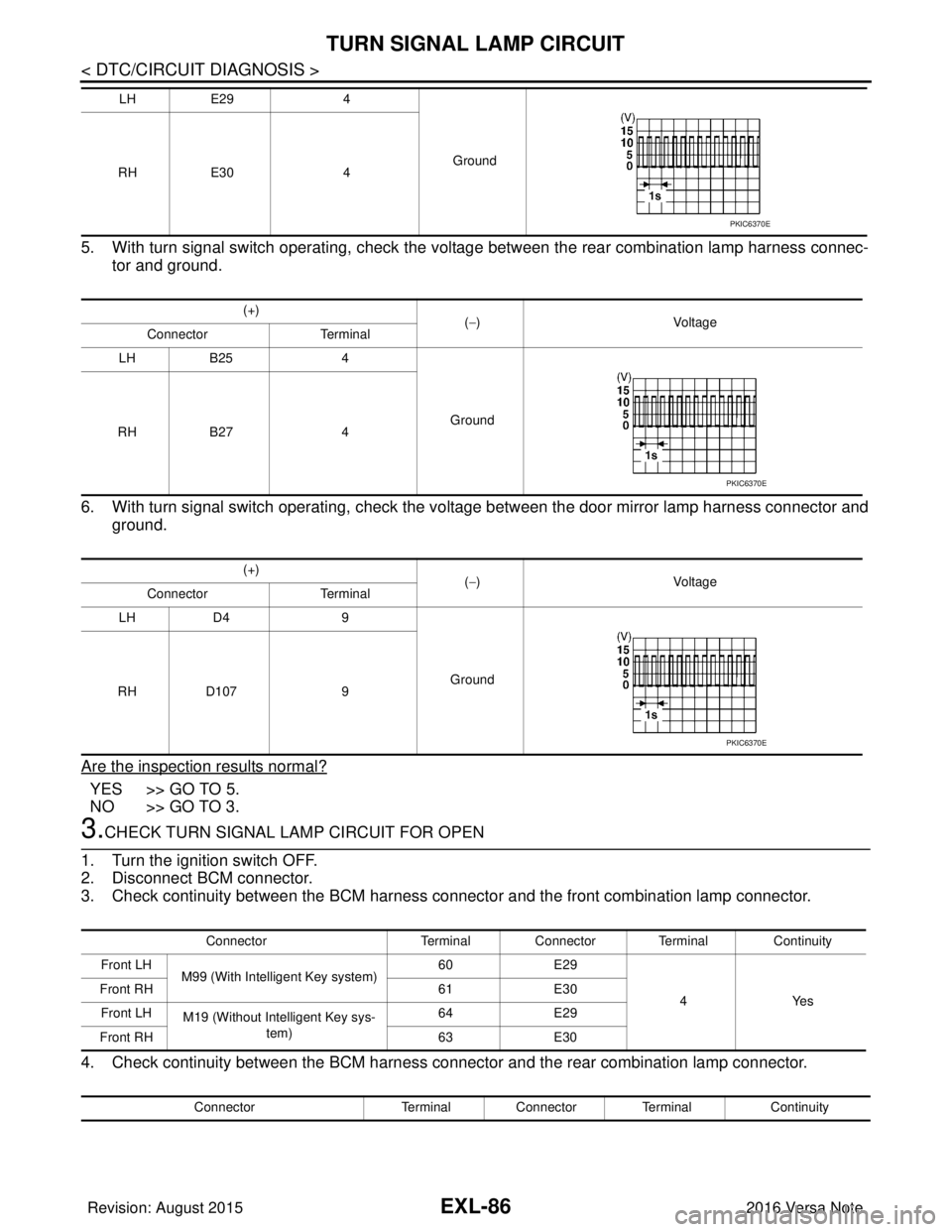
5. With turn signal switch operating, check the voltage between the rear combination lamp harness connec-tor and ground.
6. With turn signal switch operating, check the vo ltage between the door mirror lamp harness connector and
ground.
Are the inspection results normal?
YES >> GO TO 5.
NO >> GO TO 3.
3.CHECK TURN SIGNAL LAMP CIRCUIT FOR OPEN
1. Turn the ignition switch OFF.
2. Disconnect BCM connector.
3. Check continuity between the BCM harness connector and the front combination lamp connector.
4. Check continuity between the BCM harness connector and the rear combination lamp connector.
LH E29 4
Ground
RH E30 4
(+) (−) Voltage
Connector Terminal
LH B25 4
Ground
RH B27 4
(+) (−) Voltage
Connector Terminal
LH D4 9
Ground
RH D107 9
PKIC6370E
PKIC6370E
PKIC6370E
Connector Terminal Connector Terminal Continuity
Front LH M99 (With Intelligent Key system) 60
E29
4Yes
Front RH
61E30
Front LH M19 (Without Intelligent Key sys-
tem) 64
E29
Front RH 63E30
Connector Terminal Connector Terminal Continuity
Revision: August 2015 2016 Versa Note
cardiagn.com
Page 1739 of 3641
TURN SIGNAL LAMP CIRCUITEXL-87
< DTC/CIRCUIT DIAGNOSIS >
C
DE
F
G H
I
J
K
M A
B
EXL
N
O P
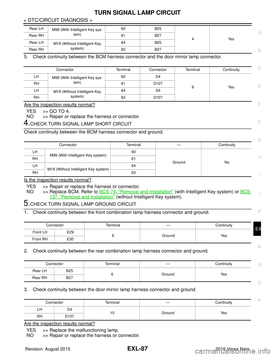
5. Check continuity between the BCM harness connector and the door mirror lamp connector.
Are the inspection results normal?
YES >> GO TO 4.
NO >> Repair or replace the harness or connector.
4.CHECK TURN SIGNAL LAMP SHORT CIRCUIT
Check continuity between the BCM harness connector and ground.
Is the inspection results normal?
YES >> Repair or replace the harness or connector.
NO >> Replace BCM. Refer to BCS-74, "
Removal and Installation" (with Intelligent Key system) or BCS-
137, "Removal and Installation" (without Intelligent Key system).
5.CHECK TURN SIGNAL LAMP GROUND CIRCUIT
1. Check continuity between the front combination lamp harness connector and ground.
2. Check continuity between the rear combination lamp harness connector and ground.
3. Check continuity between the door mirror lamp harness connector and ground.
Are the inspection results normal?
YES >> Replace the malfunctioning lamp.
NO >> Repair or replace the harness or connector.
Rear LH M99 (With Intelligent Key sys-
tem) 60
B25
4Y es
Rear RH
61B27
Rear LH M19 (Without Intelligent Key
system) 64
B25
Rear RH 63B27
Connector Terminal Connector Terminal Continuity
LH M99 (With Intelligent Key sys-
tem) 60
D4
9Y es
RH
61D107
LH M19 (Without Intelligent Key
system) 64
D4
RH 63D107
Connector Terminal—Continuity
LH M99 (With Intelligent Key system) 60
Ground No
RH
61
LH M19 (Without Intelligent Key system) 64
RH 63
ConnectorTerminal —Continuity
Front LH E29
6 Ground Yes
Front RH E30
Connector Terminal —Continuity
Rear LH B25
6 Ground Yes
Rear RH B27
Connector Terminal —Continuity
LH D4
10 Ground Yes
RH D107
Revision: August 2015 2016 Versa Note
cardiagn.com
Page 1743 of 3641
EXTERIOR LIGHTING SYSTEM SYMPTOMSEXL-91
< SYMPTOM DIAGNOSIS >
C
DE
F
G H
I
J
K
M A
B
EXL
N
O P
SYMPTOM DIAGNOSIS
EXTERIOR LIGHTING SYSTEM SYMPTOMS
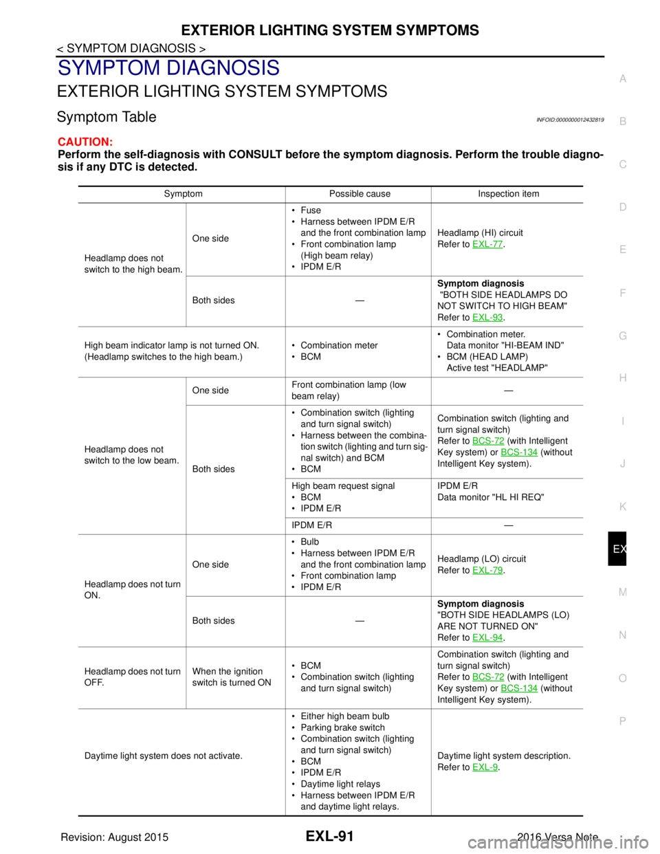
Symptom TableINFOID:0000000012432819
CAUTION:
Perform the self-diagnosis with CONSULT before th e symptom diagnosis. Perform the trouble diagno-
sis if any DTC is detected.
Symptom Possible causeInspection item
Headlamp does not
switch to the high beam. One side
•Fuse
• Harness between IPDM E/R
and the front combination lamp
• Front combination lamp
(High beam relay)
• IPDM E/R Headlamp (HI) circuit
Refer to EXL-77
.
Both sides — Symptom diagnosis
"BOTH SIDE HEADLAMPS DO
NOT SWITCH TO HIGH BEAM"
Refer to EXL-93
.
High beam indicator lamp is not turned ON.
(Headlamp switches to the high beam.) • Combination meter
•BCM• Combination meter.
Data monitor "HI-BEAM IND"
• BCM (HEAD LAMP)
Active test "HEADLAMP"
Headlamp does not
switch to the low beam. One side
Front combination lamp (low
beam relay) —
Both sides • Combination switch (lighting
and turn signal switch)
• Harness between the combina- tion switch (lighting and turn sig-
nal switch) and BCM
•BCM Combination switch (lighting and
turn signal switch)
Refer to BCS-72
(with Intelligent
Key system) or BCS-134
(without
Intelligent Key system).
High beam request signal
•BCM
• IPDM E/R IPDM E/R
Data monitor "HL HI REQ"
IPDM E/R —
Headlamp does not turn
ON. One side
•Bulb
• Harness between IPDM E/R
and the front combination lamp
• Front combination lamp
• IPDM E/R Headlamp (LO) circuit
Refer to EXL-79
.
Both sides — Symptom diagnosis
"BOTH SIDE HEADLAMPS (LO)
ARE NOT TURNED ON"
Refer to EXL-94
.
Headlamp does not turn
OFF. When the ignition
switch is turned ON•BCM
• Combination switch (lighting
and turn signal switch) Combination switch (lighting and
turn signal switch)
Refer to BCS-72
(with Intelligent
Key system) or BCS-134
(without
Intelligent Key system).
Daytime light system does not activate. • Either high beam bulb
• Parking brake switch
• Combination switch (lighting
and turn signal switch)
•BCM
• IPDM E/R
• Daytime light relays
• Harness between IPDM E/R
and daytime light relays. Daytime light system description.
Refer to EXL-9
.
Revision: August 2015
2016 Versa Note
cardiagn.com
Page 1745 of 3641
BOTH SIDE HEADLAMPS DO NOT SWITCH TO HIGH BEAM
EXL-93
< SYMPTOM DIAGNOSIS >
C
D E
F
G H
I
J
K
M A
B
EXL
N
O P
BOTH SIDE HEADLAMPS DO NOT SWITCH TO HIGH BEAM
DescriptionINFOID:0000000012432820
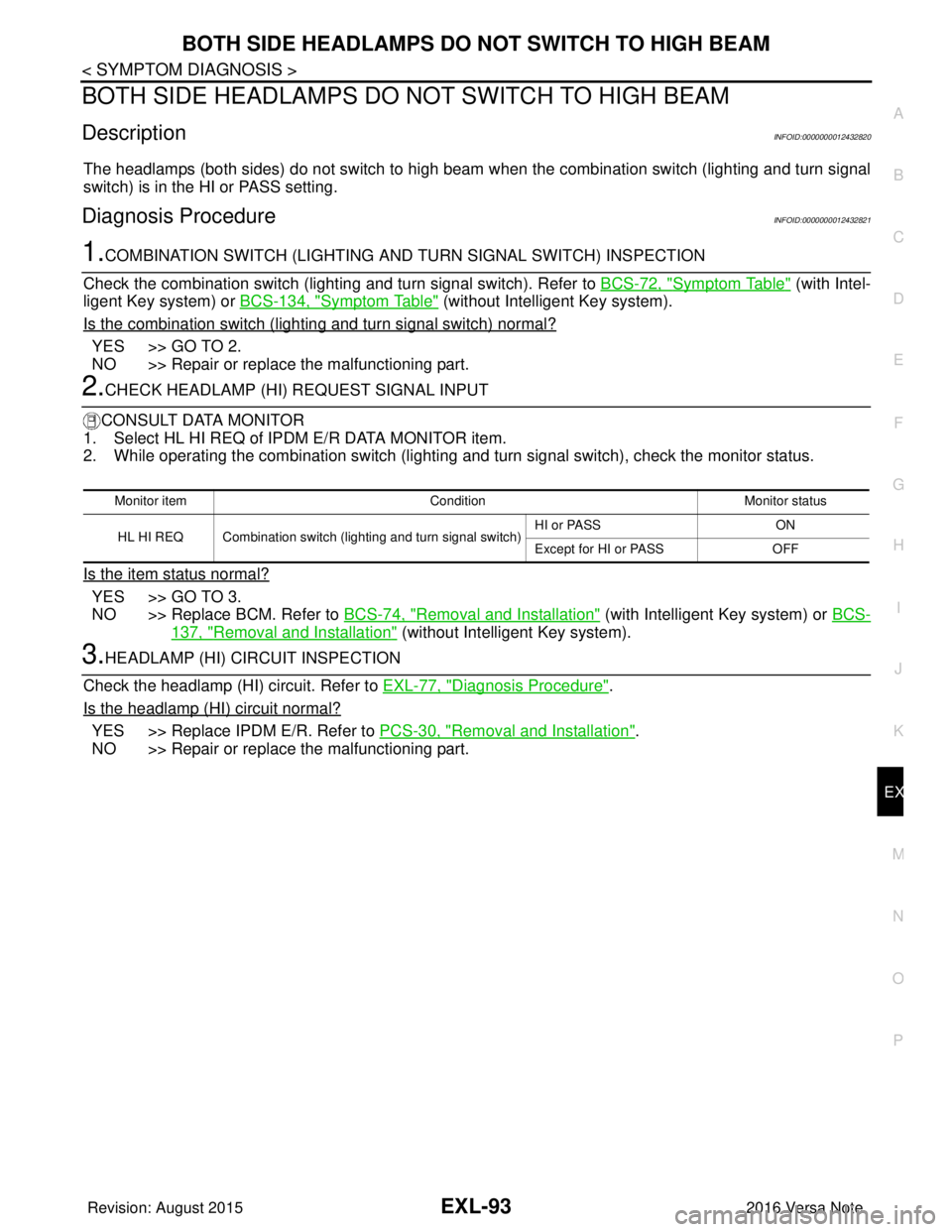
The headlamps (both sides) do not switch to high beam when the combination switch (lighting and turn signal
switch) is in the HI or PASS setting.
Diagnosis ProcedureINFOID:0000000012432821
1.COMBINATION SWITCH (LIGHTING AND TURN SIGNAL SWITCH) INSPECTION
Check the combination switch (lighti ng and turn signal switch). Refer to BCS-72, "
Symptom Table" (with Intel-
ligent Key system) or BCS-134, "
Symptom Table" (without Intelligent Key system).
Is the combination switch (lighting and turn signal switch) normal?
YES >> GO TO 2.
NO >> Repair or replace the malfunctioning part.
2.CHECK HEADLAMP (HI) REQUEST SIGNAL INPUT
CONSULT DATA MONITOR
1. Select HL HI REQ of IP DM E/R DATA MONITOR item.
2. While operating the combination switch (lighting and turn signal switch), check the monitor status.
Is the item status normal?
YES >> GO TO 3.
NO >> Replace BCM. Refer to BCS-74, "
Removal and Installation" (with Intelligent Key system) or BCS-
137, "Removal and Installation" (without Intelligent Key system).
3.HEADLAMP (HI) CIRCUIT INSPECTION
Check the headlamp (HI) circuit. Refer to EXL-77, "
Diagnosis Procedure".
Is the headlamp (HI) circuit normal?
YES >> Replace IPDM E/R. Refer to PCS-30, "Removal and Installation".
NO >> Repair or replace the malfunctioning part.
Monitor item ConditionMonitor status
HL HI REQ Combination switch (lighting and turn signal switch) HI or PASS
ON
Except for HI or PASS OFF
Revision: August 2015 2016 Versa Note
cardiagn.com
Page 1746 of 3641
EXL-94
< SYMPTOM DIAGNOSIS >
BOTH SIDE HEADLAMPS (LO) ARE NOT TURNED ON
BOTH SIDE HEADLAMPS (LO) ARE NOT TURNED ON
DescriptionINFOID:0000000012432822
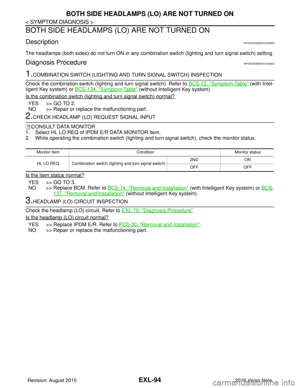
The headlamps (both sides) do not turn ON in any combination switch (lighting and turn signal switch) setting.
Diagnosis ProcedureINFOID:0000000012432823
1.COMBINATION SWITCH (LIGHTING AND TURN SIGNAL SWITCH) INSPECTION
Check the combination switch (lighting and turn signal switch). Refer to BCS-72, "
Symptom Table" (with Intel-
ligent Key system) or BCS-134, "
Symptom Table" (without Intelligent Key system).
Is the combination switch (lighting and turn signal switch) normal?
YES >> GO TO 2.
NO >> Repair or replace the malfunctioning part.
2.CHECK HEADLAMP (LO) REQUEST SIGNAL INPUT
CONSULT DATA MONITOR
1. Select HL LO REQ of IPDM E/R DATA MONITOR item.
2. While operating the combination switch (lighting and turn signal switch), check the monitor status.
Is the item status normal?
YES >> GO TO 3.
NO >> Replace BCM. Refer to BCS-74, "
Removal and Installation" (with Intelligent Key system) or BCS-
137, "Removal and Installation" (without Intelligent Key system).
3.HEADLAMP (LO) CIRCUIT INSPECTION
Check the headlamp (LO) circuit. Refer to EXL-79, "
Diagnosis Procedure".
Is the headlamp (LO) circuit normal?
YES >> Replace IPDM E/R. Refer to PCS-30, "Removal and Installation".
NO >> Repair or replace the malfunctioning part.
Monitor item ConditionMonitor status
HL LO REQ Combination switch (lighting and turn signal switch) 2ND
ON
OFF OFF
Revision: August 2015 2016 Versa Note
cardiagn.com