2016 NISSAN NOTE key
[x] Cancel search: keyPage 1747 of 3641
PARKING, LICENSE PLATE AND TAIL LAMPS ARE NOT TURNED ON
EXL-95
< SYMPTOM DIAGNOSIS >
C
D E
F
G H
I
J
K
M A
B
EXL
N
O P
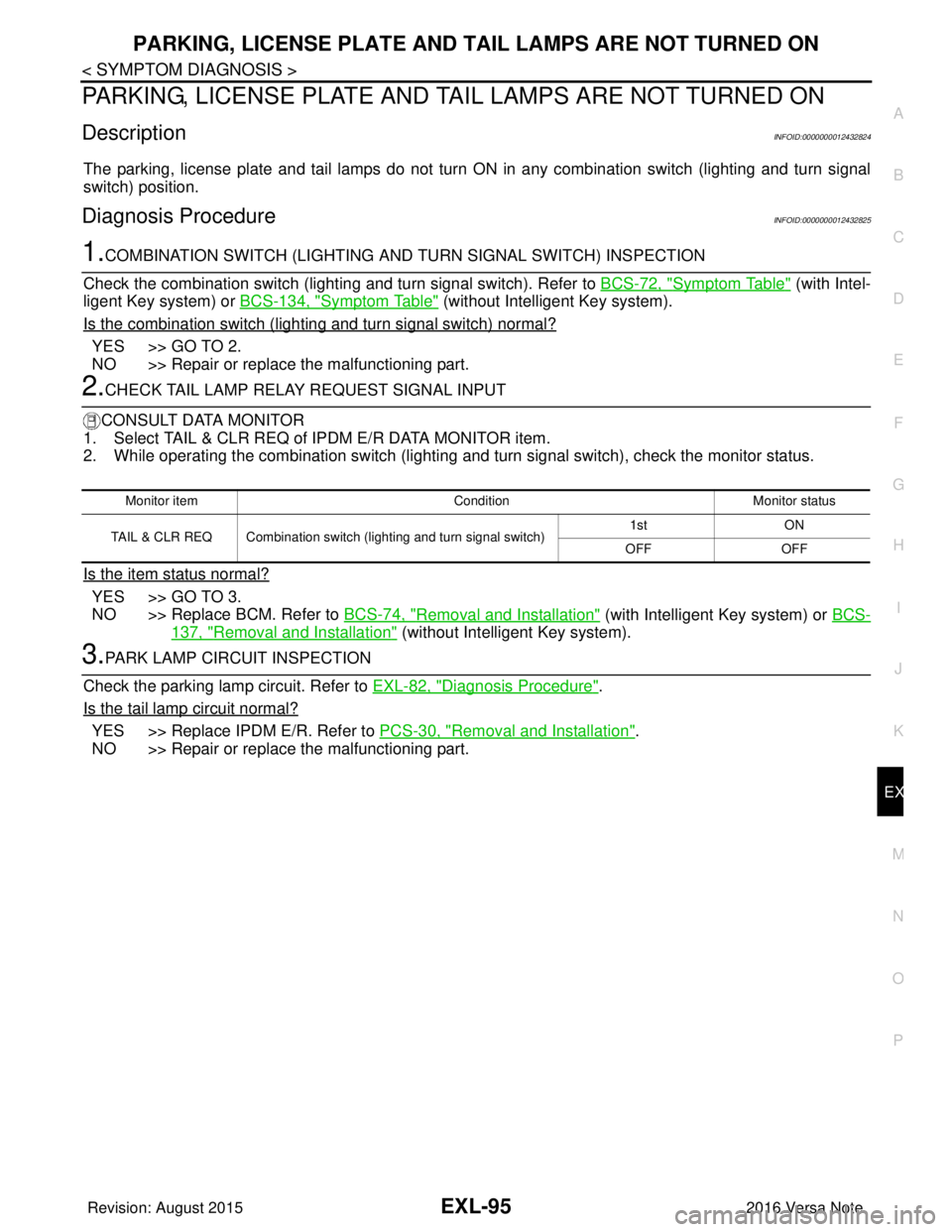
PARKING, LICENSE PLATE AND TA IL LAMPS ARE NOT TURNED ON
DescriptionINFOID:0000000012432824
The parking, license plate and tail lamps do not turn ON in any combination switch (lighting and turn signal
switch) position.
Diagnosis ProcedureINFOID:0000000012432825
1.COMBINATION SWITCH (LIGHTING AND TURN SIGNAL SWITCH) INSPECTION
Check the combination switch (lighti ng and turn signal switch). Refer to BCS-72, "
Symptom Table" (with Intel-
ligent Key system) or BCS-134, "
Symptom Table" (without Intelligent Key system).
Is the combination switch (lighting and turn signal switch) normal?
YES >> GO TO 2.
NO >> Repair or replace the malfunctioning part.
2.CHECK TAIL LAMP RELAY REQUEST SIGNAL INPUT
CONSULT DATA MONITOR
1. Select TAIL & CLR REQ of IPDM E/R DATA MONITOR item.
2. While operating the combination switch (lighting and turn signal switch), check the monitor status.
Is the item status normal?
YES >> GO TO 3.
NO >> Replace BCM. Refer to BCS-74, "
Removal and Installation" (with Intelligent Key system) or BCS-
137, "Removal and Installation" (without Intelligent Key system).
3.PARK LAMP CIRCUIT INSPECTION
Check the parking lamp circuit. Refer to EXL-82, "
Diagnosis Procedure".
Is the tail lamp circuit normal?
YES >> Replace IPDM E/R. Refer to PCS-30, "Removal and Installation".
NO >> Repair or replace the malfunctioning part.
Monitor item ConditionMonitor status
TAIL & CLR REQ Combination switch (lighting and turn signal switch) 1st
ON
OFF OFF
Revision: August 2015 2016 Versa Note
cardiagn.com
Page 1748 of 3641
EXL-96
< SYMPTOM DIAGNOSIS >
BOTH SIDE FRONT FOG LAMPS ARE NOT TURNED ON
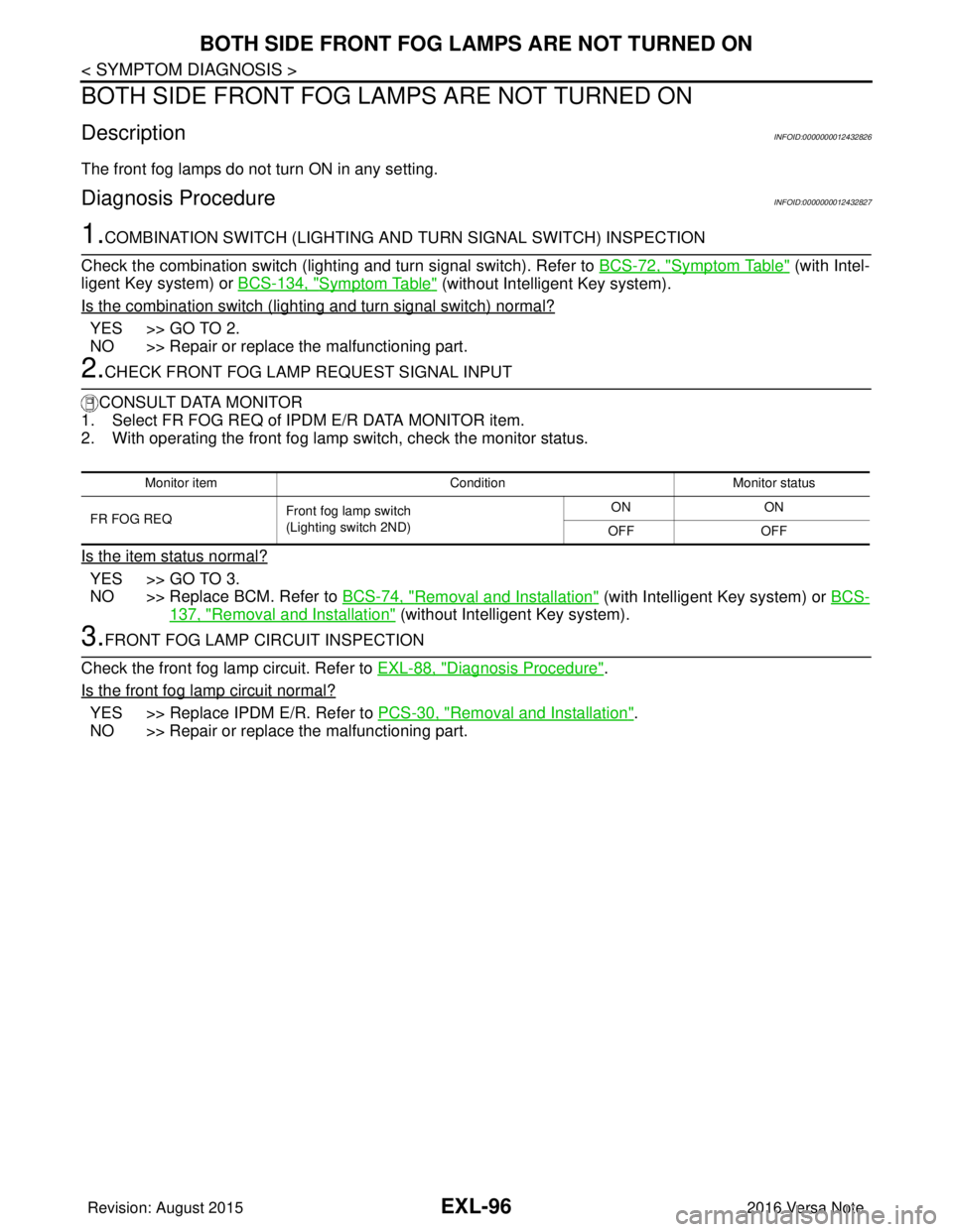
BOTH SIDE FRONT FOG LA MPS ARE NOT TURNED ON
DescriptionINFOID:0000000012432826
The front fog lamps do not turn ON in any setting.
Diagnosis ProcedureINFOID:0000000012432827
1.COMBINATION SWITCH (LIGHTING AND TURN SIGNAL SWITCH) INSPECTION
Check the combination switch (lighting and turn signal switch). Refer to BCS-72, "
Symptom Table" (with Intel-
ligent Key system) or BCS-134, "
Symptom Table" (without Intelligent Key system).
Is the combination switch (lighting and turn signal switch) normal?
YES >> GO TO 2.
NO >> Repair or replace the malfunctioning part.
2.CHECK FRONT FOG LAMP REQUEST SIGNAL INPUT
CONSULT DATA MONITOR
1. Select FR FOG REQ of IPDM E/R DATA MONITOR item.
2. With operating the front fog lamp switch, check the monitor status.
Is the item status normal?
YES >> GO TO 3.
NO >> Replace BCM. Refer to BCS-74, "
Removal and Installation" (with Intelligent Key system) or BCS-
137, "Removal and Installation" (without Intelligent Key system).
3.FRONT FOG LAMP CIRCUIT INSPECTION
Check the front fog lamp circuit. Refer to EXL-88, "
Diagnosis Procedure".
Is the front fog lamp circuit normal?
YES >> Replace IPDM E/R. Refer to PCS-30, "Removal and Installation".
NO >> Repair or replace the malfunctioning part.
Monitor item ConditionMonitor status
FR FOG REQ Front fog lamp switch
(Lighting switch 2ND) ON
ON
OFF OFF
Revision: August 2015 2016 Versa Note
cardiagn.com
Page 1889 of 3641

GI-1
GENERAL INFORMATION
C
DE
F
G H
I
J
K L
M B
GI
SECTION GI
N
O P
CONTENTS
GENERAL INFORMATION
HOW TO USE THIS MANU AL ......................3
HOW TO USE THIS MANUAL ....................... .....3
Description .......................................................... ......3
Terms ........................................................................3
Units ..........................................................................3
Contents ....................................................................3
Relation between Illustrations and Descriptions .......4
Components ..............................................................4
HOW TO FOLLOW TROUBLE DIAGNOSES .....6
Description ................................................................6
How to Follow Test Groups in Trouble Diagnosis ......6
Key to Symbols Signifying Measurements or Pro-
cedures ............................................................... ......
7
HOW TO READ WIRING DIAGRAMS ................9
Connector Symbols ............................................. ......9
Sample/Wiring Diagram -Example- .........................10
Connector Information .............................................12
ABBREVIATIONS .......................................... ....14
Abbreviation List .................................................. ....14
TIGHTENING TORQUE OF STANDARD
BOLTS ................................................................
19
Description .......................................................... ....19
Tightening Torque Table (New Standard Includ-
ed) ...........................................................................
19
RECOMMENDED CHEMICAL PRODUCTS
AND SEALANTS ................................................
22
Recommended Chemical Products and Sealants ....22
PRECAUTION ..............................................23
PRECAUTIONS .............................................. ....23
Description .......................................................... ....23
Precaution for Supplemental Restraint System
(SRS) "AIR BAG" and "SEAT BELT PRE-TEN-
SIONER" .................................................................
23
Procedures without Cowl Top Cover .......................23
Cautions in Removing Battery Terminal and AV
Control Unit (Models with AV Control Unit) .............
23
General Precautions ............................................ ....24
Three Way Catalyst .................................................25
Fuel ..........................................................................25
Multiport Fuel Injection System or Engine Control
System .....................................................................
26
Hoses ......................................................................26
Engine Oils ..............................................................27
Air Conditioning .......................................................27
LIFTING POINT .................................................28
Special Service Tool ................................................28
Garage Jack and Safety Stand ................................28
2-Pole Lift ................................................................29
Board-on Lift ............................................................30
TOW TRUCK TOWING .....................................31
Tow Truck Towing ...................................................31
Vehicle Recovery (Freeing a Stuck Vehicle) ...........31
VEHICLE INFORMATION ...........................33
IDENTIFICATION INFORMATION ....................33
Model Variation .................................................... ....33
Identification Number ...............................................34
Identification Plate ...................................................35
Engine Serial Number .............................................36
CVT Number ............................................................36
Manual Transaxle Number ......................................36
Dimensions ..............................................................36
Wheels & Tires ........................................................37
BASIC INSPECTION ...................................38
SERVICE INFORMATION FOR ELECTRICAL
INCIDENT ..........................................................
38
Work Flow ............................................................ ....38
Control Units and Electrical Parts ............................38
How to Check Terminal ...........................................39
Intermittent Incident ............................................. ....42
Circuit Inspection .....................................................44
Revision: August 2015 2016 Versa Note
cardiagn.com
Page 1895 of 3641
HOW TO FOLLOW TROUBLE DIAGNOSES
GI-7
< HOW TO USE THIS MANUAL >
C
D E
F
G H
I
J
K L
M B
GI
N
O P
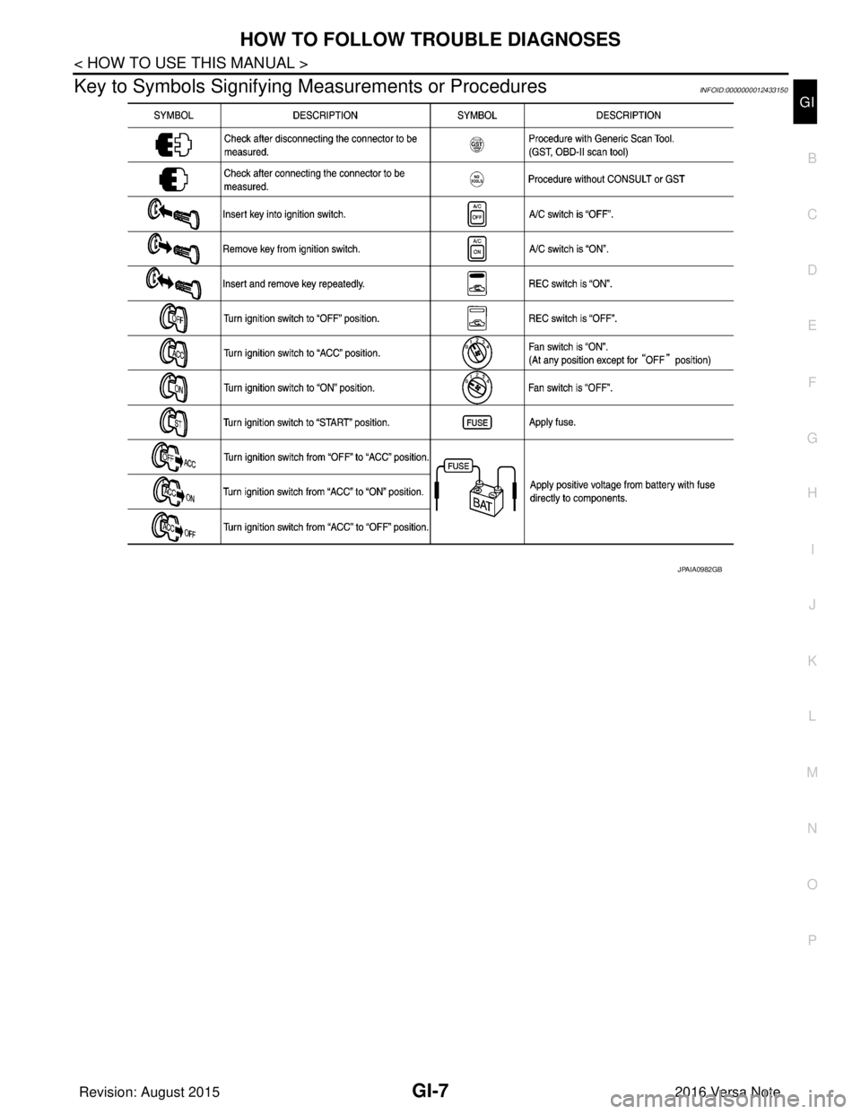
Key to Symbols Signifying Measurements or ProceduresINFOID:0000000012433150
JPAIA0982GB
Revision: August 2015 2016 Versa Note
cardiagn.com
Page 1913 of 3641
PRECAUTIONSGI-25
< PRECAUTION >
C
DE
F
G H
I
J
K L
M B
GI
N
O P
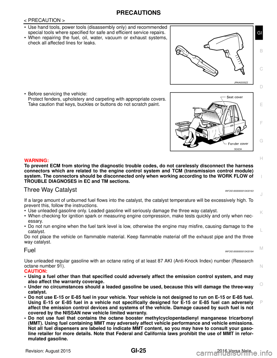
• Use hand tools, power tools (disassembly only) and recommended special tools where specified for safe and efficient service repairs.
• When repairing the fuel, oil, water, vacuum or exhaust systems,
check all affected lines for leaks.
• Before servicing the vehicle: Protect fenders, upholstery and carpeting with appropriate covers.
Take caution that keys, buckles or buttons do not scratch paint.
WARNING:
To prevent ECM from storing the diagnostic trou ble codes, do not carelessly disconnect the harness
connectors which are related to the engine cont rol system and TCM (transmission control module)
system. The connectors should be disconnected only when working according to the WORK FLOW of
TROUBLE DIAGNOSES in EC and TM sections.
Three Way CatalystINFOID:0000000012433163
If a large amount of unburned fuel flows into the catalyst, the catalyst temperature will be excessively high. To
prevent this, follow the instructions.
• Use unleaded gasoline only. Leaded gasoline will seriously damage the three way catalyst.
• When checking for ignition spark or measuring engine compression, make tests quickly and only when nec-
essary.
• Do not run engine when the fuel tank level is low, otherwise the engine may misfire, causing damage to the
catalyst.
Do not place the vehicle on flammable material. Keep flammable material off the exhaust pipe and the three
way catalyst.
FuelINFOID:0000000012433164
Use unleaded regular gasoline with an octane rating of at least 87 AKI (Anti-Knock Index) number (Research
octane number 91).
CAUTION:
• Using a fuel other than that specified could adversely affect th e emission control system, and may
also affect the warranty coverage.
• Under no circumstances should a leaded gasoline be used, because this will damage the three-way
catalyst.
• Do not use E-15 or E-85 fuel in your vehicle. Your vehicle is not designed to run on E-15 or E-85 fuel. Using E-15 or E-85 fuel in a vehicle not specifically designed for E-15 or E-85 fuel can adversely
affect the emission control devices and systems of the vehicle. Damage caused by such fuel is not
covered by the NISSAN new vehicle limited warranty.
• Do not use fuel that contains the octane boo ster methylcyclopentadienyl manganese tricarbonyl
(MMT). Using fuel containing MM T may adversely affect vehicle pe rformance and vehicle emissions.
Not all fuel dispensers are labeled to indicate MMT content, so you may have to consult your gaso-
line retailer for more details. Note that Federal and California laws prohibit the use of MMT in refor-
mulated gasoline.
JPAIA0335ZZ
SGI234
Revision: August 2015 2016 Versa Note
cardiagn.com
Page 1919 of 3641
TOW TRUCK TOWINGGI-31
< PRECAUTION >
C
DE
F
G H
I
J
K L
M B
GI
N
O PTOW TRUCK TOWING
To w T r u c k To w i n gINFOID:0000000012433173
CAUTION:
• Never tow a CVT model with the rear wheels raised and the front wheels on the ground. This may
cause serious and expensive damage to the transaxle. If it is necessary to tow the vehicle with the
rear wheels raised, always use towin g dollies under the front wheels.
• Never tow a CVT model from the rear (that is b ackward) with four wheels on the ground. This may
cause serious and expensive damage to the transaxle.
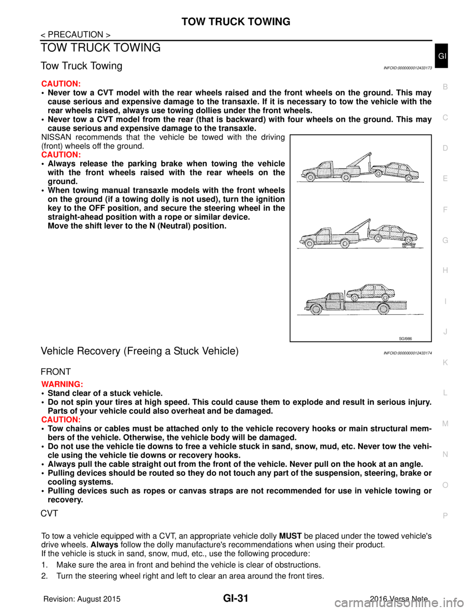
NISSAN recommends that the vehicle be towed with the driving
(front) wheels off the ground.
CAUTION:
• Always release the parking br ake when towing the vehicle
with the front wheels raised with the rear wheels on the
ground.
• When towing manual transaxle models with the front wheels on the ground (if a towing dolly is not used), turn the ignition
key to the OFF position, and secu re the steering wheel in the
straight-ahead position with a rope or similar device.
Move the shift lever to th e N (Neutral) position.
Vehicle Recovery (Freeing a Stuck Vehicle)INFOID:0000000012433174
FRONT
WARNING:
• Stand clear of a stuck vehicle.
• Do not spin your tires at high speed. This could cause them to explode and result in serious injury.
Parts of your vehicle could also overheat and be damaged.
CAUTION:
• Tow chains or cables must be attached only to the vehicle recovery hooks or main structural mem-
bers of the vehicle. Otherwise, the vehicle body will be damaged.
• Do not use the vehicle tie downs to free a vehicle stuck in sand, snow, mud, etc. Never tow the vehi-
cle using the vehicle tie downs or recovery hooks.
• Always pull the cable straight out from the front of the vehicle. Never pull on the hook at an angle.
• Pulling devices should be routed so they do not touch any part of the suspension, steering, brake or
cooling systems.
• Pulling devices such as ropes or canvas straps ar e not recommended for use in vehicle towing or
recovery.
CVT
To tow a vehicle equipped with a CVT, an appropriate vehicle dolly MUST be placed under the towed vehicle's
drive wheels. Always follow the dolly manufacture's re commendations when using their product.
If the vehicle is stuck in sand, snow , mud, etc., use the following procedure:
1. Make sure the area in front and behind the vehicle is clear of obstructions.
2. Turn the steering wheel right and left to clear an area around the front tires.
SGI986
Revision: August 2015 2016 Versa Note
cardiagn.com
Page 1926 of 3641
GI-38
< BASIC INSPECTION >
SERVICE INFORMATION FOR ELECTRICAL INCIDENT
BASIC INSPECTION
SERVICE INFORMATION FOR ELECTRICAL INCIDENT
Work FlowINFOID:0000000012433183
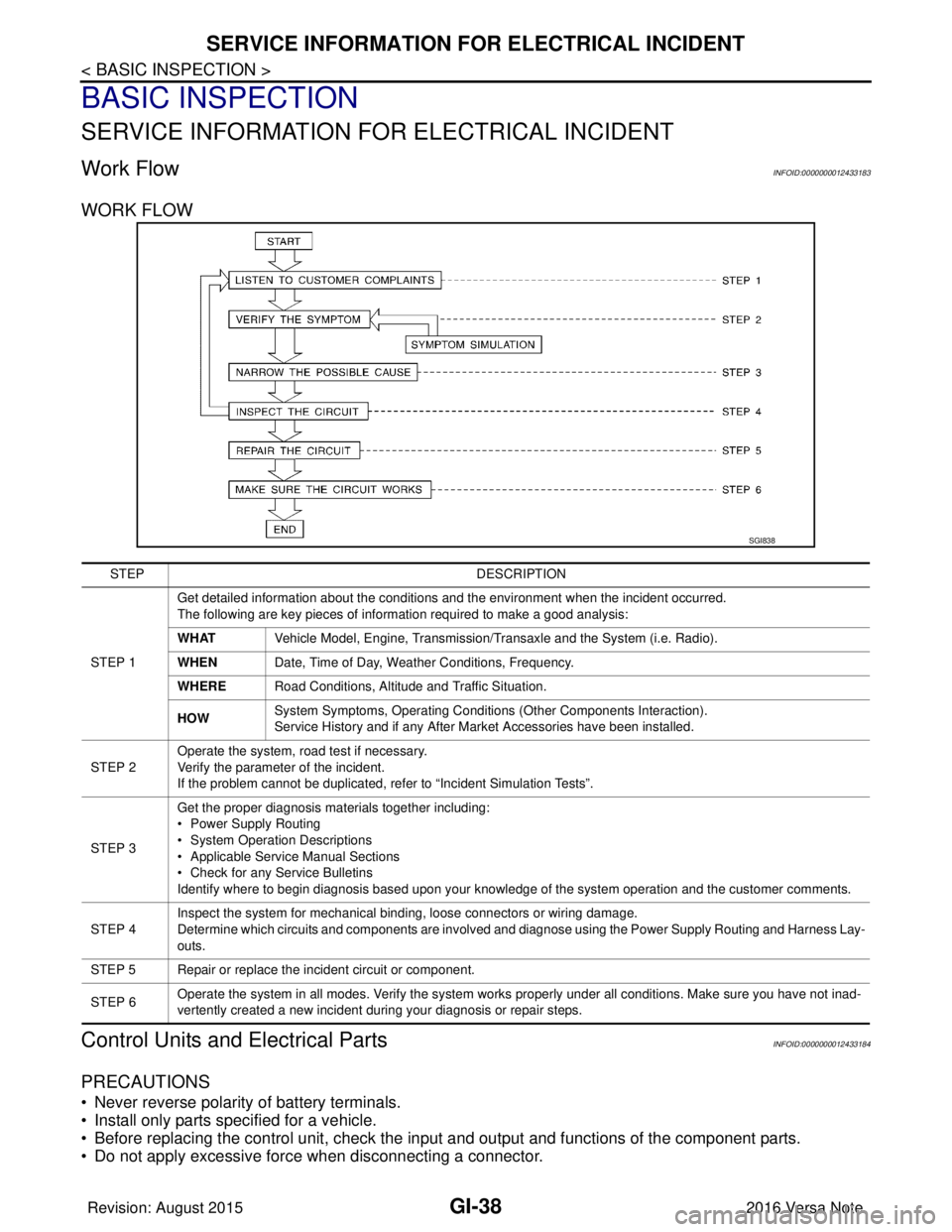
WORK FLOW
Control Units and Electrical PartsINFOID:0000000012433184
PRECAUTIONS
• Never reverse polarity of battery terminals.
• Install only parts specified for a vehicle.
• Before replacing the control unit, check the i nput and output and functions of the component parts.
• Do not apply excessive force when disconnecting a connector.
SGI838
STEP DESCRIPTION
STEP 1 Get detailed information about the conditions and the environment when the incident occurred.
The following are key pieces of information required to make a good analysis:
WHAT
Vehicle Model, Engine, Transmission/Transaxle and the System (i.e. Radio).
WHEN Date, Time of Day, Weather Conditions, Frequency.
WHERE Road Conditions, Altitude and Traffic Situation.
HOW System Symptoms, Operating Conditions
(Other Components Interaction).
Service History and if any After Market Accessories have been installed.
STEP 2 Operate the system, road test if necessary.
Verify the parameter of the incident.
If the problem cannot be duplicated, refer to “Incident Simulation Tests”.
STEP 3 Get the proper diagnosis materials together including:
• Power Supply Routing
• System Operation Descriptions
• Applicable Service Manual Sections
• Check for any Service Bulletins
Identify where to begin diagnosis based upon your knowledge of the system operation and the customer comments.
STEP 4 Inspect the system for mechanical binding, loose connectors or wiring damage.
Determine which circuits and components are involved and diagnose using the Power Supply Routing and Harness Lay-
outs.
STEP 5 Repair or replace the incident circuit or component.
STEP 6 Operate the system in all modes. Verify the system works properly under all conditions. Make sure you have not inad-
vertently created a new incident during your diagnosis or repair steps.
Revision: August 2015
2016 Versa Note
cardiagn.com
Page 1934 of 3641

GI-46
< BASIC INSPECTION >
SERVICE INFORMATION FOR ELECTRICAL INCIDENT
Resistance Check Method
• Disconnect the battery negative cable and remove the blown fuse.
• Disconnect all loads (SW1 open, relay disconnected and solenoid disconnected) powered through the fuse.
• Connect one probe of the DMM to the load side of the fuse terminal. Connect the other probe to a knowngood ground.
• With SW1 open, check for continuity. continuity; short is between fuse terminal and SW1 (point A).
no continuity; short is further down the circuit than SW1.
• Close SW1 and disconnect the relay. Put probes at the load side of fuse terminal and a known good ground. Then, check for continuity.
continuity; short is between SW1 and the relay (point B).
no continuity; short is further down the circuit than the relay.
• Close SW1 and jump the relay contacts with jumper wire. Put probes at the load side of fuse terminal and a known good ground. Then, check for continuity.
continuity; short is between relay and solenoid (point C).
no continuity; check solenoid, retrace steps.
Voltage Check Method
• Remove the blown fuse and disconnect all loads (i.e. SW1 open, relay disconnected and solenoid discon-
nected) powered through the fuse.
• Turn the ignition key to the ON or START position. Verify battery voltage at the battery + side of the fuse ter- minal (one lead on the battery + terminal side of the fuse block and one lead on a known good ground).
• With SW1 open and the DMM leads across both fuse terminals, check for voltage. voltage; short is between fuse block and SW1 (point A).
no voltage; short is further down the circuit than SW1.
• With SW1 closed, relay and solenoid disconnected and the DMM leads across both fuse terminals, check for voltage.
voltage; short is between SW1 and the relay (point B).
no voltage; short is further down the circuit than the relay.
• With SW1 closed, relay contacts jumped with fused jumper wire check for voltage. voltage; short is down the circuit of the relay or between the relay and the disconnected solenoid (point C).
no voltage; retrace steps and check power to fuse block.
GROUND INSPECTION
• Ground connections are very important to the proper operation of electrical and electronic circuits. Ground
connections are often exposed to moisture, dirt and other corrosive elements. The corrosion (rust) can
become an unwanted resistance. This unwanted resistance can change the way a circuit works.
• Electronically controlled circuits are very sens itive to proper grounding. A loose or corroded ground can
drastically affect an electronically controlled circuit. A poor or corroded ground can easily affect the circuit.
Even when the ground connection looks clean, there c an be a thin film of rust on the surface.
• When inspecting a ground connection follow these rules:
- Remove the ground bolt or screw.
- Inspect all mating surfaces for tarnish, dirt, rust, etc.
- Clean as required to assure good contact.
- Reinstall bolt or screw securely.
- Inspect for “add-on” accessories which may be interfering with the ground circuit.
- If several wires are crimped into one ground eyelet terminal, check for proper crimps. Make sure all of the
wires are clean, securely fastened and providing a good ground path. If multiple wires are cased in one eye-
let make sure no ground wires have excess wire insulation.
Revision: August 2015 2016 Versa Note
cardiagn.com