2016 NISSAN NOTE warning
[x] Cancel search: warningPage 3546 of 3641
WCS
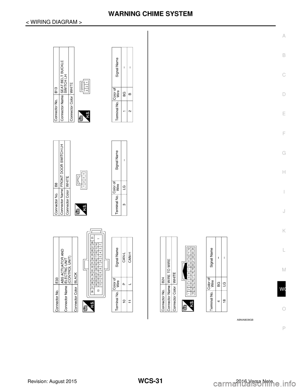
WARNING CHIME SYSTEMWCS-31
< WIRING DIAGRAM >
C
DE
F
G H
I
J
K L
M B A
O P
ABNIA8039GB
Revision: August 2015 2016 Versa Note
cardiagn.com
Page 3548 of 3641

WCS
DIAGNOSIS AND REPAIR WORK FLOWWCS-33
< BASIC INSPECTION >
C
DE
F
G H
I
J
K L
M B A
O P
1. Connect CONSULT and perform self-diagnosis. Refer to MWI-24, "DTC Index" (Type A) or MWI-77, "DTC
Index" (Type B).
2. When DTC is detected, follow the instructions below:
- Record DTC and Freeze Frame Data.
Are self-diagnosis results normal?
YES >> GO TO 4.
NO >> GO TO 5.
4.NARROW DOWN MALFUNCTIONING PARTS BY SYMPTOM DIAGNOSIS
Perform symptom diagnosis and narrow down the malfunctioning parts.
>> GO TO 5.
5.REPAIR OR REPLACE MALFUNCTIONING PARTS
Repair or replace malfunctioning parts.
NOTE:
If DTC is displayed, erase DTC after repairing or replacing malfunctioning parts.
>> GO TO 6.
6.FINAL CHECK
Check that the warning buzzer in the combination meter operates normally.
Does it operate normally?
YES >> Inspection End.
NO >> GO TO 1.
Revision: August 2015 2016 Versa Note
cardiagn.com
Page 3557 of 3641
WCS-42
< DTC/CIRCUIT DIAGNOSIS >
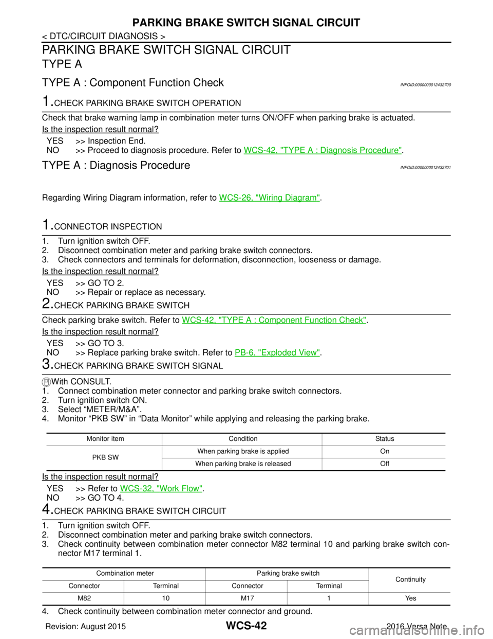
PARKING BRAKE SWITCH SIGNAL CIRCUIT
PARKING BRAKE SWITCH SIGNAL CIRCUIT
TYPE A
TYPE A : Component Function CheckINFOID:0000000012432700
1.CHECK PARKING BRAKE SWITCH OPERATION
Check that brake warning lamp in combination me ter turns ON/OFF when parking brake is actuated.
Is the inspection result normal?
YES >> Inspection End.
NO >> Proceed to diagnosis procedure. Refer to WCS-42, "
TYPE A : Diagnosis Procedure".
TYPE A : Diagnosis ProcedureINFOID:0000000012432701
Regarding Wiring Diagram information, refer to WCS-26, "Wiring Diagram".
1.CONNECTOR INSPECTION
1. Turn ignition switch OFF.
2. Disconnect combination meter and parking brake switch connectors.
3. Check connectors and terminals for deformation, disconnection, looseness or damage.
Is the inspection result normal?
YES >> GO TO 2.
NO >> Repair or replace as necessary.
2.CHECK PARKING BRAKE SWITCH
Check parking brake switch. Refer to WCS-42, "
TYPE A : Component Function Check".
Is the inspection result normal?
YES >> GO TO 3.
NO >> Replace parking brake switch. Refer to PB-6, "
Exploded View".
3.CHECK PARKING BRAKE SWITCH SIGNAL
With CONSULT.
1. Connect combination meter connector and parking brake switch connectors.
2. Turn ignition switch ON.
3. Select “METER/M&A”.
4. Monitor “PKB SW” in “Data Monitor” while applying and releasing the parking brake.
Is the inspection result normal?
YES >> Refer to WCS-32, "Work Flow".
NO >> GO TO 4.
4.CHECK PARKING BRAKE SWITCH CIRCUIT
1. Turn ignition switch OFF.
2. Disconnect combination meter and parking brake switch connectors.
3. Check continuity between combination meter connec tor M82 terminal 10 and parking brake switch con-
nector M17 terminal 1.
4. Check continuity between combination meter connector and ground.
Monitor item Condition Status
PKB SW When parking brake is applied
On
When parking brake is released Off
Combination meterParking brake switch
Continuity
Connector TerminalConnector Terminal
M82 10 M171Yes
Revision: August 2015 2016 Versa Note
cardiagn.com
Page 3558 of 3641
WCS
PARKING BRAKE SWITCH SIGNAL CIRCUITWCS-43
< DTC/CIRCUIT DIAGNOSIS >
C
DE
F
G H
I
J
K L
M B A
O P
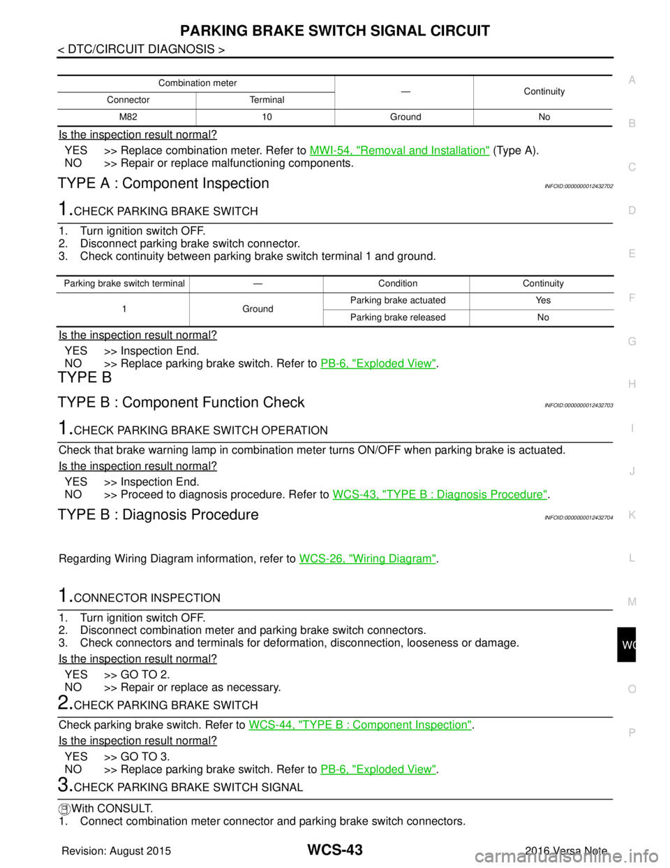
Is the inspection result normal?
YES >> Replace combination meter. Refer to MWI-54, "Removal and Installation" (Type A).
NO >> Repair or replace malfunctioning components.
TYPE A : Component InspectionINFOID:0000000012432702
1.CHECK PARKING BRAKE SWITCH
1. Turn ignition switch OFF.
2. Disconnect parking brake switch connector.
3. Check continuity between parking brake switch terminal 1 and ground.
Is the inspection result normal?
YES >> Inspection End.
NO >> Replace parking brake switch. Refer to PB-6, "
Exploded View".
TYPE B
TYPE B : Component Function CheckINFOID:0000000012432703
1.CHECK PARKING BRA KE SWITCH OPERATION
Check that brake warning lamp in combination meter turns ON/OFF when parking brake is actuated.
Is the inspection result normal?
YES >> Inspection End.
NO >> Proceed to diagnosis procedure. Refer to WCS-43, "
TYPE B : Diagnosis Procedure".
TYPE B : Diagnosis ProcedureINFOID:0000000012432704
Regarding Wiring Diagram information, refer to WCS-26, "Wiring Diagram".
1.CONNECTOR INSPECTION
1. Turn ignition switch OFF.
2. Disconnect combination meter and parking brake switch connectors.
3. Check connectors and terminals for deformation, disconnection, looseness or damage.
Is the inspection result normal?
YES >> GO TO 2.
NO >> Repair or replace as necessary.
2.CHECK PARKING BRAKE SWITCH
Check parking brake switch. Refer to WCS-44, "
TYPE B : Component Inspection".
Is the inspection result normal?
YES >> GO TO 3.
NO >> Replace parking brake switch. Refer to PB-6, "
Exploded View".
3.CHECK PARKING BRAKE SWITCH SIGNAL
With CONSULT.
1. Connect combination meter connector and parking brake switch connectors.
Combination meter —Continuity
Connector Terminal
M82 10 Ground No
Parking brake switch terminal —Condition Continuity
1 GroundParking brake actuated
Yes
Parking brake released No
Revision: August 2015 2016 Versa Note
cardiagn.com
Page 3562 of 3641
WCS
THE PARKING BRAKE RELEASE WARNING CONTINUES SOUNDING, OR
DOES NOT SOUND
WCS-47
< SYMPTOM DIAGNOSIS >
C
DE
F
G H
I
J
K L
M B A
O P
SYMPTOM DIAGNOSIS
THE PARKING BRAKE RELEASE WARN ING CONTINUES SOUNDING, OR
DOES NOT SOUND
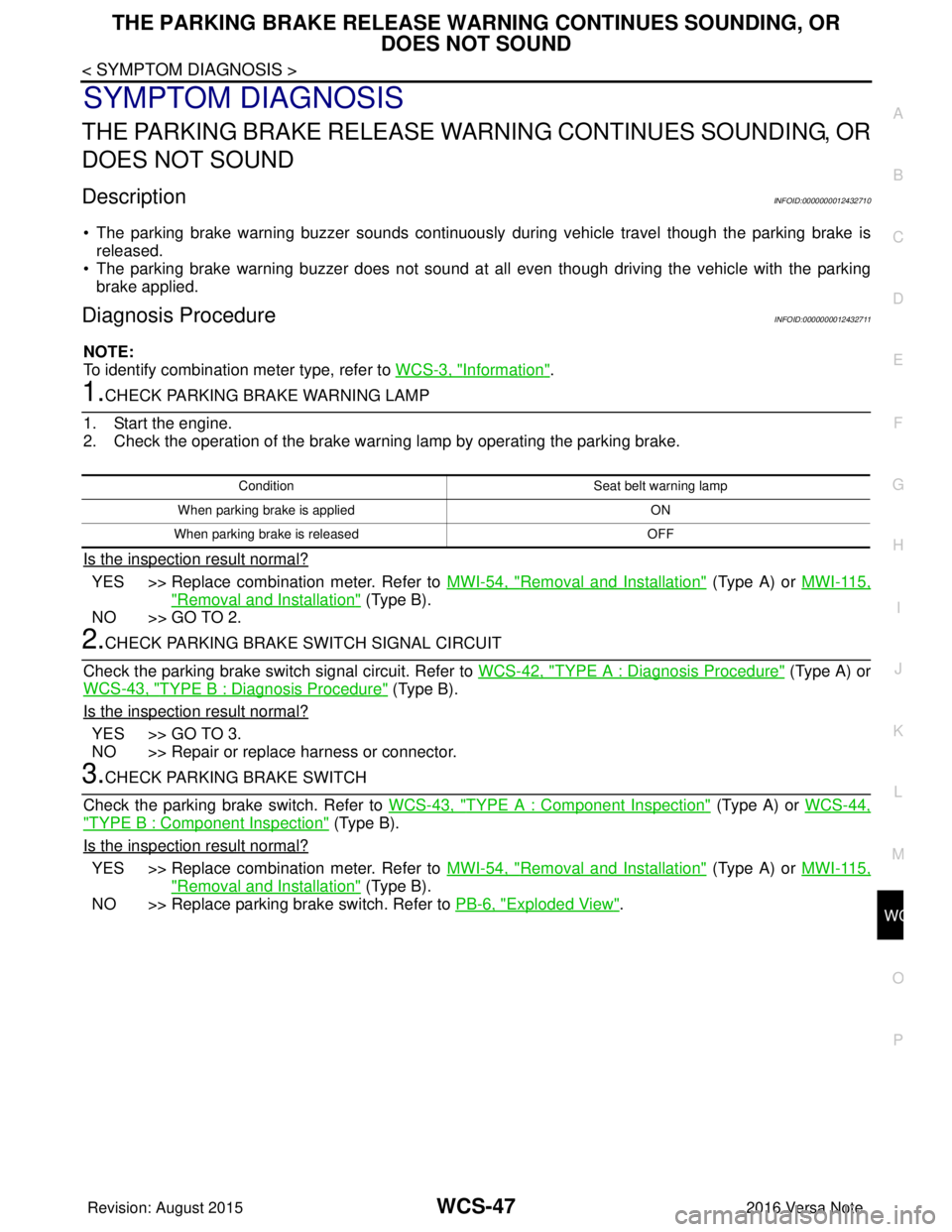
DescriptionINFOID:0000000012432710
• The parking brake warning buzzer sounds continuously during vehicle travel though the parking brake is
released.
• The parking brake warning buzzer does not sound at all even though driving the vehicle with the parking brake applied.
Diagnosis ProcedureINFOID:0000000012432711
NOTE:
To identify combination meter type, refer to WCS-3, "
Information".
1.CHECK PARKING BRAKE WARNING LAMP
1. Start the engine.
2. Check the operation of the brake warning lamp by operating the parking brake.
Is the inspection result normal?
YES >> Replace combination meter. Refer to MWI-54, "Removal and Installation" (Type A) or MWI-115,
"Removal and Installation" (Type B).
NO >> GO TO 2.
2.CHECK PARKING BRAKE SWITCH SIGNAL CIRCUIT
Check the parking brake switch signal circuit. Refer to WCS-42, "
TYPE A : Diagnosis Procedure" (Type A) or
WCS-43, "
TYPE B : Diagnosis Procedure" (Type B).
Is the inspection result normal?
YES >> GO TO 3.
NO >> Repair or replace harness or connector.
3.CHECK PARKING BRAKE SWITCH
Check the parking brake switch. Refer to WCS-43, "
TYPE A : Component Inspection" (Type A) or WCS-44,
"TYPE B : Component Inspection" (Type B).
Is the inspection result normal?
YES >> Replace combination meter. Refer to MWI-54, "Removal and Installation" (Type A) or MWI-115,
"Removal and Installation" (Type B).
NO >> Replace parking brake switch. Refer to PB-6, "
Exploded View".
Condition Seat belt warning lamp
When parking brake is applied ON
When parking brake is released OFF
Revision: August 2015 2016 Versa Note
cardiagn.com
Page 3563 of 3641
WCS-48
< SYMPTOM DIAGNOSIS >
THE SEAT BELT REMINDER WARNING CONTINUES SOUNDING, OR DOES
NOT SOUND
THE SEAT BELT REMINDER WARN ING CONTINUES SOUNDING, OR
DOES NOT SOUND
DescriptionINFOID:0000000012432712
• Seat belt reminder warning does not sound.
• Seat belt reminder warning sounds continuously.
Diagnosis ProcedureINFOID:0000000012432713
NOTE:
To identify combination meter type, refer to WCS-3, "
Information".
1.CHECK WARNING CHIME OPERATION
1. Select “BUZZER” of “BCM” using CONSULT.
2. Perform “SEAT BELT WARN TEST” in “Active Test”.
Is the inspection result normal?
YES >> GO TO 2.
NO >> Replace combination meter. Refer to MWI-54, "
Removal and Installation" (Type A) or MWI-115,
"Removal and Installation" (Type B).
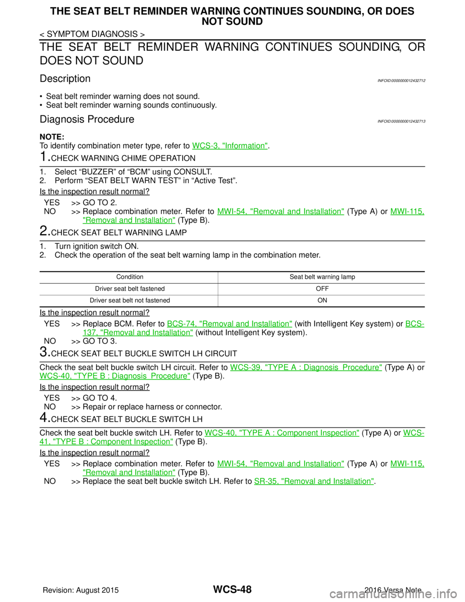
2.CHECK SEAT BELT WARNING LAMP
1. Turn ignition switch ON.
2. Check the operation of the seat belt warning lamp in the combination meter.
Is the inspection result normal?
YES >> Replace BCM. Refer to BCS-74, "Removal and Installation" (with Intelligent Key system) or BCS-
137, "Removal and Installation" (without Intelligent Key system).
NO >> GO TO 3.
3.CHECK SEAT BELT BUCKLE SWITCH LH CIRCUIT
Check the seat belt buckle switch LH circuit. Refer to WCS-39, "
TYPE A : DiagnosisProcedure" (Type A) or
WCS-40, "
TYPE B : DiagnosisProcedure" (Type B).
Is the inspection result normal?
YES >> GO TO 4.
NO >> Repair or replace harness or connector.
4.CHECK SEAT BELT BUCKLE SWITCH LH
Check the seat belt buckle switch LH. Refer to WCS-40, "
TYPE A : Component Inspection" (Type A) or WCS-
41, "TYPE B : Component Inspection" (Type B).
Is the inspection result normal?
YES >> Replace combination meter. Refer to MWI-54, "Removal and Installation" (Type A) or MWI-115,
"Removal and Installation" (Type B).
NO >> Replace the seat belt buckle switch LH. Refer to SR-35, "
Removal and Installation".
Condition Seat belt warning lamp
Driver seat belt fastened OFF
Driver seat belt not fastened ON
Revision: August 2015 2016 Versa Note
cardiagn.com
Page 3564 of 3641
WCS
THE LIGHT REMINDER WARNING DOES NOT SOUNDWCS-49
< SYMPTOM DIAGNOSIS >
C
DE
F
G H
I
J
K L
M B A
O P
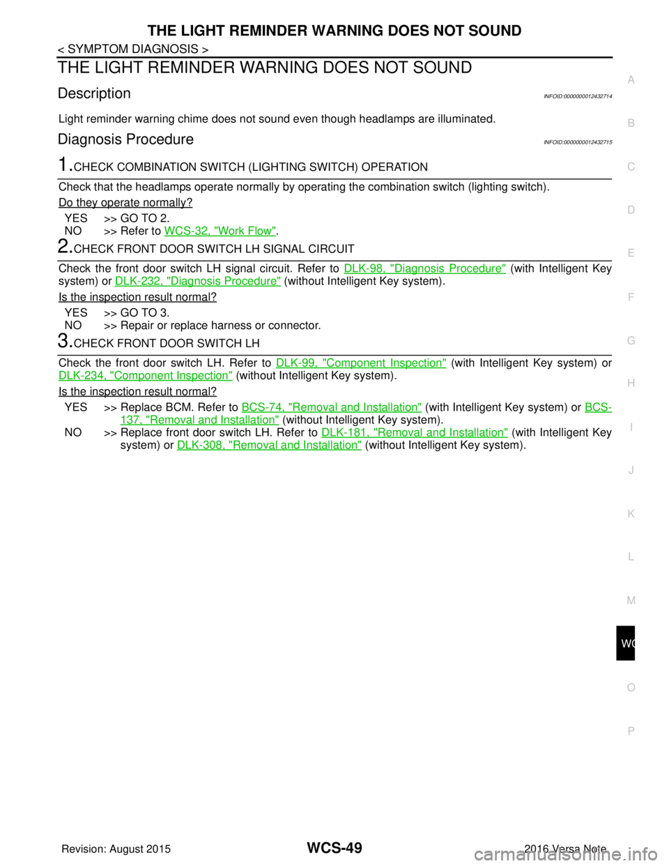
THE LIGHT REMINDER WA RNING DOES NOT SOUND
DescriptionINFOID:0000000012432714
Light reminder warning chime does not sound even though headlamps are illuminated.
Diagnosis ProcedureINFOID:0000000012432715
1.CHECK COMBINATION SWITCH (L IGHTING SWITCH) OPERATION
Check that the headlamps operate normally by operat ing the combination switch (lighting switch).
Do they operate normally?
YES >> GO TO 2.
NO >> Refer to WCS-32, "
Work Flow".
2.CHECK FRONT DOOR SWITCH LH SIGNAL CIRCUIT
Check the front door switch LH signal circuit. Refer to DLK-98, "
Diagnosis Procedure" (with Intelligent Key
system) or DLK-232, "
Diagnosis Procedure" (without Intelligent Key system).
Is the inspection result normal?
YES >> GO TO 3.
NO >> Repair or replace harness or connector.
3.CHECK FRONT DOOR SWITCH LH
Check the front door switch LH. Refer to DLK-99, "
Component Inspection" (with Intelligent Key system) or
DLK-234, "
Component Inspection" (without Intelligent Key system).
Is the inspection result normal?
YES >> Replace BCM. Refer to BCS-74, "Removal and Installation" (with Intelligent Key system) or BCS-
137, "Removal and Installation" (without Intelligent Key system).
NO >> Replace front door switch LH. Refer to DLK-181, "
Removal and Installation" (with Intelligent Key
system) or DLK-308, "
Removal and Installation" (without Intelligent Key system).
Revision: August 2015 2016 Versa Note
cardiagn.com
Page 3565 of 3641
WCS-50
< SYMPTOM DIAGNOSIS >
THE KEY WARNING DOES NOT SOUND (WITHOUT INTELLIGENT KEY)
THE KEY WARNING DOES NOT SOUN D (WITHOUT INTELLIGENT KEY)
DescriptionINFOID:0000000012432716
The key warning chime does not sound, when all of the following conditions are fulfilled.
• Key inserted into the key cylinder (key switch signal ON).
• Ignition switch is in ACC or OFF (ignition switch signal OFF).
• Driver side door is open (front door switch LH ON)
Diagnosis ProcedureINFOID:0000000012432717
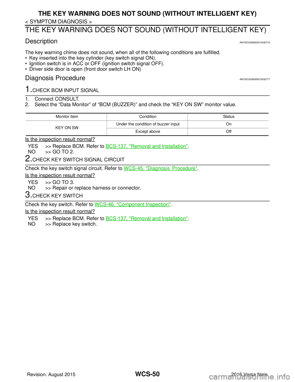
1.CHECK BCM INPUT SIGNAL
1. Connect CONSULT.
2. Select the “Data Monitor” of “BCM (BUZZER)” and check t he “KEY ON SW” monitor value.
Is the inspection result normal?
YES >> Replace BCM. Refer to BCS-137, "Removal and Installation".
NO >> GO TO 2.
2.CHECK KEY SWITCH SIGNAL CIRCUIT
Check the key switch signal circuit. Refer to WCS-45, "
DiagnosisProcedure".
Is the inspection result normal?
YES >> GO TO 3.
NO >> Repair or replace harness or connector.
3.CHECK KEY SWITCH
Check the key switch. Refer to WCS-46, "
Component Inspection".
Is the inspection result normal?
YES >> Replace BCM. Refer to BCS-137, "Removal and Installation".
NO >> Replace key switch.
Monitor item Condition Status
KEY ON SW Under the condition of buzzer input
On
Except above Off
Revision: August 2015 2016 Versa Note
cardiagn.com