2016 NISSAN NOTE oil level
[x] Cancel search: oil levelPage 1903 of 3641

ABBREVIATIONSGI-15
< HOW TO USE THIS MANUAL >
C
DE
F
G H
I
J
K L
M B
GI
N
O P
E
F
G
H
DLC Data link connector
DTC Diagnostic trouble code
ABBREVIATION DESCRIPTION
E/T Exhaust temperature
EBD Electric brake force distribution
EC Engine control
ECL Engine coolant level
ECM Engine control module
ECT Engine coolant temperature
ECV Electrical control valve
EEPROM Electrically erasable programmable read only memory EFT Engine fuel temperature
EGR Exhaust gas recirculation
EGRT Exhaust gas recirculation temperature EGT Exhaust gas temperature
EOP Engine oil pressure
EP Exhaust pressure
EPR Exhaust pressure regulator
EPS Electronically controlled power steering
ESP Electronic stability program system
EVAP canister Evaporative emission canister EVSE Electric vehicle supply equipment
EXC Exhaust control
ABBREVIATION DESCRIPTION
FC Fan control
FCW Forward collision warning
FIC Fuel injector control
FP Fuel pump
FR Front
FRP Fuel rail pressure
FRT Fuel rail temperature
FTP Fuel tank pressure
FTT Fuel tank temperature
ABBREVIATION DESCRIPTION
GND Ground
GPS Global positioning system
GST Generic scan tool
ABBREVIATION DESCRIPTION
HBMC Hydraulic body-motion control system HDD Hard disk drive
HO2S Heated oxygen sensor
ABBREVIATION
DESCRIPTION
Revision: August 2015 2016 Versa Note
cardiagn.com
Page 1912 of 3641

GI-24
< PRECAUTION >
PRECAUTIONS
General Precautions
INFOID:0000000012433162
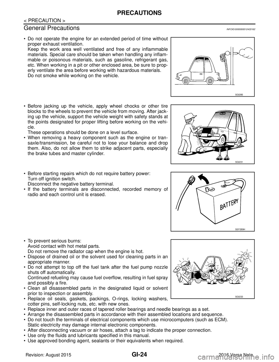
• Do not operate the engine for an extended period of time without proper exhaust ventilation.
Keep the work area well ventilated and free of any inflammable
materials. Special care should be taken when handling any inflam-
mable or poisonous materials, such as gasoline, refrigerant gas,
etc. When working in a pit or other enclosed area, be sure to prop-
erly ventilate the area before working with hazardous materials.
Do not smoke while working on the vehicle.
• Before jacking up the vehicle, apply wheel chocks or other tire blocks to the wheels to prevent the vehicle from moving. After jack-
ing up the vehicle, support the vehicle weight with safety stands at
the points designated for proper lifting before working on the vehi-
cle.
These operations should be done on a level surface.
• When removing a heavy component such as the engine or tran- saxle/transmission, be careful not to lose your balance and drop
them. Also, do not allow them to strike adjacent parts, especially
the brake tubes and master cylinder.
• Before starting repairs which do not require battery power: Turn off ignition switch.
Disconnect the negative battery terminal.
• If the battery terminals are disconnected, recorded memory of radio and each control unit is erased.
• To prevent serious burns: Avoid contact with hot metal parts.
Do not remove the radiator cap when the engine is hot.
• Dispose of drained oil or the solvent used for cleaning parts in an appropriate manner.
• Do not attempt to top off the fuel tank after the fuel pump nozzle
shuts off automatically.
Continued refueling may cause fuel overflow, resulting in fuel spray
and possibly a fire.
• Clean all disassembled parts in the designated liquid or solvent prior to inspection or assembly.
• Replace oil seals, gaskets, packings, O-rings, locking washers,
cotter pins, self-locking nuts, etc. with new ones.
• Replace inner and outer races of tapered roller bearings and needle bearings as a set.
• Arrange the disassembled parts in accordance with their assembled locations and sequence.
• Do not touch the terminals of electrical com ponents which use microcomputers (such as ECM).
Static electricity may damage internal electronic components.
• After disconnecting vacuum or air hoses, atta ch a tag to indicate the proper connection.
• Use only the fluids and lubricants specified in this manual.
• Use approved bonding agent, sealants or their equivalents when required.
SGI285
SGI231
SEF289H
SGI233
Revision: August 2015 2016 Versa Note
cardiagn.com
Page 1913 of 3641

PRECAUTIONSGI-25
< PRECAUTION >
C
DE
F
G H
I
J
K L
M B
GI
N
O P
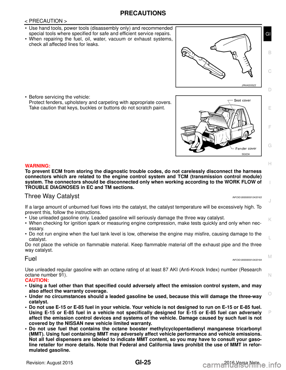
• Use hand tools, power tools (disassembly only) and recommended special tools where specified for safe and efficient service repairs.
• When repairing the fuel, oil, water, vacuum or exhaust systems,
check all affected lines for leaks.
• Before servicing the vehicle: Protect fenders, upholstery and carpeting with appropriate covers.
Take caution that keys, buckles or buttons do not scratch paint.
WARNING:
To prevent ECM from storing the diagnostic trou ble codes, do not carelessly disconnect the harness
connectors which are related to the engine cont rol system and TCM (transmission control module)
system. The connectors should be disconnected only when working according to the WORK FLOW of
TROUBLE DIAGNOSES in EC and TM sections.
Three Way CatalystINFOID:0000000012433163
If a large amount of unburned fuel flows into the catalyst, the catalyst temperature will be excessively high. To
prevent this, follow the instructions.
• Use unleaded gasoline only. Leaded gasoline will seriously damage the three way catalyst.
• When checking for ignition spark or measuring engine compression, make tests quickly and only when nec-
essary.
• Do not run engine when the fuel tank level is low, otherwise the engine may misfire, causing damage to the
catalyst.
Do not place the vehicle on flammable material. Keep flammable material off the exhaust pipe and the three
way catalyst.
FuelINFOID:0000000012433164
Use unleaded regular gasoline with an octane rating of at least 87 AKI (Anti-Knock Index) number (Research
octane number 91).
CAUTION:
• Using a fuel other than that specified could adversely affect th e emission control system, and may
also affect the warranty coverage.
• Under no circumstances should a leaded gasoline be used, because this will damage the three-way
catalyst.
• Do not use E-15 or E-85 fuel in your vehicle. Your vehicle is not designed to run on E-15 or E-85 fuel. Using E-15 or E-85 fuel in a vehicle not specifically designed for E-15 or E-85 fuel can adversely
affect the emission control devices and systems of the vehicle. Damage caused by such fuel is not
covered by the NISSAN new vehicle limited warranty.
• Do not use fuel that contains the octane boo ster methylcyclopentadienyl manganese tricarbonyl
(MMT). Using fuel containing MM T may adversely affect vehicle pe rformance and vehicle emissions.
Not all fuel dispensers are labeled to indicate MMT content, so you may have to consult your gaso-
line retailer for more details. Note that Federal and California laws prohibit the use of MMT in refor-
mulated gasoline.
JPAIA0335ZZ
SGI234
Revision: August 2015 2016 Versa Note
cardiagn.com
Page 1973 of 3641
![NISSAN NOTE 2016 Service Repair Manual PRECAUTIONSHAC-5
< PRECAUTION > [MANUAL AIR CONDITIONING]
C
D
E
F
G H
J
K L
M A
B
HAC
N
O P
• When the compressor is removed, store it in th e same way as it is when mounted on the vehicle.
Failure NISSAN NOTE 2016 Service Repair Manual PRECAUTIONSHAC-5
< PRECAUTION > [MANUAL AIR CONDITIONING]
C
D
E
F
G H
J
K L
M A
B
HAC
N
O P
• When the compressor is removed, store it in th e same way as it is when mounted on the vehicle.
Failure](/manual-img/5/57363/w960_57363-1972.png)
PRECAUTIONSHAC-5
< PRECAUTION > [MANUAL AIR CONDITIONING]
C
D
E
F
G H
J
K L
M A
B
HAC
N
O P
• When the compressor is removed, store it in th e same way as it is when mounted on the vehicle.
Failure to do so will cause oil to enter the low-pressure chamber.
• Use always a torque wrench and a b ack-up wrench when connecting tubes.
• Plug immediately all openings to prevent entry of dust and mois ture after disconnecting tubes.
• Connect the pipes at the final stag e of the operation when installing an air conditioner in the vehicle.
Do not remove the seal caps of pipes and other comp onents until just before required for connec-
tion.
• Allow components stored in cool areas to warm to working area temperature before removing seal
caps. This prevents condensation from forming inside A/C components.
• Remove thoroughly moisture from the refriger ation system before charging the refrigerant.
• Replace always used O-rings.
• Apply oil to the O-rings shown in illustrations wh en connecting tubes. Be careful not to apply oil to
threaded portion.
• O-ring must be closely attached to the groove portion of tube.
• Be careful not to damage O-ring and tube when replacing the O-ring.
• Connect tube until a click can be heard. Then tighten the nut or bolt by hand. Check that the O-ring is
installed to tube correctly.
• Perform leak test and make sure there are no leaks from connections after connecting lines. Discon-
nect that line and replace the O-ring when the refrigerant leak point is found. Then tighten connec-
tions of seal seat to the specified torque.
COMPRESSOR
CAUTION:
• Plug all openings to prevent moisture and foreign matter from entering.
• When the compressor is removed, store it in the same way as it is when mounted on the vehicle.
• Follow “MAINTENANCE OF OIL LEVEL” exactly when replacing or repairing compressor. Refer to HA-22, "
Description".
• Keep friction surfaces between clutch and pulley clean . Wipe them off by using a clean waste cloth
moistened with solvent if the su rfaces are contaminated with oil.
• Turn the compressor shaft by hand more than fi ve turns in both directions after compressor service
operation. This equally distribut es oil inside the compressor. Let the engine idle and operate the
compressor for one hour after the compressor is installed.
• After replacing the compressor magnet clutch, appl y voltage to the new clutch to check for normal
operation.
LEAK DETECTION DYE
CAUTION:
• The A/C system contains a fluorescent leak detect ion dye used for locating refrigerant leaks. An
ultraviolet (UV) lamp is required to il luminate the dye when inspecting for leaks.
• Always wear fluorescence enhancing UV safety goggles to protect eyes and enhance the visibility of
the fluorescent dye. Name : A/C System Oil Type: DH-PR
RHA861F
Revision: August 2015
2016 Versa Note
cardiagn.com
Page 2031 of 3641

HA-6
< PRECAUTION >
PRECAUTIONS
• The air conditioner warranty is void if the vehicle is within the warranty period. Please contact Nissan Cus-tomer Affairs for further assistance.
COMPRESSOR
CAUTION:
• Cap or plug all openings to prevent moisture and fo reign matter from entering.
• Store it in the same way as it is when moun ted on the car when the compressor is removed.
• Follow “Maintenance of Oil Level” exactly when replacing or repairing compressor. Refer to HA-22,
"Description".
• Keep friction surfaces between clut ch and pulley clean. Wipe it off by using a clean waste cloth
moistened with thinner if the su rface is contaminated with oil.
• Turn the compressor shaft by hand more than five turns in both directions after compressor service
operation. This distributes oil e qually inside the compressor. Let the engine idle and operate the
compressor for one hour after the compressor is installed.
• Apply voltage to the new one and check for norma l operation after replacing the compressor magnet
clutch.
LEAK DETECTION DYE
CAUTION:
• The A/C system contains a fluorescent leak detect ion dye used for locating refrigerant leaks. An
ultraviolet (UV) lamp is required to il luminate the dye when inspecting for leaks.
• Always wear fluorescence enhancing UV safety goggles to protect eyes and enhance the visibility of the fluorescent dye.
• The fluorescent dye leak detector is not a replacement for an electrical l eak detector (SST: J-41995).
The fluorescent dye leak detector sh ould be used in conjunction with an electrical leak detector
(SST: J-41995) to pin-point refrigerant leaks.
• Read and follow all manufacture’s operating inst ructions and precautions prior to performing the
work for the purpose of safet y and customer’s satisfaction.
• A compressor shaft seal should not necessarily be repaired becau se of dye seepage. The compres-
sor shaft seal should only be repaired after confi rming the leak with an electrical leak detector (SST:
J-41995).
• Always remove any remaining dye from the leak area after repairs are completed to avoid a misdiag-
nosis during a future service.
• Do not allow dye to come into contact with painted body panels or interior components. Clean imme- diately with the approved dye cl eaner if dye is spilled. Fluorescent dye left on a surface for an
extended period of time cannot be removed.
• Do not spray the fluorescent dye cleaning agent on hot surfaces (engine exhaust manifold, etc.).
• Do not use more than one refrigerant dye bottle [1/4 ounce (7.4 cc)] per A/C system.
• Leak detection dyes for HFC-134a (R-134a) and CFC-12 (R-12) A/C systems are different. Do not use
HFC-134a (R-134a) leak detection dye in CFC-12 (R- 12) A/C system or CFC-12 (R-12) leak detection
dye in HFC-134a (R-134a) A/C system or A/C system damage may result.
• The fluorescent properties of the dye remains fo r three or more years unless a compressor malfunc-
tion occurs.
NOTE: Identification
• Vehicles with factory installed fluorescent dye have a green label.
• Vehicles without factory installed fluorescent dye have a blue label.
Service EquipmentINFOID:0000000012431988
RECOVERY/RECYCLING RECHARGING EQUIPMENT
Be certain to follow the manufacturer’s instructions for machine operation and machine maintenance. Do not
introduce any refrigerant other than that specified into the machine.
ELECTRONIC LEAK DETECTOR
Be certain to follow the manufacturer’s instruct ions for tester operation and tester maintenance.
VACUUM PUMP
Revision: August 2015 2016 Versa Note
cardiagn.com
Page 2046 of 3641

REFRIGERANTHA-21
< PERIODIC MAINTENANCE >
C
DE
F
G H
J
K L
M A
B
HA
N
O P
2. Operate recovery/recycling/recharging equipment, and evacuate air from A/C system for 25 minutes or more.
CAUTION:
Evacuate air for 15 minutes or more if parts are replaced.
3. Check the airtightness of A/C system for 25 minutes or more. If pressure raises more than the specified
level, charge A/C system with approximately 200g of refrigerant and check that there are no refrigerant
leaks. Refer to HA-18, "
Leak Test".
CAUTION:
Check the airtightness for 15 minutes or more if parts are replaced.
4. If parts other than the compressor are replaced, fill compressor oil according to parts that are replaced.
Refer to HA-22, "
Oil Adjusting Procedure for Components Replacement Except Compressor".
5. Charge the specified amount of refrigerant into A/C system.
6. Check that the A/C system operates normally.
7. Collect the refrigerant from the high-pressure hos e and low-pressure hose of recovery/recycling/recharg-
ing equipment. Disconnect recovery/recycling/recharging equipment.
8. Install A/C service valve caps.
9. Refrigerant charge is complete.
Revision: August 2015 2016 Versa Note
cardiagn.com
Page 2047 of 3641

HA-22
< PERIODIC MAINTENANCE >
OIL
OIL
DescriptionINFOID:0000000012432001
MAINTENANCE OF OIL LEVEL
The compressor oil circulates in the system together with the refrigerant. It is necessary to add oil to the com-
pressor when replacing A/C system components or when a large amount of refrigerant leaks from the system.
It is important to always maintain oil level within t he specified level. Otherwise, the following conditions may
occur.
• Insufficient oil amount: Stuck compressor
• Excessive oil amount: Insufficient cooling (caused by insufficient heat exchange)
InspectionINFOID:0000000012432002
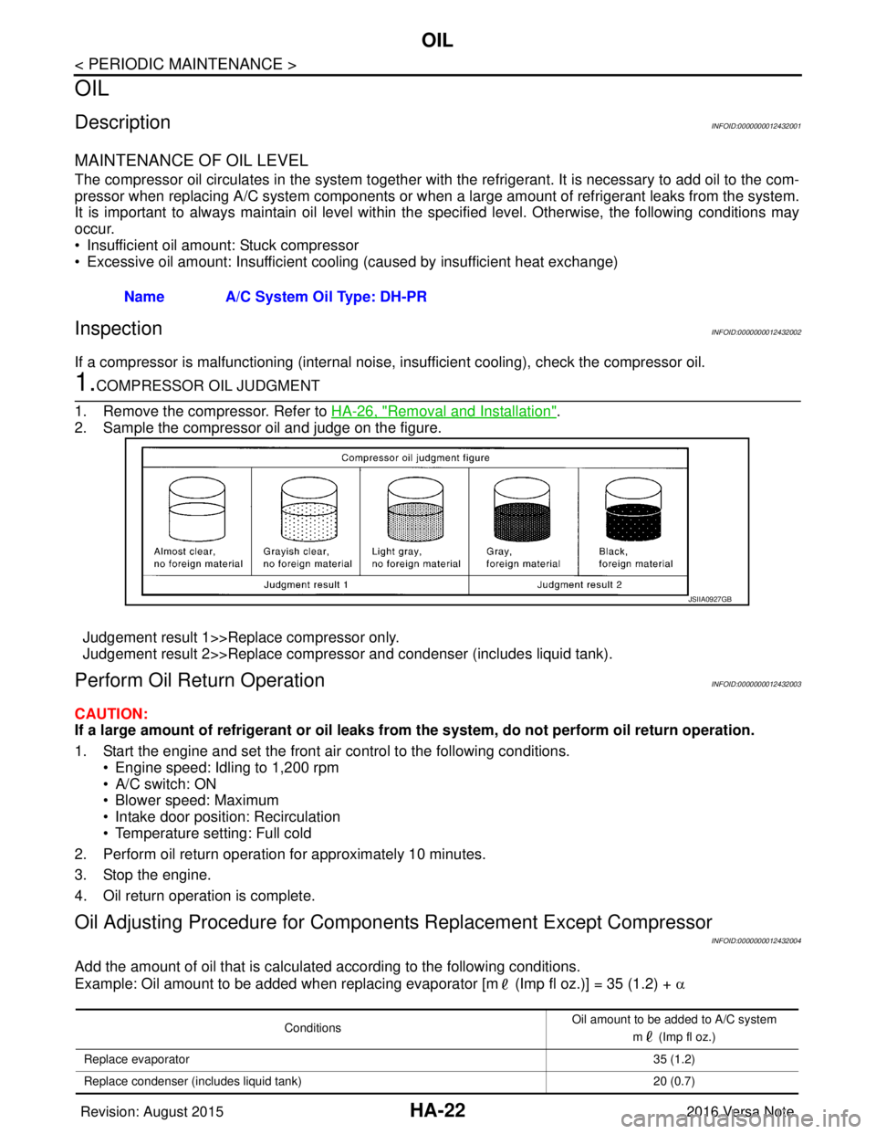
If a compressor is malfunctioning (internal noise, insufficient cooling), check the compressor oil.
1.COMPRESSOR OIL JUDGMENT
1. Remove the compressor. Refer to HA-26, "
Removal and Installation".
2. Sample the compressor oil and judge on the figure.
Judgement result 1>>Replace compressor only.
Judgement result 2>>Replace compressor and condenser (includes liquid tank).
Perform Oil Retu rn OperationINFOID:0000000012432003
CAUTION:
If a large amount of refrigerant or oil leaks from the system, do not perform oil return operation.
1. Start the engine and set the front air control to the following conditions. • Engine speed: Idling to 1,200 rpm
• A/C switch: ON
• Blower speed: Maximum
• Intake door position: Recirculation
• Temperature setting: Full cold
2. Perform oil return operation for approximately 10 minutes.
3. Stop the engine.
4. Oil return operation is complete.
Oil Adjusting Procedure for Compon ents Replacement Except Compressor
INFOID:0000000012432004
Add the amount of oil that is calculated according to the following conditions.
Example: Oil amount to be added when replacing evaporator [m (Imp fl oz.)] = 35 (1.2) + α
Name A/C System Oil Type: DH-PR
JSIIA0927GB
Conditions
Oil amount to be added to A/C system
m (Imp fl oz.)
Replace evaporator 35 (1.2)
Replace condenser (includes liquid tank) 20 (0.7)
Revision: August 20152016 Versa Note
cardiagn.com
Page 2321 of 3641

MA-6
< PERIODIC MAINTENANCE >
GENERAL MAINTENANCE
UNDER THE HOOD AND VEHICLE
The maintenance items listed here should be checked periodically (e.g. each time you check the engine oil or refuel).
SeatsCheck seat position controls such as seat adjusters, seatback recliner, etc. to
make sure they operate smoothly and that all latches lock securely in every po-
sition. Check that the head restraints move up and down smoothly and that the
locks (if equipped) hold securely in all latched positions. Check that the latches
lock securely for folding-down rear seatbacks. —
Seat belts Check that all parts of the seat belt system (e.g. buckles, anchors, adjusters and
retractors) operate properly and smoothly and are installed securely. Check the
belt webbing for cuts, fraying, wear or damage. MA-43
Accelerator pedal
Check the pedal for smooth operation and make sure the pedal does not catch
or require uneven effort. Keep the floor mats away from the pedal. —
Brakes Check that the brake does not pull the vehicle to one side when applied. —
Brake pedal and
booster Check the pedal for smooth operation and make sure it has the proper distance
under it when depressed fully. Check the brake booster function. Be sure to keep
floor mats away from the pedal. BR-9
Clutch pedal
Make sure the pedal operates smoothly and check that it has the proper free play. CL-5
Parking brakeCheck that the lever or pedal has the proper travel and make sure that the vehicle
is held securely on a fairly steep hill when only the parking brake is applied. PB-4
CVT "P" (Park) posi-
tion mechanismOn a fairly steep hill check that the vehicle is held securely with the shift selector
in the "P" (PARK) position without applying any brakes.
—
Item
Reference page
Item Reference page
Windshield washer
fluid Check that there is adequate fluid in the tank.
—
Engine coolant level Check the coolant level when the engine is cold. CO-8
Radiator and hosesCheck the front of the radiator and clean off any dirt, insects, leaves, etc., that
may have accumulated. Make sure the radiator hoses have no cracks, deforma-
tion, deterioration or loose connections. CO-12
Brake and clutch fluid
levelsMake sure that the brake and clutch fluid levels are between the “MAX” and “MIN”
lines on the reservoirs. BR-12
CL-7
Battery
Check the fluid level in each cell. It should be between the “MAX” and “MIN” lines.
Vehicles operated in high temperatures or under severe conditions require fre-
quent checks of the battery fluid level. PG-61
Engine drive belts
Make sure that no belt is frayed, worn, cracked or oily. MA-14
Engine oil levelCheck the level on the oil level gauge after parking the vehicle on a level spot and
turning off the engine. MA-20
Exhaust system
Make sure there are no loose supports, cracks or holes. If the sound of the ex-
haust seems unusual or there is a smell of exhaust fumes, immediately locate the
trouble and correct it. MA-26
Underbody
The underbody is frequently exposed to corrosive substances such as those
used on icy roads or to control dust. It is very important to remove these sub-
stances, otherwise rust will form on the floor pan, frame, fuel lines and around the
exhaust system. At the end of winter, the underbody should be thoroughly
flushed with plain water, being careful to clean those areas where mud and dirt
can easily accumulate. —
Fluid leaks Check under the vehicle for fuel, oil, water or other fluid leaks after the vehicle
has been parked for a while. Water dripping from the air conditioner after use is
normal. If you should notice any leaks or gasoline fumes are evident, check for
the cause and correct it immediately. —
Revision: August 2015
2016 Versa Note
cardiagn.com