2016 NISSAN NOTE belt
[x] Cancel search: beltPage 414 of 3641

BODY COMPONENT PARTSBRM-15
< PREPARATION >
C
DE
F
G H
I
J
L
M A
B
BRM
N
O P
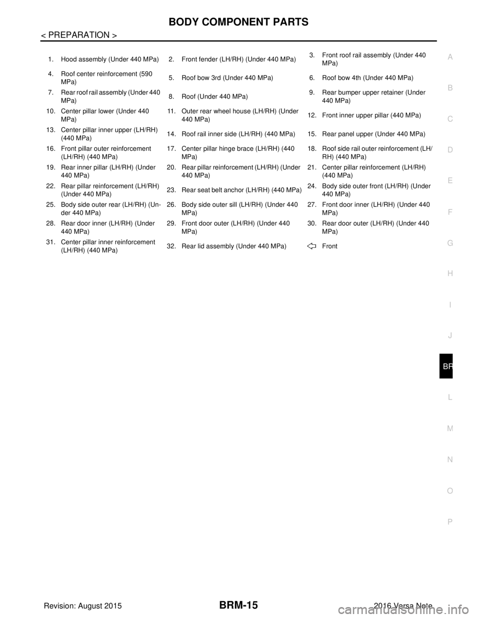
1. Hood assembly (Under 440 MPa) 2. Front fender (LH/RH) (Under 440 MPa) 3. Front roof rail assembly (Under 440
MPa)
4. Roof center reinforcement (590 MPa) 5. Roof bow 3rd (Under 440 MPa)
6. Roof bow 4th (Under 440 MPa)
7. Rear roof rail assembly (Under 440 MPa) 8. Roof (Under 440 MPa)
9. Rear bumper upper retainer (Under
440 MPa)
10. Center pillar lo wer (Under 440
MPa) 11. Outer rear wheel house (LH/RH) (Under
440 MPa) 12. Front inner upper pillar (440 MPa)
13. Center pillar in ner upper (LH/RH)
(440 MPa) 14. Roof rail inner side (LH/RH) (440 MPa) 15. Rear panel upper (Under 440 MPa)
16. Front pillar ou ter reinforcement
(LH/RH) (440 MPa) 17. Center pillar hinge brace (LH/RH) (440
MPa) 18. Roof side rail outer reinforcement (LH/
RH) (440 MPa)
19. Rear inner pillar (LH/RH) (Under 440 MPa) 20. Rear pillar reinforcement (LH/RH) (Under
440 MPa) 21. Center pillar reinforcement (LH/RH)
(440 MPa)
22. Rear pillar reinforcement (LH/RH) (Under 440 MPa) 23. Rear seat belt anchor (LH/RH) (440 MPa) 24. Body side outer front (LH/RH) (Under
440 MPa)
25. Body side outer rear (LH/RH) (Un- der 440 MPa) 26. Body side outer sill (LH/RH) (Under 440
MPa) 27. Front door inner (LH/RH) (Under 440
MPa)
28. Rear door inner (LH/RH) (Under 440 MPa) 29. Front door outer (LH/RH) (Under 440
MPa) 30. Rear door outer (LH/RH) (Under 440
MPa)
31. Center pillar inner reinforcement (LH/RH) (440 MPa) 32. Rear lid assembly (Under 440 MPa)
Front
Revision: August 2015 2016 Versa Note
cardiagn.com
Page 449 of 3641

BRC-1
BRAKES
C
DE
G H
I
J
K L
M
SECTION BRC
A
B
BRC
N
O P
CONTENTS
BRAKE CONTROL SYSTEM
VDC/TCS/ABS
PRECAUTION ....... ........................................
4
PRECAUTIONS .............................................. .....4
Precaution for Supplemental Restraint System
(SRS) "AIR BAG" and "SEAT BELT PRE-TEN-
SIONER" ............................................................. ......
4
Precaution for Brake System ....................................4
Precaution for Brake Control System ........................5
Precaution for Harness Re pair ..................................5
PREPARATION ............................................6
PREPARATION .............................................. .....6
Special Service Tool ........................................... ......6
Commercial Service Tool ..........................................6
SYSTEM DESCRIPTION ..............................7
COMPONENT PARTS ................................... .....7
Component Parts Location .................................. ......7
Component Description .............................................8
ABS Actuator and Electric Unit (Control Unit) ...........8
Wheel Sensor and Sensor Rotor ..............................9
Stop Lamp Switch .....................................................9
Steering Angle Sensor ..............................................9
VDC OFF Switch .....................................................10
Brake Fluid Level Switch .........................................10
Parking Brake Switch ..............................................10
SYSTEM .............................................................11
VDC/TCS/ABS ....................................................... ....11
VDC/TCS/ABS : System Diagram ...........................11
VDC/TCS/ABS : System De scription ......................11
VDC/TCS/ABS : VDC Functi on ...............................22
VDC/TCS/ABS : TCS Function ........... ....................24
VDC/TCS/ABS : ABS Function ........................... ....26
VDC/TCS/ABS : EBD Functi on ...............................27
VDC/TCS/ABS : Fail-safe ......................... ..............28
DIAGNOSIS SYSTEM [ABS ACTUATOR
AND ELECTRIC UNIT (CONTROL UNIT)] .......
31
CONSULT Function (ABS) .................................. ....31
ECU DIAGNOSIS INFORMATION ..............36
ABS ACTUATOR AND ELECTRIC UNIT
(CONTROL UNIT) .............................................
36
Reference Value .................................................. ....36
Fail-safe ...................................................................39
DTC Inspection Priority Chart ..................................42
DTC Index ...............................................................43
WIRING DIAGRAM ......................................44
BRAKE CONTROL SYSTEM ...........................44
Wiring Diagram .................................................... ....44
BASIC INSPECTION ...................................52
DIAGNOSIS AND REPAIR WORK FLOW .......52
Work Flow ............................................................ ....52
Diagnostic Work Sheet ............................................53
INSPECTION AND ADJUSTMENT ..................55
ADDITIONAL SERVICE WHEN REPLACING
CONTROL UNIT .................................................... ....
55
ADDITIONAL SERVICE WHEN REPLACING
CONTROL UNIT : Description .................................
55
ADDITIONAL SERVICE WHEN REPLACING
CONTROL UNIT : Special Repair Requirement ......
55
ADJUSTMENT OF STEERING ANGLE SENSOR
NEUTRAL POSITION ............................................ ....
55
ADJUSTMENT OF STEERING ANGLE SENSOR
NEUTRAL POSITION : Description .........................
55
ADJUSTMENT OF STEERING ANGLE SENSOR
NEUTRAL POSITION : Special Repair Require-
ment .........................................................................
55
CALIBRATION OF DECEL G SENSOR ................ ....56
Revision: August 2015 2016 Versa Note
cardiagn.com
Page 452 of 3641
![NISSAN NOTE 2016 Service Repair Manual BRC-4
< PRECAUTION >[VDC/TCS/ABS]
PRECAUTIONS
PRECAUTION
PRECAUTIONS
Precaution for Supplemental Restraint Syst
em (SRS) "AIR BAG" and "SEAT BELT
PRE-TENSIONER"
INFOID:0000000012430820
The Supplement NISSAN NOTE 2016 Service Repair Manual BRC-4
< PRECAUTION >[VDC/TCS/ABS]
PRECAUTIONS
PRECAUTION
PRECAUTIONS
Precaution for Supplemental Restraint Syst
em (SRS) "AIR BAG" and "SEAT BELT
PRE-TENSIONER"
INFOID:0000000012430820
The Supplement](/manual-img/5/57363/w960_57363-451.png)
BRC-4
< PRECAUTION >[VDC/TCS/ABS]
PRECAUTIONS
PRECAUTION
PRECAUTIONS
Precaution for Supplemental Restraint Syst
em (SRS) "AIR BAG" and "SEAT BELT
PRE-TENSIONER"
INFOID:0000000012430820
The Supplemental Restraint System such as “A IR BAG” and “SEAT BELT PRE-TENSIONER”, used along
with a front seat belt, helps to reduce the risk or severity of injury to the driver and front passenger for certain
types of collision. Information necessary to service the system safely is included in the SR and SB section of
this Service Manual.
WARNING:
• To avoid rendering the SRS inopera tive, which could increase the risk of personal injury or death in
the event of a collision which would result in air bag inflation, all maintenance must be performed by
an authorized NISSAN/INFINITI dealer.
• Improper maintenance, including in correct removal and installation of the SRS, can lead to personal
injury caused by unintent ional activation of the system. For re moval of Spiral Cable and Air Bag
Module, see the SR section.
• Do not use electrical test equipmen t on any circuit related to the SRS unless instructed to in this
Service Manual. SRS wiring harn esses can be identified by yellow and/or orange harnesses or har-
ness connectors.
PRECAUTIONS WHEN USING POWER TOOLS (AIR OR ELECTRIC) AND HAMMERS
WARNING:
• When working near the Airbag Diagnosis Sensor Unit or other Airbag System sensors with the Igni-
tion ON or engine running, DO NOT use air or electri c power tools or strike near the sensor(s) with a
hammer. Heavy vibration could activate the sensor( s) and deploy the air bag(s), possibly causing
serious injury.
• When using air or electric power tools or hammers , always switch the Ignition OFF, disconnect the
battery and wait at least three minutes before performing any service.
Precaution for Brake SystemINFOID:0000000012430821
WARNING:
Clean any dust from the front brake and rear brake using a vacuum dust collector. Do not blow by
compressed air.
• Brake fluid use refer to MA-11, "
Fluids and Lubricants".
• Do not reuse drained brake fluid.
• Do not spill or splash brake fluid on painted surfaces. Brake fluid may seriously damage paint. Wipe it off
immediately and wash with water if it gets on a painted surface.
• Always confirm the specified tightening torque when installing the brake pipes.
• After pressing the brake pedal more deeply or harder t han normal driving, such as air bleeding, check each
item of brake pedal. Adjust brake pedal if it is outside the standard value.
• Do not use mineral oils such as gasoline or light oil to clean. They may damage rubber parts and cause
improper operation.
• Always loosen the brake tube flare nut with a flare nut wrench.
• Tighten the brake tube flare nut to the specified torque with a crow-
foot (A) and torque wrench (B).
• Always connect the battery terminal when moving the vehicle.
• Turn the ignition switch OFF and disconnect the ABS actuator and electric unit (control unit) harness connector or the battery negative
terminal before performing the work.
• Check that no brake fluid leakage is present after replacing the parts.
JPFIA0001ZZ
Revision: August 2015 2016 Versa Note
cardiagn.com
Page 596 of 3641

CHG
CHG-1
ELECTRICAL & POWER CONTROL
C
DE
F
G H
I
J
K L
B
SECTION CHG
A
O P
N
CONTENTS
CHARGING SYSTEM
PRECAUTION .......
........................................3
PRECAUTIONS .............................................. .....3
Precaution for Supplemental Restraint System
(SRS) "AIR BAG" and "SEAT BELT PRE-TEN-
SIONER" ............................................................. ......
3
Precaution for Power Generation Voltage Variable
Control System ..........................................................
3
PREPARATION ............................................4
PREPARATION .............................................. .....4
Special Service Tool ........................................... ......4
Commercial Service Tool ..........................................4
SYSTEM DESCRIPTION ..............................5
COMPONENT PARTS ................................... .....5
Component Parts Location .................................. ......5
Component Description .............................................6
SYSTEM ..............................................................7
CHARGING SYSTEM ..................................................7
CHARGING SYSTEM : System Diagram ........... ......7
CHARGING SYSTEM : System Description .............7
CHARGING SYSTEM : Component Description ......7
POWER GENERATION VOLTAGE VARI-
ABLE CONTROL SYSTEM .................................
8
System Diagram .................................................. ......8
System Description ...................................................8
WIRING DIAGRAM .......................................9
CHARGING SYSTEM ..................................... .....9
Wiring Diagram ................................................... ......9
BASIC INSPECTION ...................................14
DIAGNOSIS AND REPAIR WORKFLOW ..... ....14
Work Flow (With EXP-800 NI or GR8-1200 NI) ......14
Work Flow (Without EXP-800 NI or GR8-1200 NI) ....17
DTC/CIRCUIT DIAGNOSIS .........................20
CHARGING SYSTEM PRELIMINARY IN-
SPECTION ....... .................................................
20
Diagnosis Procedure ........................................... ....20
POWER GENERATION VOLTAGE VARI-
ABLE CONTROL SYSTEM OPERATION IN-
SPECTION ........................................................
21
Diagnosis Procedure ........................................... ....21
B TERMINAL CIRCUIT .....................................23
Description ...............................................................23
Diagnosis Procedure ...............................................23
L TERMINAL CIRCUIT (OPEN) ........................24
Description ...............................................................24
Diagnosis Procedure ...............................................24
L TERMINAL CIRCUIT (SHORT) .....................26
Description ...............................................................26
Diagnosis Procedure ...............................................26
S TERMINAL CIRCUIT .....................................27
Description ...............................................................27
Diagnosis Procedure ...............................................27
SYMPTOM DIAGNOSIS ..............................28
CHARGING SYSTEM .......................................28
Symptom Table ................................................... ....28
REMOVAL AND INSTALLATION ...............29
GENERATOR ....................................................29
Exploded View ..................................................... ....29
Removal and Installation .........................................29
SERVICE DATA AND SPECIFICATIONS
(SDS) ............... .......................................... ...
31
Revision: August 2015 2016 Versa Note
cardiagn.com
Page 598 of 3641

CHG
PRECAUTIONSCHG-3
< PRECAUTION >
C
DE
F
G H
I
J
K L
B A
O P
N
PRECAUTION
PRECAUTIONS
Precaution for Supplemental
Restraint System (SRS) "AIR BAG" and "SEAT BELT
PRE-TENSIONER"
INFOID:0000000012431235
The Supplemental Restraint System such as “AIR BAG” and “SEAT BELT PRE-TENSIONER”, used along
with a front seat belt, helps to reduce the risk or severi ty of injury to the driver and front passenger for certain
types of collision. Information necessary to service the system safely is included in the SR and SB section of
this Service Manual.
WARNING:
• To avoid rendering the SRS inoper ative, which could increase the risk of personal injury or death in
the event of a collision which would result in air bag inflation, all maintenance must be performed by
an authorized NISSAN/INFINITI dealer.
• Improper maintenance, including in correct removal and installation of the SRS, can lead to personal
injury caused by unintentional act ivation of the system. For removal of Spiral Cable and Air Bag
Module, see the SR section.
• Do not use electrical test equipm ent on any circuit related to the SRS unless instructed to in this
Service Manual. SRS wiring harnesses can be identi fied by yellow and/or orange harnesses or har-
ness connectors.
PRECAUTIONS WHEN USING POWER TOOLS (AIR OR ELECTRIC) AND HAMMERS
WARNING:
• When working near the Airbag Diagnosis Sensor Un it or other Airbag System sensors with the Igni-
tion ON or engine running, DO NOT use air or el ectric power tools or strike near the sensor(s) with a
hammer. Heavy vibration could activate the sensor( s) and deploy the air bag(s), possibly causing
serious injury.
• When using air or electric power tools or hammers, always switch the Ignition OFF, disconnect the
battery and wait at least three mi nutes before performing any service.
Precaution for Power Generation Voltage Variable Control SystemINFOID:0000000012431236
CAUTION:
For model with power generation voltage variable control system, the battery current sensor that is
installed to the battery cable at the negative te rminal measures the charging/discharging current of
the battery, and performs various controls. If the electrical component or the ground wire is connected
directly to the battery terminal, the current othe r than that being measured with the battery current
sensor is charging to or discharging from the battery. This cond ition causes the malfunction of the
control, and then the battery discharge may occur. Do not connect the electrical component or the
ground wire directly to the battery terminal.
Revision: August 2015 2016 Versa Note
cardiagn.com
Page 615 of 3641

CHG-20
< DTC/CIRCUIT DIAGNOSIS >
CHARGING SYSTEM PRELIMINARY INSPECTION
DTC/CIRCUIT DIAGNOSIS
CHARGING SYSTEM PRELIMINARY INSPECTION
Diagnosis ProcedureINFOID:0000000012431249
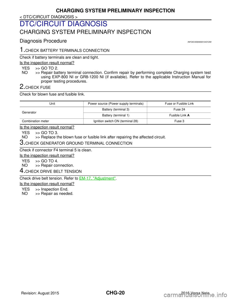
1.CHECK BATTERY TERMINALS CONNECTION
Check if battery terminals are clean and tight.
Is the inspection result normal?
YES >> GO TO 2.
NO >> Repair battery terminal connection. Confirm repair by performing complete Charging system test using EXP-800 NI or GR8-1200 NI (if available). Refer to the applicable Instruction Manual for
proper testing procedures.
2.CHECK FUSE
Check for blown fuse and fusible link.
Is the inspection result normal?
YES >> GO TO 3.
NO >> Replace the blown fuse or fusible link after repairing the affected circuit.
3.CHECK GENERATOR GROUND TERMINAL CONNECTION
Check if connector F4 terminal 5 is clean.
Is the inspection result normal?
YES >> GO TO 4.
NO >> Repair connection.
4.CHECK DRIVE BELT TENSION
Check drive belt tension. Refer to EM-17, "
Adjustment".
Is the inspection result normal?
YES >> Inspection End.
NO >> Repair as needed.
Unit Power source (Power supply terminals) Fuse or Fusible Link
Generator Battery (terminal 3)
Fuse 24
Battery (terminal 1) Fusible Link A
Combination meter Ignition switch ON (terminal 28) Fuse 3
Revision: August 2015 2016 Versa Note
cardiagn.com
Page 624 of 3641

CHG
GENERATORCHG-29
< REMOVAL AND INSTALLATION >
C
DE
F
G H
I
J
K L
B A
O P
N
REMOVAL AND INSTALLATION
GENERATOR
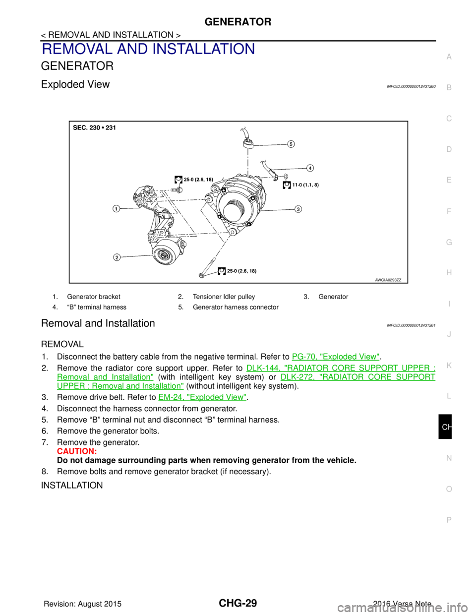
Exploded ViewINFOID:0000000012431260
Removal and InstallationINFOID:0000000012431261
REMOVAL
1. Disconnect the battery cable from
the negative terminal. Refer to PG-70, "Exploded View".
2. Remove the radiator core support upper. Refer to DLK-144, "
RADIATOR CORE SUPPORT UPPER :
Removal and Installation" (with intelligent key system) or DLK-272, "RADIATOR CORE SUPPORT
UPPER : Removal and Installation" (without intelligent key system).
3. Remove drive belt. Refer to EM-24, "
Exploded View".
4. Disconnect the harness connector from generator.
5. Remove “B” terminal nut and disconnect “B” terminal harness.
6. Remove the generator bolts.
7. Remove the generator. CAUTION:
Do not damage surrounding parts when removing generator from the vehicle.
8. Remove bolts and remove generator bracket (if necessary).
INSTALLATION
1. Generator bracket 2. Tensioner Idler pulley3. Generator
4. “B” terminal harness 5. Generator harness connector
AWGIA0293ZZ
Revision: August 2015 2016 Versa Note
cardiagn.com
Page 627 of 3641

CL-1
TRANSMISSION & DRIVELINE
CEF
G H
I
J
K L
M
SECTION CL
A
B
CL
N
O P
CONTENTS
CLUTCH
PRECAUTION ....... ........................................2
PRECAUTIONS .............................................. .....2
Precaution for Supplemental Restraint System
(SRS) "AIR BAG" and "SEAT BELT PRE-TEN-
SIONER" ............................................................. ......
2
General Precautions .................................................2
PREPARATION ............................................3
PREPARATION .............................................. .....3
Special Service Tool ........................................... ......3
Commercial Service Tools ........................................3
SYMPTOM DIAGNOSIS ...............................4
NOISE, VIBRATION AND HARSHNESS
(NVH) TROUBLESHOOTING ........................ .....
4
NVH Troubleshooting Chart ................................ ......4
PERIODIC MAINTENANCE ..........................5
CLUTCH PEDAL .................................................5
Inspection and Adjustment .................................. ......5
CLUTCH FLUID ...................................................7
Inspection ............................................................ ......7
Draining .....................................................................7
Refilling .....................................................................8
Air Bleeding ...............................................................9
REMOVAL AND INSTALLATION ...............11
CLUTCH PEDAL ................................................11
Exploded View .................................................... ....11
Removal and Installation .........................................11
Inspection and Adjustment .................................. ....12
CLUTCH MASTER CYLINDER ........................13
Exploded View .........................................................13
Removal and Installation .........................................13
Inspection and Adjustment ......................................14
CLUTCH PIPING ...............................................15
Exploded View .........................................................15
Hydraulic Layout ......................................................15
Removal and Installation .........................................15
Inspection and Adjustment ......................................16
UNIT REMOVAL AND INSTALLATION ......17
CSC (CONCENTRIC SLAVE CYLINDER) .......17
Exploded View ..................................................... ....17
Removal and Installation .........................................17
Inspection and Adjustment ......................................18
CLUTCH DISC AND CLUTCH COVER ............19
Exploded View .........................................................19
Removal and Installation .........................................19
Inspection ................................................................20
SERVICE DATA AND SPECIFICATIONS
(SDS) ............... .......................................... ...
22
SERVICE DATA AND SPECIFICATIONS
(SDS) .................................................................
22
General Specifications ......................................... ....22
Clutch Pedal ............................................................22
Clutch Disc ..............................................................22
Clutch Cover ............................................................22
Revision: August 2015 2016 Versa Note
cardiagn.com