2016 NISSAN NOTE steering
[x] Cancel search: steeringPage 3132 of 3641
SR-16
< REMOVAL AND INSTALLATION >
SPIRAL CABLE
SPIRAL CABLE
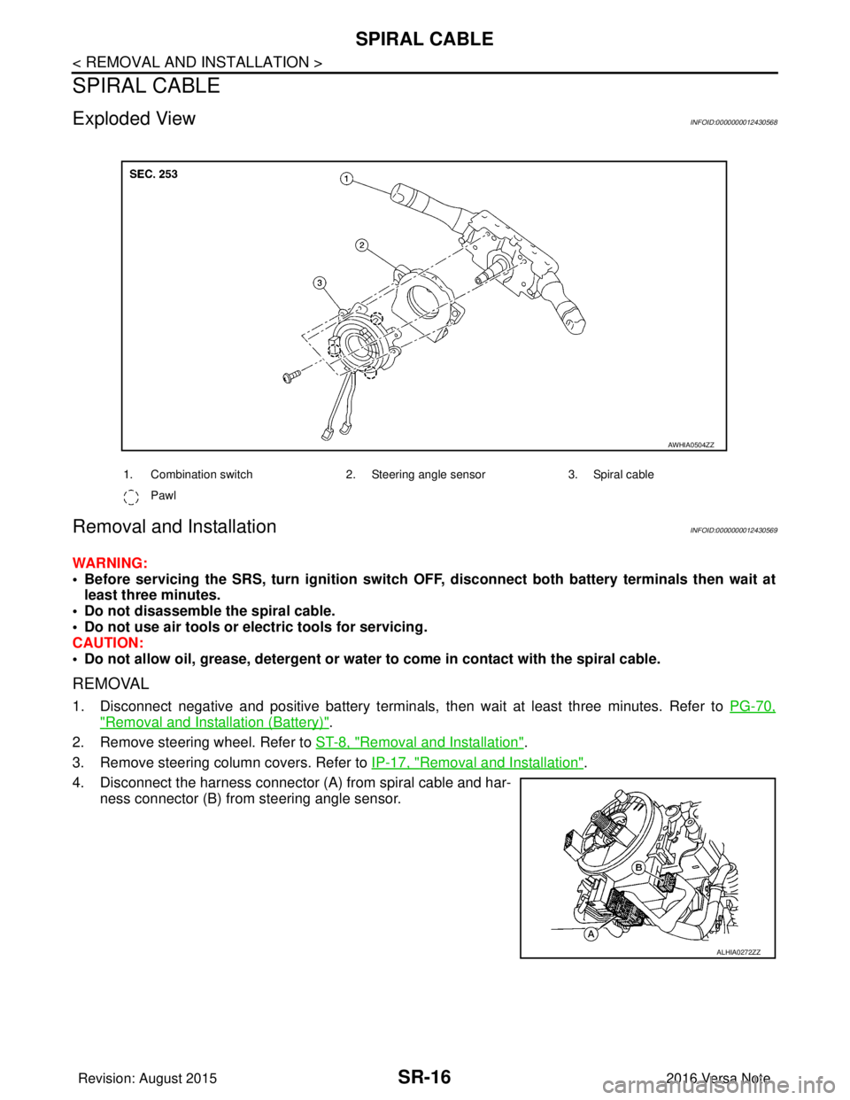
Exploded ViewINFOID:0000000012430568
Removal and InstallationINFOID:0000000012430569
WARNING:
• Before servicing the SRS, turn ignition switch OFF, disconnect bot h battery terminals then wait at
least three minutes.
• Do not disassemble the spiral cable.
• Do not use air tools or el ectric tools for servicing.
CAUTION:
• Do not allow oil, grease, detergent or water to come in contact with the spiral cable.
REMOVAL
1. Disconnect negative and positive battery terminals, then wait at least three minutes. Refer to PG-70,
"Removal and Installation (Battery)".
2. Remove steering wheel. Refer to ST-8, "
Removal and Installation".
3. Remove steering column covers. Refer to IP-17, "
Removal and Installation".
4. Disconnect the harness connector (A) from spiral cable and har- ness connector (B) from steering angle sensor.
1. Combination switch 2. Steering angle sensor3. Spiral cable
Pawl
AWHIA0504ZZ
ALHIA0272ZZ
Revision: August 2015 2016 Versa Note
cardiagn.com
Page 3133 of 3641
SPIRAL CABLESR-17
< REMOVAL AND INSTALLATION >
C
DE
F
G
I
J
K L
M A
B
SR
N
O P
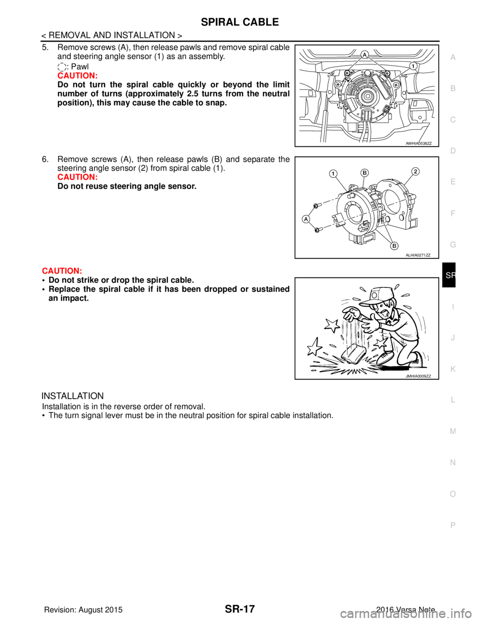
5. Remove screws (A), then release pawls and remove spiral cable and steering angle sensor (1) as an assembly.
: Pawl
CAUTION:
Do not turn the spiral cable quickly or beyond the limit
number of turns (approximately 2.5 turns from the neutral
position), this may cause the cable to snap.
6. Remove screws (A), then release pawls (B) and separate the steering angle sensor (2) from spiral cable (1).
CAUTION:
Do not reuse steering angle sensor.
CAUTION:
• Do not strike or drop the spiral cable.
• Replace the spiral cable if it has been dropped or sustained
an impact.
INSTALLATION
Installation is in the reverse order of removal.
• The turn signal lever must be in the neutral position for spiral cable installation.
AWHIA0538ZZ
ALHIA0271ZZ
JMHIA0009ZZ
Revision: August 2015 2016 Versa Note
cardiagn.com
Page 3134 of 3641
SR-18
< REMOVAL AND INSTALLATION >
SPIRAL CABLE
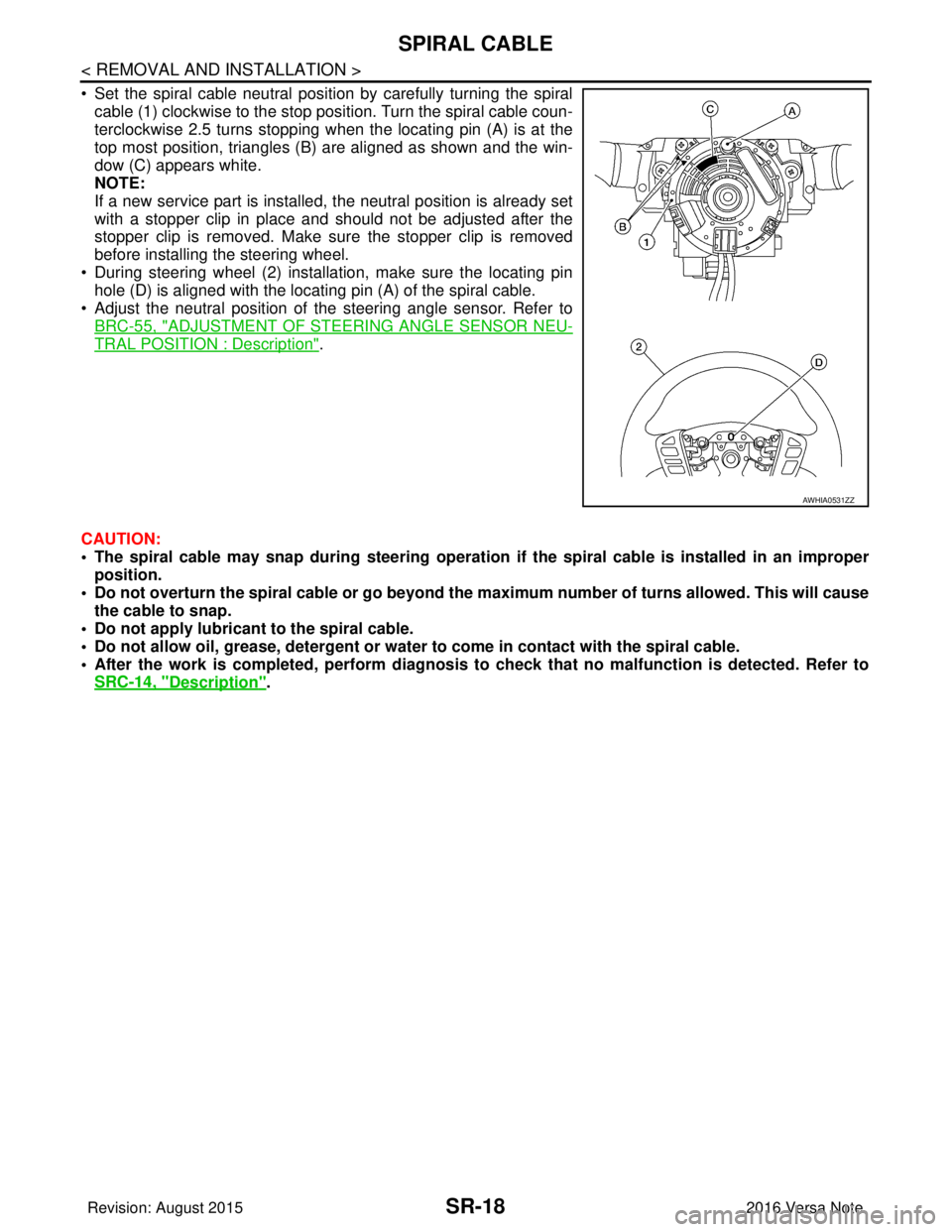
• Set the spiral cable neutral position by carefully turning the spiralcable (1) clockwise to the stop position. Turn the spiral cable coun-
terclockwise 2.5 turns stopping when the locating pin (A) is at the
top most position, triangles (B) are aligned as shown and the win-
dow (C) appears white.
NOTE:
If a new service part is installed, the neutral position is already set
with a stopper clip in place and should not be adjusted after the
stopper clip is removed. Make sure the stopper clip is removed
before installing the steering wheel.
• During steering wheel (2) installation, make sure the locating pin hole (D) is aligned with the locating pin (A) of the spiral cable.
• Adjust the neutral position of the steering angle sensor. Refer to
BRC-55, "
ADJUSTMENT OF STEERI NG ANGLE SENSOR NEU-
TRAL POSITION : Description".
CAUTION:
• The spiral cable may snap during steering operation if the spiral cable is installed in an improper
position.
• Do not overturn the spiral cable or go beyond the maximum number of turns allowed. This will cause
the cable to snap.
• Do not apply lubricant to the spiral cable.
• Do not allow oil, grease, detergent or water to come in contact with the spiral cable.
• After the work is completed, perform diagnosis to check that no malfunction is detected. Refer to
SRC-14, "
Description".
AWHIA0531ZZ
Revision: August 2015 2016 Versa Note
cardiagn.com
Page 3185 of 3641

STC-1
STEERING
C
DE
F
H I
J
K L
M
SECTION STC
A
B
STC
N
O P
CONTENTS
STEERING CONTROL SYSTEM
PRECAUTION ....... ........................................3
PRECAUTIONS .............................................. .....3
Precaution for Supplemental Restraint System
(SRS) "AIR BAG" and "SEAT BELT PRE-TEN-
SIONER" ............................................................. ......
3
Service Notice and Precautions for EPS System ......3
SYSTEM DESCRIPTION ..............................4
COMPONENT PARTS ................................... .....4
Component Parts Location .................................. ......4
EPS Control Unit .......................................................5
EPS Motor, Torque Sensor, Reduction Gear ............5
DIAGNOSIS SYSTEM (EPS CONTROL UNIT)
.....
6
CONSULT Function ............................................ ......6
ECU DIAGNOSIS INFORMATION ...............8
EPS CONTROL UNIT ..................................... .....8
Reference Value ................................................. ......8
Fail-Safe ....................................................................9
Protection Function .................................................10
DTC Inspection Priority Chart ............................. ....10
DTC Index ........................................................... ....10
WIRING DIAGRAM ......................................11
EPS SYSTEM ... .............................................. ....11
Wiring Diagram ................................................... ....11
BASIC INSPECTION ...................................15
DIAGNOSIS AND REPAIR WORKFLOW ..... ....15
Work Flow ........................................................... ....15
Diagnostic Work Sheet ............................................16
DTC/CIRCUIT DIAGNOSIS .........................18
C1601 BATTERY POWER SUPPLY .................18
DTC Logic ........................................................... ....18
Diagnosis Procedure ........................................... ....18
C1604 TORQUE SENSOR ................................21
DTC Logic ................................................................21
Diagnosis Procedure ...............................................21
C1606 EPS MOTOR ..........................................23
DTC Logic ................................................................23
Diagnosis Procedure ...............................................23
Component Inspection .............................................23
C1607, C1608 EPS CONTROL UNIT ...............25
DTC Logic ................................................................25
Diagnosis Procedure ...............................................25
C1609 VEHICLE SPEED SIGNAL ....................26
Description ...............................................................26
DTC Logic ................................................................26
Diagnosis Procedure ...............................................26
C1610 ENGINE STATUS SIGNAL ...................27
Description ...............................................................27
DTC Logic ................................................................27
Diagnosis Procedure ...............................................27
U1000 CAN COMM CIRCUIT ...........................28
Description ...............................................................28
DTC Logic ................................................................28
Diagnosis Procedure ...............................................28
EPS WARNING LAMP ......................................29
Component Function Check ....................................29
Diagnosis Procedure ...............................................29
SYMPTOM DIAGNOSIS ..............................30
EPS WARNING LAMP DOES NOT TURN ON ...30
Description ........................................................... ....30
Diagnosis Procedure ...............................................30
EPS WARNING LAMP DOES NOT TURN
OFF ....................................................................
31
Description ...............................................................31
Revision: August 2015 2016 Versa Note
cardiagn.com
Page 3186 of 3641

STC-2
Diagnosis Procedure ..............................................31
STEERING WHEEL TURNING FORCE IS
HEAVY OR LIGHT .............................................
32
Description ........................................................... ...32
Diagnosis Procedure ..............................................32
UNBALANCE STEERING WHEEL TURNING
FORCE AND RETURN BETWEEN RIGHT
AND LEFT ..........................................................
34
Description ..............................................................34
Diagnosis Procedure ..............................................34
UNBALANCE STEERING WHEEL TURNING
FORCE (TORQUE VARIATION) .......................
35
Description ........................................................... ...35
Diagnosis Procedure ...............................................35
REMOVAL AND INSTALLATION ..............37
EPS CONTROL UNIT ........................................37
Exploded View ..................................................... ...37
Removal and Installation .........................................37
Revision: August 2015 2016 Versa Note
cardiagn.com
Page 3187 of 3641
PRECAUTIONSSTC-3
< PRECAUTION >
C
DE
F
H I
J
K L
M A
B
STC
N
O P
PRECAUTION
PRECAUTIONS
Precaution for Supplemental Restraint System (SRS) "AIR BAG" and "SEAT BELT
PRE-TENSIONER"
INFOID:0000000012431939
The Supplemental Restraint System such as “AIR BAG” and “SEAT BELT PRE-TENSIONER”, used along
with a front seat belt, helps to reduce the risk or severi ty of injury to the driver and front passenger for certain
types of collision. Information necessary to service the system safely is included in the SR and SB section of
this Service Manual.
WARNING:
• To avoid rendering the SRS inoper ative, which could increase the risk of personal injury or death in
the event of a collision which would result in air bag inflation, all maintenance must be performed by
an authorized NISSAN/INFINITI dealer.
• Improper maintenance, including in correct removal and installation of the SRS, can lead to personal
injury caused by unintentional act ivation of the system. For removal of Spiral Cable and Air Bag
Module, see the SR section.
• Do not use electrical test equipm ent on any circuit related to the SRS unless instructed to in this
Service Manual. SRS wiring harnesses can be identi fied by yellow and/or orange harnesses or har-
ness connectors.
PRECAUTIONS WHEN USING POWER TOOLS (AIR OR ELECTRIC) AND HAMMERS
WARNING:
• When working near the Airbag Diagnosis Sensor Un it or other Airbag System sensors with the Igni-
tion ON or engine running, DO NOT use air or el ectric power tools or strike near the sensor(s) with a
hammer. Heavy vibration could activate the sensor( s) and deploy the air bag(s), possibly causing
serious injury.
• When using air or electric power tools or hammers, always switch the Ignition OFF, disconnect the
battery and wait at least three mi nutes before performing any service.
Service Notice and Precautions for EPS SystemINFOID:0000000012431940
• Check the following item when performing the trouble diagnosis:
- Check for possible causes of the malfunction by inte rviewing the customer as to what conditions were
present when the symptom occurred.
- Check if the steering wheel and the EPS control unit are genuine parts.
- Check if the air pressure and size of each tire is correct.
- Check if the installation of the links and suspension components are correct.
- Check if the tires are worn evenly, indicating the wheel alignment is correct.
- Check if the installation of the steering column and t he steering gear are correct. Check for loose bolts, dam-
aged links, cracked boots and leaking grease, etc.
- Check for damage or modification to suspension or body resulting in increased weight or altered ground clearance.
- Check if the battery voltage is proper.
- Check the EPS control unit harness to be sure the harness connectors are fully seated.
• Before connecting or disconnecting the EPS control uni t harness connector, turn ignition switch “OFF” and
disconnect the battery cable from the negative terminal. Battery voltage is applied to the EPS control unit
even if ignition switch is turned “OFF”.
Revision: August 2015 2016 Versa Note
cardiagn.com
Page 3188 of 3641
STC-4
< SYSTEM DESCRIPTION >
COMPONENT PARTS
SYSTEM DESCRIPTION
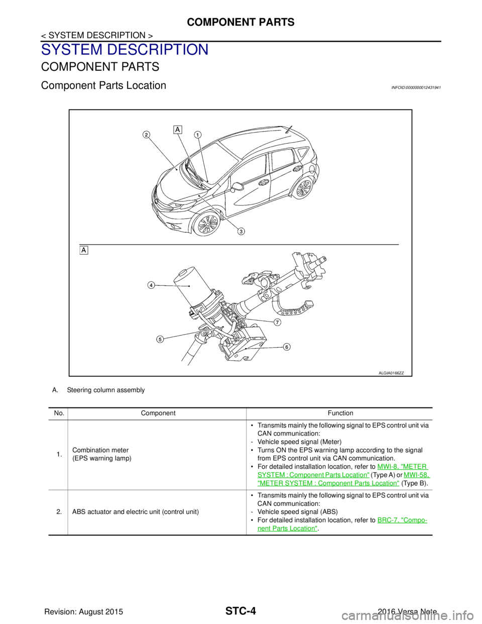
COMPONENT PARTS
Component Parts LocationINFOID:0000000012431941
A. Steering column assemblyNo. Component Function
1. Combination meter
(EPS warning lamp) • Transmits mainly th
e following signal to EPS control unit via
CAN communication:
- Vehicle speed signal (Meter)
• Turns ON the EPS warning lamp according to the signal from EPS control unit via CAN communication.
• For detailed installation location, refer to MWI-8, "
METER
SYSTEM : Component Parts Location" (Type A) or MWI-58,
"METER SYSTEM : Component Parts Location" (Type B).
2. ABS actuator and electric unit (control unit) • Transmits mainly th
e following signal to EPS control unit via
CAN communication:
- Vehicle speed signal (ABS)
• For detailed installation location, refer to BRC-7, "
Compo-
nent Parts Location".
ALGIA0166ZZ
Revision: August 2015 2016 Versa Note
cardiagn.com
Page 3189 of 3641
COMPONENT PARTSSTC-5
< SYSTEM DESCRIPTION >
C
DE
F
H I
J
K L
M A
B
STC
N
O P
EPS Control UnitINFOID:0000000012431942
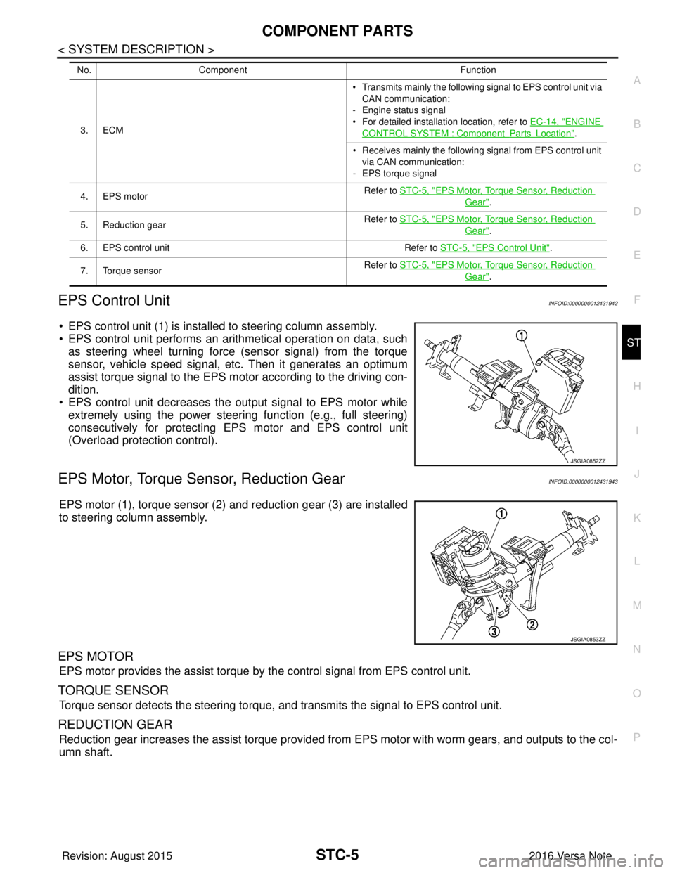
• EPS control unit (1) is installed to steering column assembly.
• EPS control unit performs an arithmetical operation on data, such as steering wheel turning force (sensor signal) from the torque
sensor, vehicle speed signal, etc. Then it generates an optimum
assist torque signal to the EPS motor according to the driving con-
dition.
• EPS control unit decreases the output signal to EPS motor while
extremely using the power steering function (e.g., full steering)
consecutively for protecting EPS motor and EPS control unit
(Overload protection control).
EPS Motor, Torque Sensor, Reduction GearINFOID:0000000012431943
EPS motor (1), torque sensor (2) and reduction gear (3) are installed
to steering column assembly.
EPS MOTOR
EPS motor provides the assist torque by the control signal from EPS control unit.
TORQUE SENSOR
Torque sensor detects the steering torque, and transmits the signal to EPS control unit.
REDUCTION GEAR
Reduction gear increases the assist torque provided from EPS motor with worm gears, and outputs to the col-
umn shaft.
3. ECM • Transmits mainly th
e following signal to EPS control unit via
CAN communication:
- Engine status signal
• For detailed installation location, refer to EC-14, "ENGINE
CONTROL SYSTEM : ComponentPartsLocation".
• Receives mainly the following signal from EPS control unit
via CAN communication:
- EPS torque signal
4. EPS motor Refer to STC-5, "
EPS Motor, Torque Sensor, Reduction
Gear".
5. Reduction gear Refer to STC-5, "
EPS Motor, Torque Sensor, Reduction
Gear".
6. EPS control unit Refer to STC-5, "
EPS Control Unit".
7. Torque sensor Refer to STC-5, "
EPS Motor, Torque Sensor, Reduction
Gear".
No.
Component Function
JSGIA0852ZZ
JSGIA0853ZZ
Revision: August 2015 2016 Versa Note
cardiagn.com