2016 NISSAN NOTE steering
[x] Cancel search: steeringPage 2734 of 3641

RSU-6
< PERIODIC MAINTENANCE >
WHEEL ALIGNMENT
WHEEL ALIGNMENT
InspectionINFOID:0000000012431922
DESCRIPTION
Measure the wheel alignment under unladen conditions.
NOTE:
“Unladen conditions” means that fuel, engine coolant, and lubricants are full. Spare tire, jack, hand tools and
mats are in designated positions.
PRELIMINARY
Check the following:
1. Tires for improper air pressure and wear.
2. Road wheels for runout. Refer to WT-44, "
Inspection".
3. Wheel bearing axial end play. Refer to RAX-10, "
Wheel Bearing".
4. Shock absorber operation.
5. Each mounting part of suspension for looseness and deformation.
6. Rear suspension beam for cracks, deformation, and other damage.
7. Vehicle height (posture).
GENERAL INFORMATION AND RECOMMENDATIONS
1. A Four-Wheel Thrust Alignment should be performed. • This type of alignment is recommended for any NISSAN/INFINITI vehicle.
• The four-wheel “thrust” process helps ensure that the vehicle is properly aligned and the steering wheel
is centered.
• The alignment machine itself should be capabl e of accepting any NISSAN/INFINITI vehicle.
• The alignment machine should be checked to ensure that it is level.
2. Make sure the alignment machine is properly calibrated. • Your alignment machine should be regularly calibrated in order to give correct information.
• Check with the manufacturer of your specific al ignment machine for their recommended Service/Cali-
bration Schedule.
THE ALIGNMENT PROCESS
IMPORTANT: Use only the alignment specifications listed in this Service Manual. Refer to RSU-15, "Wheel
Alignment (Unladen*1)".
1. When displaying the alignment settings, many alignment machines use “indicators”: (Green/red, plus or minus, Go/No Go). Do NOT use these indicators.
• The alignment specifications programmed into your alignment machine that operate these indicators may not be correct.
• This may result in an ERROR.
2. Most camera-type alignment machines are equipped with both "Rolling Compensation" method and optional "Jacking Compensation" method to "com pensate" the alignment targets or head units.
"Rolling Compensation" is the preferred method.
• If using the "Rolling Compensation" method, after installing the alignment targets or head units, push or pull on the rear wheel to move the vehicle. Do not push or pull the vehicle body.
• If using the "Jacking Compensation" method, after in stalling the alignment targets or head units, raise
the vehicle and rotate the wheels 1/2 turn both ways.
NOTE:
Do not use the "rolling compensation" if you are using sensor-type alignment equipment.
• Follow all instructions for the alignment machine you're using for more information.
CAMBER INSPECTION
• Measure camber of both right and left wheels with a suitable alignment gauge.
• If it is out of the specificati on value, inspect and replace any damaged or worn rear suspension parts.
Camber : Refer to RSU-15, "
Wheel Alignment
(Unladen*1)".
Revision: August 2015
2016 Versa Note
cardiagn.com
Page 2742 of 3641

RSU-14
< REMOVAL AND INSTALLATION >
REAR SUSPENSION BEAM
• Perform the final tightening of the rear suspension beam nuts and bolts under unladen conditions with thetires on level ground.
• Adjust the parking brake. Refer to PB-4, "
Inspection and Adjustment".
• Fill the hydraulic brake system. Refer to BR-12, "
Refilling".
• Bleed the hydraulic brake system. Refer to BR-13, "
Bleeding Brake System".
• Complete the inspection. Refer to BR-12, "
Inspection".
InspectionINFOID:0000000012431932
INSPECTION AFTER REMOVAL
Check the rear suspension beam for deformation, cracks or damage. Replace the parts if necessary.
INSPECTION AFTER INSTALLATION
1. Check the wheel sensor harness to be sure the connectors are fully seated.
2. Check the neutral position of the steering angle sensor. Refer to BRC-55, "
ADJUSTMENT OF STEERING
ANGLE SENSOR NEUTRAL POSITION : Description".
3. Check the wheel alignment. Refer to RSU-6, "
Inspection".
Revision: August 2015 2016 Versa Note
cardiagn.com
Page 2786 of 3641

NOISE, VIBRATION AND HARSHNESS (NVH) TROUBLESHOOTINGWT-43
< SYMPTOM DIAGNOSIS >
C
DF
G H
I
J
K L
M A
B
WT
N
O P
NOISE, VIBRATION AND HARSHN ESS (NVH) TROUBLESHOOTING
NVH Troubleshooting ChartINFOID:0000000012432464
Use chart below to find the cause of the symptom . If necessary, repair or replace these parts.
×: Applicable
Reference page
WT-44WT-44WT-45WT-54FSU-8—
—
WT-54FSU-5FA X - 6RAX-4RSU-4—
—
FA X - 6BR-7ST-7
Possible cause and SUSPECTED PARTS
Improper installation, looseness
Out-of-round
Imbalance
Incorrect tire pressure
Uneven tire wear
Deformation or damage
Non-uniformity
Incorrect tire size
FRONT AXLE AND FRONT SUSPENSION
REAR AXLE AND REAR SUSPENSION
TIRES
ROAD WHEELS
DRIVE SHAFT
BRAKE
STEERING
Symptom TIRENoise
××××××× × × ××××
Shake ×××××× × × × ××××
Vibration ××××××
Shimmy ×××××××× × × × ××
Shudder ×
××××× × × × × ××
Poor quality ride or
handling ×××××× × × ××
WHEEL Noise
××× × × × × ×××
Shake ××× × × × × ×××
Shimmy, Shudder ×××× ×××××
Poor quality ride or
handling ×× × ×
× × ×
Revision: August 2015 2016 Versa Note
cardiagn.com
Page 2864 of 3641
![NISSAN NOTE 2016 Service Repair Manual COMPONENT PARTSSEC-7
< SYSTEM DESCRIPTION > [WITH INTELLIGENT KEY SYSTEM]
C
D
E
F
G H
I
J
L
M A
B
SEC
N
O P
SYSTEM DESCRIPTION
COMPONENT PARTS
Component Parts LocationINFOID:0000000012430324
A. View r NISSAN NOTE 2016 Service Repair Manual COMPONENT PARTSSEC-7
< SYSTEM DESCRIPTION > [WITH INTELLIGENT KEY SYSTEM]
C
D
E
F
G H
I
J
L
M A
B
SEC
N
O P
SYSTEM DESCRIPTION
COMPONENT PARTS
Component Parts LocationINFOID:0000000012430324
A. View r](/manual-img/5/57363/w960_57363-2863.png)
COMPONENT PARTSSEC-7
< SYSTEM DESCRIPTION > [WITH INTELLIGENT KEY SYSTEM]
C
D
E
F
G H
I
J
L
M A
B
SEC
N
O P
SYSTEM DESCRIPTION
COMPONENT PARTS
Component Parts LocationINFOID:0000000012430324
A. View right of steering column B. View with glove box cover removed No. Component Function
1. Combination meter Combination meter transmits the vehicle
speed signal to BCM via CAN communica-
tion.
BCM also receives the vehicle speed signal
from ABS actuator and electric unit (control
unit) via CAN communication. BCM com-
pares both signals to detect the vehicle
speed.
Security indicator lamp is located on combi-
nation meter.
Security indicator lamp blinks when ignition
switch is in any position other than ON to
warn that NISSAN VEHICLE IMMOBILIZER
SYSTEM-NATS [NVIS (NATS)] is on board.
Refer to MWI-9, "
METER SYSTEM : Combi-
nation Meter".
2. Inside key antenna (instrument center) Inside key antenna (instrument center) de-
tects whether Intelligent Key is inside the ve-
hicle or not, and then transmits the signal to
the BCM.
Refer to SEC-10, "
Inside Key Antenna".
AWKIA3649ZZ
Revision: August 2015
2016 Versa Note
cardiagn.com
Page 2976 of 3641
![NISSAN NOTE 2016 Service Repair Manual COMPONENT PARTSSEC-119
< SYSTEM DESCRIPTION > [WITHOUT INTELLIGENT KEY SYSTEM]
C
D
E
F
G H
I
J
L
M A
B
SEC
N
O P
SYSTEM DESCRIPTION
COMPONENT PARTS
NISSAN VEHICLE IMMOBILIZER SYSTEM-NATS
NISSAN VEHICL NISSAN NOTE 2016 Service Repair Manual COMPONENT PARTSSEC-119
< SYSTEM DESCRIPTION > [WITHOUT INTELLIGENT KEY SYSTEM]
C
D
E
F
G H
I
J
L
M A
B
SEC
N
O P
SYSTEM DESCRIPTION
COMPONENT PARTS
NISSAN VEHICLE IMMOBILIZER SYSTEM-NATS
NISSAN VEHICL](/manual-img/5/57363/w960_57363-2975.png)
COMPONENT PARTSSEC-119
< SYSTEM DESCRIPTION > [WITHOUT INTELLIGENT KEY SYSTEM]
C
D
E
F
G H
I
J
L
M A
B
SEC
N
O P
SYSTEM DESCRIPTION
COMPONENT PARTS
NISSAN VEHICLE IMMOBILIZER SYSTEM-NATS
NISSAN VEHICLE IMMOBILIZER SYSTEM -NATS : Component Parts Location
INFOID:0000000012430442
A. View from right side of steering column B. View with glove box door removed
AWKIA3650ZZ
Revision: August 2015 2016 Versa Note
cardiagn.com
Page 3004 of 3641
![NISSAN NOTE 2016 Service Repair Manual B2191, P1615 DIFFERENCE OF KEYSEC-147
< DTC/CIRCUIT DIAGNOSIS > [WITHOUT INTELLIGENT KEY SYSTEM]
C
D
E
F
G H
I
J
L
M A
B
SEC
N
O P
B2191, P1615 DIFFERENCE OF KEY
DescriptionINFOID:0000000012430471
Per NISSAN NOTE 2016 Service Repair Manual B2191, P1615 DIFFERENCE OF KEYSEC-147
< DTC/CIRCUIT DIAGNOSIS > [WITHOUT INTELLIGENT KEY SYSTEM]
C
D
E
F
G H
I
J
L
M A
B
SEC
N
O P
B2191, P1615 DIFFERENCE OF KEY
DescriptionINFOID:0000000012430471
Per](/manual-img/5/57363/w960_57363-3003.png)
B2191, P1615 DIFFERENCE OF KEYSEC-147
< DTC/CIRCUIT DIAGNOSIS > [WITHOUT INTELLIGENT KEY SYSTEM]
C
D
E
F
G H
I
J
L
M A
B
SEC
N
O P
B2191, P1615 DIFFERENCE OF KEY
DescriptionINFOID:0000000012430471
Performs ID verification through BCM when mechanical key is inserted in the ignition key cylinder.
Prohibits the release of steering lock or start of engine when an unregistered ID of mechanical key is used.
DTC LogicINFOID:0000000012430472
DTC DETECTION LOGIC
DTC CONFIRMATION PROCEDURE
1.PERFORM DTC CONFIRMATION PROCEDURE
1. Insert mechanical key into the key cylinder.
2. Check “Self Diagnostic Result” using CONSULT.
Is DTC detected?
YES >> Refer to SEC-147, "Diagnosis Procedure".
NO >> Inspection End.
Diagnosis ProcedureINFOID:0000000012430473
1.PERFORM INITIALIZATION
Perform initialization with CONSULT. Re-register all mechanical keys.
For initialization and registration of mechanical key. Refer to CONSULT Immobilizer mode and follow the on-
screen instructions.
Can the system be initialized and can the engine be started with re-registered mechanical key?
YES >> Mechanical key was unregistered.
NO >> BCM is malfunctioning. • Replace BCM. Refer to BCS-137, "
Removal and Installation".
• Perform initialization again.
DTC No. Trouble diagnosis
name DTC detecting condition
Possible cause
B2191 DIFFERENCE OF
KEY The ID verification results between BCM and me-
chanical key are NG. The registration is necessary.
Mechanical key
P1615
Revision: August 2015 2016 Versa Note
cardiagn.com
Page 3021 of 3641

SRC-4
< PRECAUTION >
PRECAUTIONS
PRECAUTION
PRECAUTIONS
Precaution for Supplemental Restraint System (SRS) "AIR BAG" and "SEAT BELT
PRE-TENSIONER"
INFOID:0000000012430587
The Supplemental Restraint System such as “A IR BAG” and “SEAT BELT PRE-TENSIONER”, used along
with a front seat belt, helps to reduce the risk or severity of injury to the driver and front passenger for certain
types of collision. Information necessary to service the system safely is included in the SR and SB section of
this Service Manual.
WARNING:
• To avoid rendering the SRS inopera tive, which could increase the risk of personal injury or death in
the event of a collision which would result in air bag inflation, all maintenance must be performed by
an authorized NISSAN/INFINITI dealer.
• Improper maintenance, including in correct removal and installation of the SRS, can lead to personal
injury caused by unintent ional activation of the system. For re moval of Spiral Cable and Air Bag
Module, see the SR section.
• Do not use electrical test equipmen t on any circuit related to the SRS unless instructed to in this
Service Manual. SRS wiring harn esses can be identified by yellow and/or orange harnesses or har-
ness connectors.
PRECAUTIONS WHEN USING POWER TOOLS (AIR OR ELECTRIC) AND HAMMERS
WARNING:
• When working near the Airbag Diagnosis Sensor Unit or other Airbag System sensors with the Igni-
tion ON or engine running, DO NOT use air or electri c power tools or strike near the sensor(s) with a
hammer. Heavy vibration could activate the sensor( s) and deploy the air bag(s), possibly causing
serious injury.
• When using air or electric power tools or hammers , always switch the Ignition OFF, disconnect the
battery and wait at least three minutes before performing any service.
ServiceINFOID:0000000012430588
• Never use electrical test equipment to check SRS circuits unless instructed to in this Service Manual.
• Before servicing the SRS, turn ignition switch OF F, disconnect battery negative terminal and wait 3 minutes
or more.
For approximately 3 minutes after the cables are removed, it is still possible for the air bag and seat belt pre-
tensioner to deploy. Therefore, never work on any SR S connectors or wires until at least 3 minutes have
passed.
• Diagnosis sensor unit must always be installed with their arrow marks “ ⇐” pointing towards the front of the
vehicle for proper operation. Also chec k diagnosis sensor unit for cracks, deformities or rust before installa-
tion and replace as required.
• The spiral cable must be aligned with the neutral position since its rotations are limited. Never turn steering wheel and column after removal of steering gear.
• Handle air bag module carefully. Always place driver and front passenger air bag modules with the pad side facing upward and seat mounted front side air bag module standing with the stud bolt side facing down.
• Conduct self-diagnosis to check entire SRS for proper function after replacing any components.
• After air bag inflates, the front instrument panel assembly should be replaced if damaged.
• Always replace instrument panel pad following front passenger air bag deployment.
• Never solder the harness when making repairs. Check that harness is not pinched and that there is no con-
tact with other components.
• Never allow harness to come in contact with oil, grease, waste oil, or water.
• Never insert foreign materials, such as a screwdriver, into the harness connector. (This is to prevent acci- dental activation caused by static electricity.)
• Always use CONSULT or SRS air bag warning lamp to perform the circuit diagnosis. (Never use an electric tester such as a circuit tester.)
Revision: August 2015 2016 Versa Note
cardiagn.com
Page 3023 of 3641

SRC-6
< SYSTEM DESCRIPTION >
COMPONENT PARTS
Driver Air Bag Module
INFOID:0000000012430590
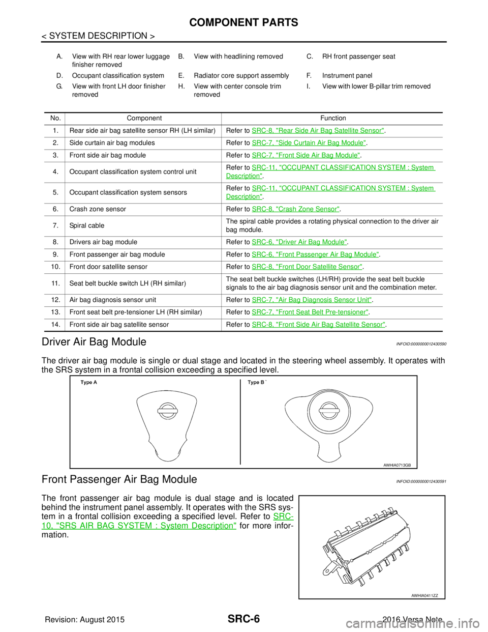
The driver air bag module is single or dual stage and located in the steering wheel assembly. It operates with
the SRS system in a frontal collision exceeding a specified level.
Front Passenger Air Bag ModuleINFOID:0000000012430591
The front passenger air bag module is dual stage and is located
behind the instrument panel assembly. It operates with the SRS sys-
tem in a frontal collision exceeding a specified level. Refer to SRC-
10, "SRS AIR BAG SYSTEM : System Description" for more infor-
mation.
A. View with RH rear lower luggage
finisher removed B. View with headlining removed C. RH front passenger seat
D. Occupant classification system E. Radiator core support assembly F. Instrument panel
G. View with front LH door finisher removed H. View with center console trim
removed I. View with lower B-pillar trim removed
No. Component Function
1. Rear side air bag satellite sensor RH (LH similar) Refer to SRC-8, "
Rear Side Air Bag Satellite Sensor".
2. Side curtain air bag modules Refer to SRC-7, "
Side Curtain Air Bag Module".
3. Front side air bag module Refer to SRC-7, "
Front Side Air Bag Module".
4. Occupant classification system control unit Refer to SRC-11, "
OCCUPANT CLASSIFICATION SYSTEM : System
Description".
5. Occupant classification system sensors Refer to SRC-11, "
OCCUPANT CLASSIFICATION SYSTEM : System
Description".
6. Crash zone sensor Refer to SRC-8, "
Crash Zone Sensor".
7. Spiral cable The spiral cable provides a rotating physical connection to the driver air
bag module.
8. Drivers air bag module Refer to SRC-6, "
Driver Air Bag Module".
9. Front passenger air bag module Refer to SRC-6, "
Front Passenger Air Bag Module".
10. Front door satellite sensor Refer to SRC-8, "
Front Door Satellite Sensor".
11. Seat belt buckle switch LH (RH similar) The seat belt buckle switches (LH/RH) provide the seat belt buckle
signals to the air bag diagnosis sensor unit and the combination meter.
12. Air bag diagnosis sensor unit Refer to SRC-7, "
Air Bag Diagnosis Sensor Unit".
13. Front seat belt pre-tensioner LH (RH similar) Refer to SRC-7, "
Front Seat Belt Pre-tensioner".
14. Front side air bag satellite sensor Refer to SRC-8, "
Front Side Air Bag Satellite Sensor".
AWHIA0713GB
AWHIA0411ZZ
Revision: August 2015 2016 Versa Note
cardiagn.com