2016 NISSAN NOTE key
[x] Cancel search: keyPage 661 of 3641

DEF-10
< SYSTEM DESCRIPTION >
DIAGNOSIS SYSTEM (BCM) (WITHOUT INTELLIGENT KEY SYSTEM)
REAR DEFOGGER
REAR DEFOGGER : CONSULT Function (BCM - REAR DEFOGGER)INFOID:0000000012542310
DATA MONITOR
ACTIVE TEST
Monitor Item [Unit] Description
IGN ON SW [On/Off] Indicates condition of ignition switch ON position.
ACC ON SW [On/Off] Indicates condition of ignition switch ACC position.
REAR DEF SW [On/Off] Indicates condition of rear window defogger switch.
RR DEF TIME [On/Off] Indicates condition of rear window defogger switch timer.
Test Item Description
REAR DEFOGGER This test is able to check rear window defogger operation [Off/On].
Revision: August 2015 2016 Versa Note
cardiagn.com
Page 662 of 3641
BCM
DEF-11
< ECU DIAGNOSIS INFORMATION >
C
D E
F
G H
I
J
K
M A
B
DEF
N
O P
ECU DIAGNOSIS INFORMATION
BCM
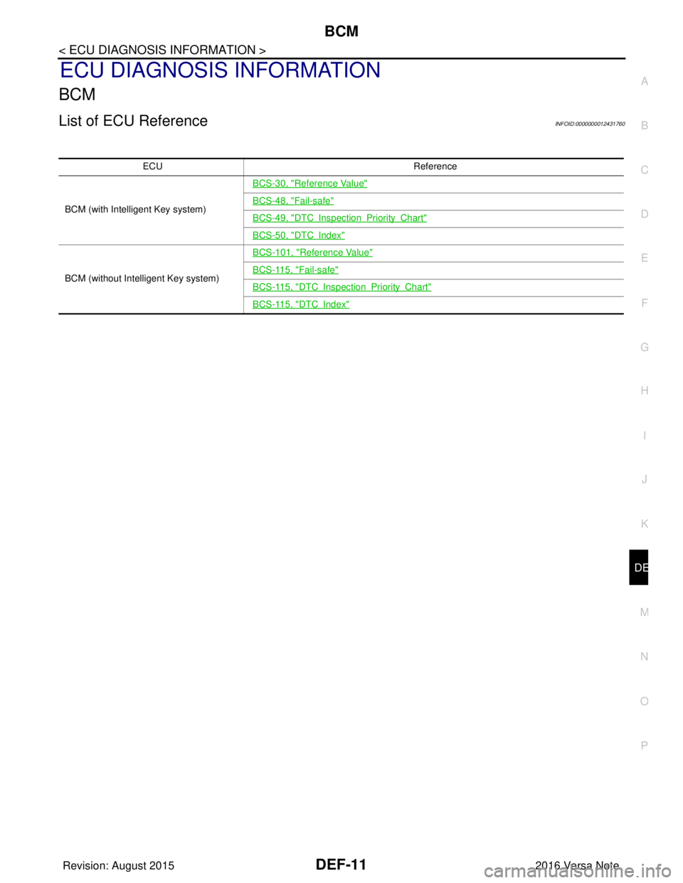
List of ECU ReferenceINFOID:0000000012431760
ECU Reference
BCM (with Intelligent Key system)
BCS-30, "
Reference Value"
BCS-48, "Fail-safe"
BCS-49, "DTCInspectionPriorityChart"
BCS-50, "DTCIndex"
BCM (without Intelligent Key system)
BCS-101, "
Reference Value"
BCS-115, "Fail-safe"
BCS-115, "DTCInspectionPriorityChart"
BCS-115, "DTCIndex"
Revision: August 2015 2016 Versa Note
cardiagn.com
Page 669 of 3641
DEF-18
< BASIC INSPECTION >
DIAGNOSIS AND REPAIR WORK FLOW
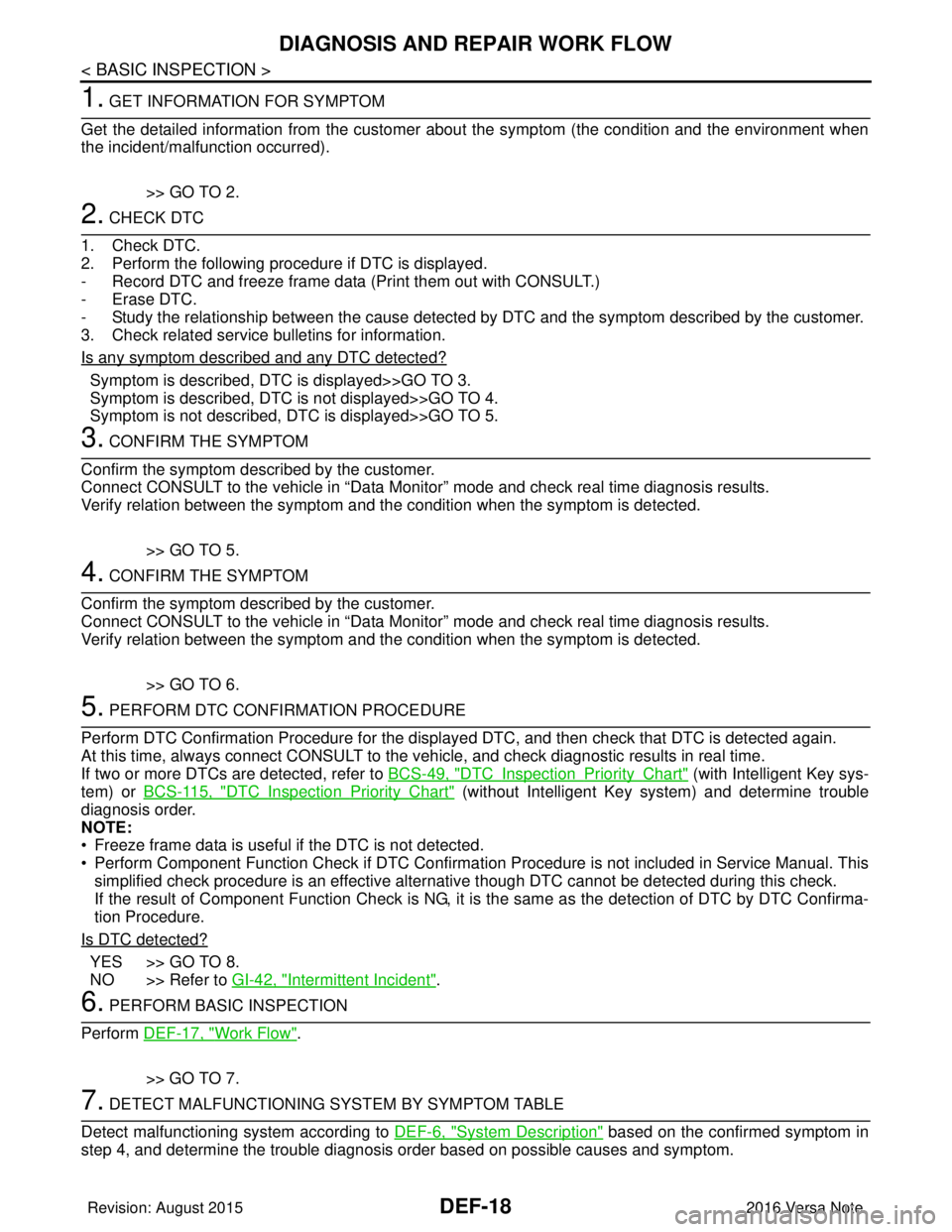
1. GET INFORMATION FOR SYMPTOM
Get the detailed information from the customer about the symptom (the condition and the environment when
the incident/malfunction occurred).
>> GO TO 2.
2. CHECK DTC
1. Check DTC.
2. Perform the following procedure if DTC is displayed.
- Record DTC and freeze frame data (P rint them out with CONSULT.)
- Erase DTC.
- Study the relationship between the cause detected by DTC and the symptom described by the customer.
3. Check related service bulletins for information.
Is any symptom described and any DTC detected?
Symptom is described, DTC is displayed>>GO TO 3.
Symptom is described, DTC is not displayed>>GO TO 4.
Symptom is not described, DTC is displayed>>GO TO 5.
3. CONFIRM THE SYMPTOM
Confirm the symptom described by the customer.
Connect CONSULT to the vehicle in “Data Monitor” mode and check real time diagnosis results.
Verify relation between the symptom and the condition when the symptom is detected.
>> GO TO 5.
4. CONFIRM THE SYMPTOM
Confirm the symptom described by the customer.
Connect CONSULT to the vehicle in “Data Monitor” mode and check real time diagnosis results.
Verify relation between the symptom and the condition when the symptom is detected.
>> GO TO 6.
5. PERFORM DTC CONFIRMATION PROCEDURE
Perform DTC Confirmation Procedure for the display ed DTC, and then check that DTC is detected again.
At this time, always connect CONSULT to the vehicle, and check diagnostic results in real time.
If two or more DTCs are detected, refer to BCS-49, "
DTCInspectionPriorityChart" (with Intelligent Key sys-
tem) or BCS-115, "
DTCInspectionPriorityChart" (without Intelligent Key system) and determine trouble
diagnosis order.
NOTE:
• Freeze frame data is useful if the DTC is not detected.
• Perform Component Function Check if DTC Confirmation Procedure is not included in Service Manual. This simplified check procedure is an effective alternat ive though DTC cannot be detected during this check.
If the result of Component Function Check is NG, it is the same as the detection of DTC by DTC Confirma-
tion Procedure.
Is DTC detected?
YES >> GO TO 8.
NO >> Refer to GI-42, "
Intermittent Incident".
6. PERFORM BASIC INSPECTION
Perform DEF-17, "
Work Flow".
>> GO TO 7.
7. DETECT MALFUNCTIONING SYSTEM BY SYMPTOM TABLE
Detect malfunctioning system according to DEF-6, "
System Description" based on the confirmed symptom in
step 4, and determine the trouble diagnosis order based on possible causes and symptom.
Revision: August 2015 2016 Versa Note
cardiagn.com
Page 672 of 3641
REAR WINDOW DEFOGGER SWITCHDEF-21
< DTC/CIRCUIT DIAGNOSIS >
C
DE
F
G H
I
J
K
M A
B
DEF
N
O P
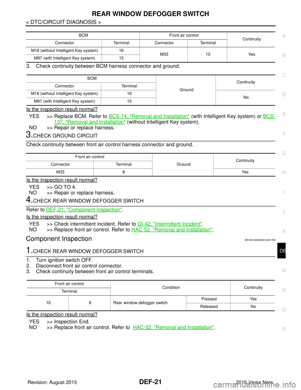
3. Check continuity between BCM harness connector and ground.
Is the inspection result normal?
YES >> Replace BCM. Refer to BCS-74, "Removal and Installation" (with Intelligent Key system) or BCS-
137, "Removal and Installation" (without Intelligent Key system).
NO >> Repair or replace harness.
3.CHECK GROUND CIRCUIT
Check continuity between front air control harness connector and ground.
Is the inspection result normal?
YES >> GO TO 4.
NO >> Repair or replace harness.
4.CHECK REAR WINDOW DEFOGGER SWITCH
Refer to DEF-21, "
Component Inspection".
Is the inspection result normal?
YES >> Check intermittent incident. Refer to GI-42, "Intermittent Incident".
NO >> Replace front air control. Refer to HAC-52, "
Removal and Installation".
Component InspectionINFOID:0000000012431766
1.CHECK REAR WINDOW DEFOGGER SWITCH
1. Turn ignition switch OFF.
2. Disconnect front air control connector.
3. Check continuity between front air control terminals.
Is the inspection result normal?
YES >> Inspection End.
NO >> Replace front air control. Refer to HAC-52, "
Removal and Installation".
BCM Front air control
Continuity
Connector TerminalConnector Terminal
M18 (without Intelligent Key system) 10
M33 10Yes
M97 (with Intelligent Key system) 15
BCM
GroundContinuity
Connector Terminal
M18 (without Intelligent Key system) 10
No
M97 (with Intelligent Key system) 15
Front air control
GroundContinuity
Connector Terminal
M33 8 Yes
Front air control
ConditionContinuity
Te r m i n a l
10 8Rear window defogger switch Pressed
Yes
Released No
Revision: August 2015 2016 Versa Note
cardiagn.com
Page 673 of 3641
DEF-22
< DTC/CIRCUIT DIAGNOSIS >
REAR WINDOW DEFOGGER RELAY
REAR WINDOW DEFOGGER RELAY
DescriptionINFOID:0000000012431767
Power is supplied to the rear window defogger with BCM control.
Component Function CheckINFOID:0000000012431768
1.CHECK FUNCTION
1. Turn ignition switch ON.
2. Check that an operation noise of rear window defogger relay can be heard when turning the rear window defogger switch ON.
Is the inspection result normal?
YES >> Rear window defogger relay function is OK.
NO >> Refer to DEF-22, "
Diagnosis Procedure"
Diagnosis ProcedureINFOID:0000000012431769
Regarding Wiring Diagram information, refer to DEF-12, "Wiring Diagram".
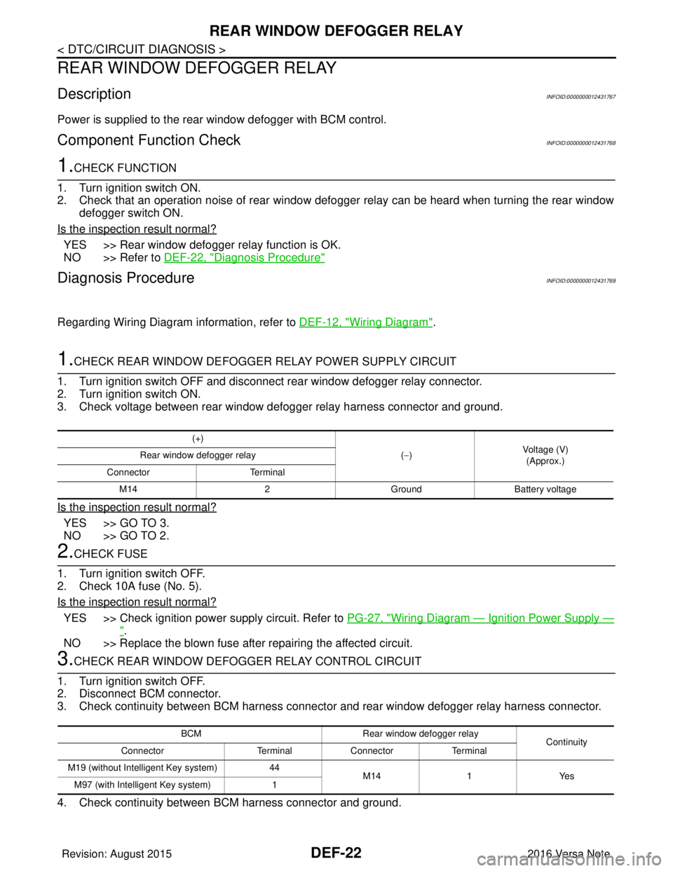
1.CHECK REAR WINDOW DEFOGGER RELAY POWER SUPPLY CIRCUIT
1. Turn ignition switch OFF and disconnect rear window defogger relay connector.
2. Turn ignition switch ON.
3. Check voltage between rear window defogger relay harness connector and ground.
Is the inspection result normal?
YES >> GO TO 3.
NO >> GO TO 2.
2.CHECK FUSE
1. Turn ignition switch OFF.
2. Check 10A fuse (No. 5).
Is the inspection result normal?
YES >> Check ignition power supply circuit. Refer to PG-27, "Wiring Diagram — Ignition Power Supply —
".
NO >> Replace the blown fuse after repairing the affected circuit.
3.CHECK REAR WINDOW DEFOGGER RELAY CONTROL CIRCUIT
1. Turn ignition switch OFF.
2. Disconnect BCM connector.
3. Check continuity between BCM harness connector and rear window defogger relay harness connector.
4. Check continuity between BCM harness connector and ground.
(+)
(−) Voltage (V)
(Approx.)
Rear window defogger relay
Connector Terminal
M14 2GroundBattery voltage
BCM Rear window defogger relay
Continuity
Connector TerminalConnector Terminal
M19 (without Intelligent Key system) 44
M14 1Yes
M97 (with Intelligent Key system) 1
Revision: August 2015 2016 Versa Note
cardiagn.com
Page 674 of 3641
REAR WINDOW DEFOGGER RELAYDEF-23
< DTC/CIRCUIT DIAGNOSIS >
C
DE
F
G H
I
J
K
M A
B
DEF
N
O P
Is the inspection result normal?
YES >> GO TO 4.
NO >> Repair or replace harness.
4.CHECK REAR WINDOW DEFOGGER RELAY
Refer to DEF-23, "
Component Inspection".
Is the inspection result normal?
YES >> Replace BCM. Refer to BCS-74, "Removal and Installation" (with Intelligent Key system) or BCS-
137, "Removal and Installation" (without Intelligent Key system).
NO >> Replace rear window defogger relay.
Component InspectionINFOID:0000000012431770
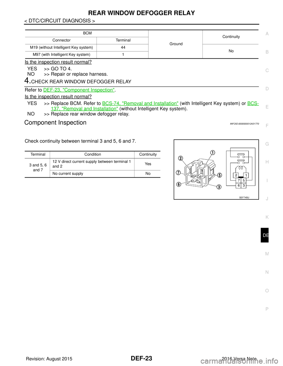
Check continuity between terminal 3 and 5, 6 and 7.
BCM
GroundContinuity
Connector Terminal
M19 (without Intelligent Key system) 44
No
M97 (with Intelligent Key system) 1
TerminalCondition Continuity
3 and 5, 6 and 7 12 V direct current supply between terminal 1
and 2
Ye s
No current supply No
SEF745U
Revision: August 2015 2016 Versa Note
cardiagn.com
Page 690 of 3641
DLK-1
BODY EXTERIOR, DOORS, ROOF & VEHICLE SECURITY
C
DE
F
G H
I
J
L
M
SECTION DLK
A
B
DLK
N
O P
CONTENTS
DOOR & LOCK
WITH INTELLIGENT KEY SYSTEM
PRECAUTION ....... ........................................
9
PRECAUTIONS .............................................. .....9
Precaution for Supplemental Restraint System
(SRS) "AIR BAG" and "SEAT BELT PRE-TEN-
SIONER" ............................................................. ......
9
Procedure without Cowl Top Cover .......................9
Precaution for Servicing Doors and Locks .......... ......9
Precaution for Work ............................................ ....10
PREPARATION ...........................................11
PREPARATION .............................................. ....11
Special Service Tools .......................................... ....11
Commercial Service Tools ......................................12
SYSTEM DESCRIPTION .............................13
COMPONENT PARTS ................................... ....13
INTELLIGENT KEY SYSTEM ...................................13
INTELLIGENT KEY SYSTEM : Component Parts
Location ............................................................... ....
13
INTELLIGENT KEY SYSTEM : Inside Key Anten-
na (Instrument Center) ............................................
15
INTELLIGENT KEY SYSTEM : Inside Key Anten-
na (Console) ............................................................
16
INTELLIGENT KEY SYSTEM : Inside Key Anten-
na (Trunk Room) .....................................................
16
INTELLIGENT KEY SYSTEM : Outside Key An-
tenna (Rear Bumper) ..............................................
16
INTELLIGENT KEY SYSTEM : Outside Key An-
tenna (Driver Side) ..................................................
16
INTELLIGENT KEY SYSTEM : Outside Key An-
tenna (Passenger Side) ..........................................
17
INTELLIGENT KEY SYSTEM : Front Door Lock
Assembly (Driver Side) ...........................................
17
INTELLIGENT KEY SYSTEM : Remote Keyless
Entry Receiver .........................................................
17
INTELLIGENT KEY SYSTEM : Intelligent Key
Warning Buzzer ................................................... ....
17
INTELLIGENT KEY SYSTEM : Back Door Lock
Assembly .................................................................
18
INTELLIGENT KEY SYSTEM : Door Lock and Un-
lock Switch ........................................................... ....
18
INTELLIGENT KEY SYSTEM : Front Door Re-
quest Switch (Driver Side) .......................................
18
INTELLIGENT KEY SYSTEM : Front Door Re-
quest Switch (Passenger Side) ...............................
18
INTELLIGENT KEY SYSTEM : Door Switch ...........19
INTELLIGENT KEY SYSTEM : Back Door Re-
quest Switch ............................................................
19
SYSTEM (POWER DOOR LOCK SYSTEM) ....20
System Diagram .................................................. ....20
System Description ..................................................20
SYSTEM (INTELLIGENT KEY SYSTEM) .........22
INTELLIGENT KEY SYSTEM ......................... ...........22
INTELLIGENT KEY SYSTEM : System Descrip-
tion ....................................................................... ....
22
DOOR LOCK FUNCTION ...................................... ....23
DOOR LOCK FUNCTION : System Description .....23
REMOTE KEYLESS ENTRY FUNCTION ..................25
REMOTE KEYLESS ENTRY FUNCTION : Sys-
tem Description .................................................... ....
25
KEY REMINDER FUNCTION ................................ ....26
KEY REMINDER FUNCTION : System Descrip-
tion ...........................................................................
27
WARNING FUNCTION .......................................... ....27
WARNING FUNCTION : System Description ..........27
DIAGNOSIS SYSTEM (BCM) ...........................30
COMMON ITEM ..................................................... ....30
COMMON ITEM : CONSULT Function (BCM -
COMMON ITEM) .....................................................
30
Revision: August 2015 2016 Versa Note
cardiagn.com
Page 691 of 3641

DLK-2
DOOR LOCK .............................................................31
DOOR LOCK : CONSULT Function (BCM -
DOOR LOCK) .........................................................
31
INTELLIGENT KEY ................................................ ...31
INTELLIGENT KEY : CONSULT Function (BCM -
INTELLIGENT KEY) ...............................................
31
ECU DIAGNOSIS INFORMATION ........... ...35
BCM ................................................................ ...35
List of ECU Reference ......................................... ...35
WIRING DIAGRAM .....................................36
POWER DOOR LOCK SYSTEM .................... ...36
Wiring Diagram .................................................... ...36
INTELLIGENT KEY SYSTEM ............................46
Wiring Diagram .................................................... ...46
BASIC INSPECTION ...................................61
DIAGNOSIS AND REPAIR WORK FLOW ..... ...61
Work Flow ............................................................ ...61
INSPECTION AND ADJUSTMENT ...................64
ADDITIONAL SERVICE WHEN REPLACING
CONTROL UNIT (BCM) ......................................... ...
64
ADDITIONAL SERVICE WHEN REPLACING
CONTROL UNIT (BCM) : Description ................. ...
64
ADDITIONAL SERVICE WHEN REPLACING
CONTROL UNIT (BCM) : Work Procedure ......... ...
64
DTC/CIRCUIT DIAGNOSIS ...................... ...65
B2621 INSIDE ANTENNA .............................. ...65
DTC Logic ............................................................ ...65
Diagnosis Procedure ..............................................65
B2622 INSIDE ANTENNA .................................67
DTC Logic ............................................................ ...67
Diagnosis Procedure ..............................................67
B2623 INSIDE ANTENNA .................................69
DTC Logic ............................................................ ...69
Diagnosis Procedure ..............................................69
B2626 OUTSIDE ANTENNA .............................71
DTC Logic ............................................................ ...71
Diagnosis Procedure ..............................................71
B2627 OUTSIDE ANTENNA .............................73
DTC Logic ............................................................ ...73
Diagnosis Procedure ..............................................73
B2628 OUTSIDE ANTENNA .............................75
DTC Logic ............................................................ ...75
Diagnosis Procedure ..............................................75
POWER SUPPLY AND GROUND CIRCUIT .....77
BCM ........................................................................ ...77
BCM : Diagnosis Procedure ....................................77
COMBINATION METER BUZZER ....................78
Component Function Check ............................... ...78
Diagnosis Procedure ...............................................78
DOOR LOCK ACTUATOR ................................79
DRIVER SIDE ......................................................... ...79
DRIVER SIDE : Component Function Check ........79
DRIVER SIDE : Diagnosis Procedure .....................79
PASSENGER SIDE ...................................................80
PASSENGER SIDE :
Component Function Check ............................... ...
80
PASSENGER SIDE : Diagnosis Procedure ............80
REAR LH ................................................................ ...81
REAR LH : Component Function Check ...............81
REAR LH : Diagnosis Procedure ............................81
REAR RH ................................................................ ...82
REAR RH : Component Function Check ...............82
REAR RH : Diagnosis Procedure ...........................82
BACK DOOR .......................................................... ...83
BACK DOOR : Description .....................................83
BACK DOOR : Component Function Check .........83
BACK DOOR : Diagnosis Procedure ......................84
BACK DOOR LOCK ACTUATOR RELAY .......86
Description ........................................................... ...86
Component Function Check ...................................86
Diagnosis Procedure ...............................................86
Component Inspection ............................................87
DOOR LOCK AND UNLOCK SWITCH .............89
Component Function Check ............................... ...89
Diagnosis Procedure ...............................................89
Component Inspection ............................................90
UNLOCK SENSOR ............................................92
Component Function Check ............................... ...92
Diagnosis Procedure ...............................................92
Component Inspection ............................................93
DOOR REQUEST SWITCH ...............................94
Component Function Check ..................................94
Diagnosis Procedure ...............................................94
Component Inspection ............................................95
BACK DOOR REQUEST SWITCH ...................96
Description ........................................................... ...96
Component Function Check ..................................96
Diagnosis Procedure ...............................................96
Component Inspection ............................................97
DOOR SWITCH .................................................98
Component Function Check ............................... ...98
Diagnosis Procedure ...............................................98
Component Inspection ............................................99
Revision: August 2015 2016 Versa Note
cardiagn.com