2016 NISSAN NOTE ECU
[x] Cancel search: ECUPage 658 of 3641
DIAGNOSIS SYSTEM (BCM) (WITH INTELLIGENT KEY SYSTEM)
DEF-7
< SYSTEM DESCRIPTION >
C
D E
F
G H
I
J
K
M A
B
DEF
N
O P
DIAGNOSIS SYSTEM (BCM) (WIT H INTELLIGENT KEY SYSTEM)
COMMON ITEM
COMMON ITEM : CONSULT Function (BCM - COMMON ITEM)INFOID:0000000012542306
APPLICATION ITEM
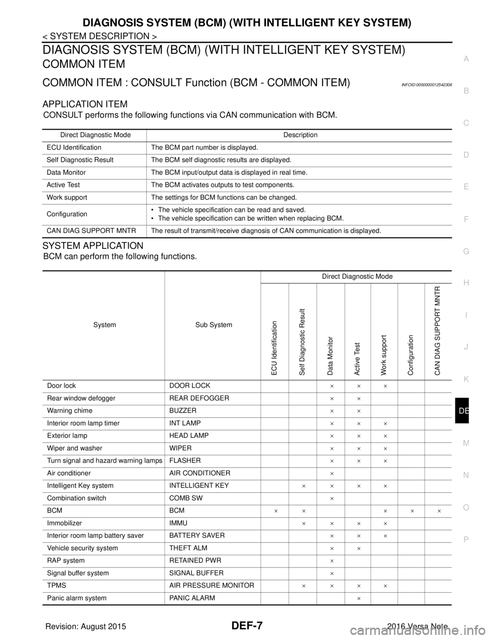
CONSULT performs the following functions via CAN communication with BCM.
SYSTEM APPLICATION
BCM can perform the following functions.
Direct Diagnostic Mode Description
ECU Identification The BCM part number is displayed.
Self Diagnostic Result The BCM self diagnostic results are displayed.
Data Monitor The BCM input/output data is displayed in real time.
Active Test The BCM activates outputs to test components.
Work support The settings for BCM functions can be changed.
Configuration • The vehicle specification can be read and saved.
• The vehicle specification can be written when replacing BCM.
CAN DIAG SUPPORT MNTR The result of transmit/receive diagnosis of CAN communication is displayed.
System Sub System Direct Diagnostic Mode
ECU Identification
Self Diagnostic Result
Data Monitor
Active Test
Work support
Configuration
CAN DIAG SUPPORT MNTR
Door lock
DOOR LOCK ×××
Rear window defogger REAR DEFOGGER ××
Warning chime BUZZER ××
Interior room lamp timer INT LAMP ×××
Exterior lamp HEAD LAMP ×××
Wiper and washer WIPER ×××
Turn signal and hazard warning lamps FLASHER ×××
Air conditioner AIR CONDITIONER ×
Intelligent Key system INTELLIGENT KEY ××××
Combination switch COMB SW ×
BCM BCM× × ×××
Immobilizer IMMU ××××
Interior room lamp battery saver BATTERY SAVER ×××
Vehicle security system THEFT ALM ××
RAP system RETAINED PWR ×
Signal buffer system SIGNAL BUFFER ×
TPMS AIR PRESSURE MONITOR ××××
Panic alarm system PANIC ALARM ×
Revision: August 2015 2016 Versa Note
cardiagn.com
Page 660 of 3641
DIAGNOSIS SYSTEM (BCM) (WITHOUT INTELLIGENT KEY SYSTEM)DEF-9
< SYSTEM DESCRIPTION >
C
DE
F
G H
I
J
K
M A
B
DEF
N
O P
DIAGNOSIS SYSTEM (BCM) (WITHO UT INTELLIGENT KEY SYSTEM)
COMMON ITEM
COMMON ITEM : CONSULT Function (BCM - COMMON ITEM)INFOID:0000000012542309
APPLICATION ITEM
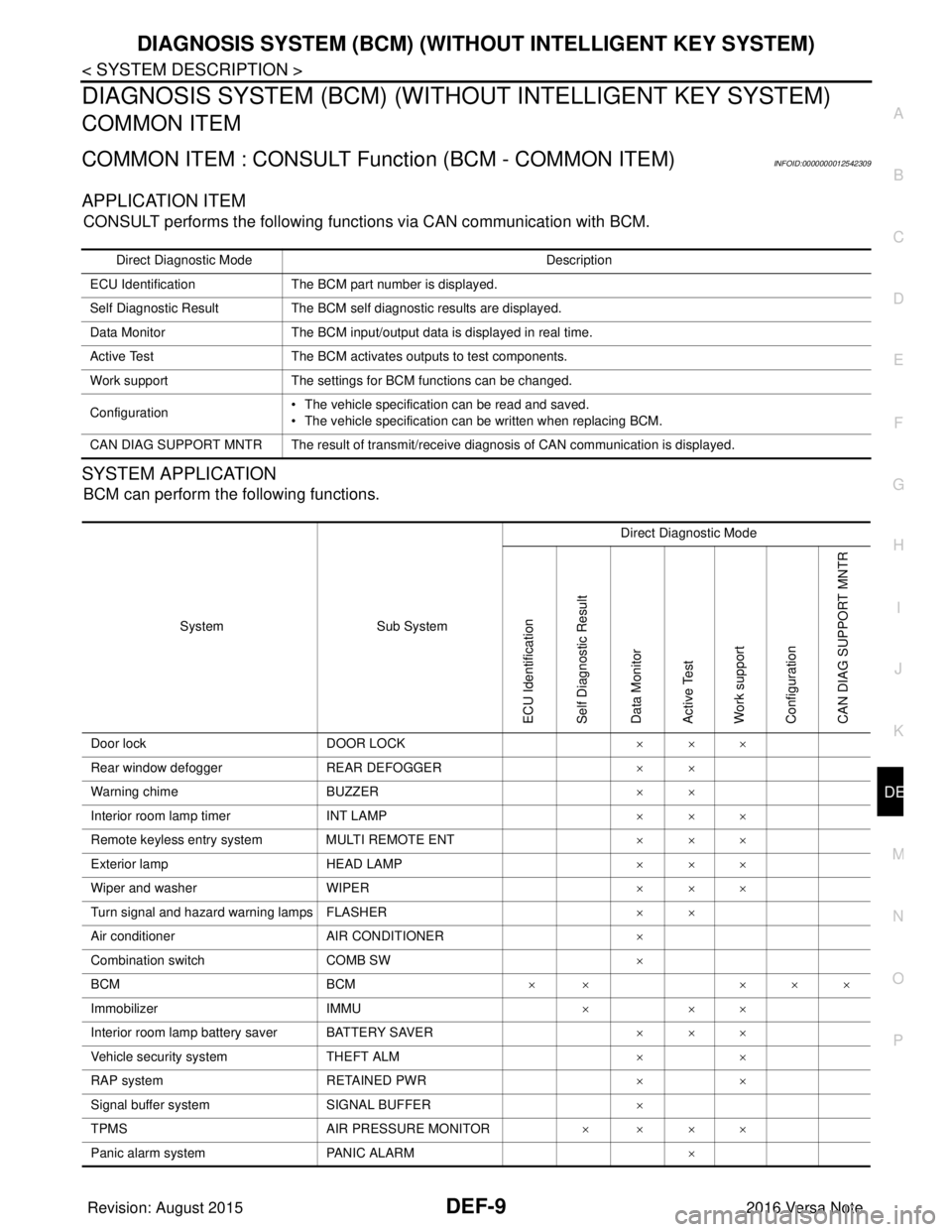
CONSULT performs the following functions via CAN communication with BCM.
SYSTEM APPLICATION
BCM can perform the following functions.
Direct Diagnostic Mode Description
ECU Identification The BCM part number is displayed.
Self Diagnostic Result The BCM self diagnostic results are displayed.
Data Monitor The BCM input/output data is displayed in real time.
Active Test The BCM activates outputs to test components.
Work support The settings for BCM functions can be changed.
Configuration • The vehicle specification can be read and saved.
• The vehicle specification can be written when replacing BCM.
CAN DIAG SUPPORT MNTR The result of transmit/receive diagnosis of CAN communication is displayed.
System Sub System Direct Diagnostic Mode
ECU Identification
Self Diagnostic Result
Data Monitor
Active Test
Work support
Configuration
CAN DIAG SUPPORT MNTR
Door lock
DOOR LOCK ×××
Rear window defogger REAR DEFOGGER ××
Warning chime BUZZER ××
Interior room lamp timer INT LAMP ×××
Remote keyless entry system MULTI REMOTE ENT ×××
Exterior lamp HEAD LAMP ×××
Wiper and washer WIPER ×××
Turn signal and hazard warning lamps FLASHER ××
Air conditioner AIR CONDITIONER ×
Combination switch COMB SW ×
BCM BCM× × ×××
Immobilizer IMMU ×××
Interior room lamp battery saver BATTERY SAVER ×××
Vehicle security system THEFT ALM ××
RAP system RETAINED PWR ××
Signal buffer system SIGNAL BUFFER ×
TPMS AIR PRESSURE MONITOR ××××
Panic alarm system PANIC ALARM ×
Revision: August 2015 2016 Versa Note
cardiagn.com
Page 662 of 3641
BCM
DEF-11
< ECU DIAGNOSIS INFORMATION >
C
D E
F
G H
I
J
K
M A
B
DEF
N
O P
ECU DIAGNOSIS INFORMATION
BCM
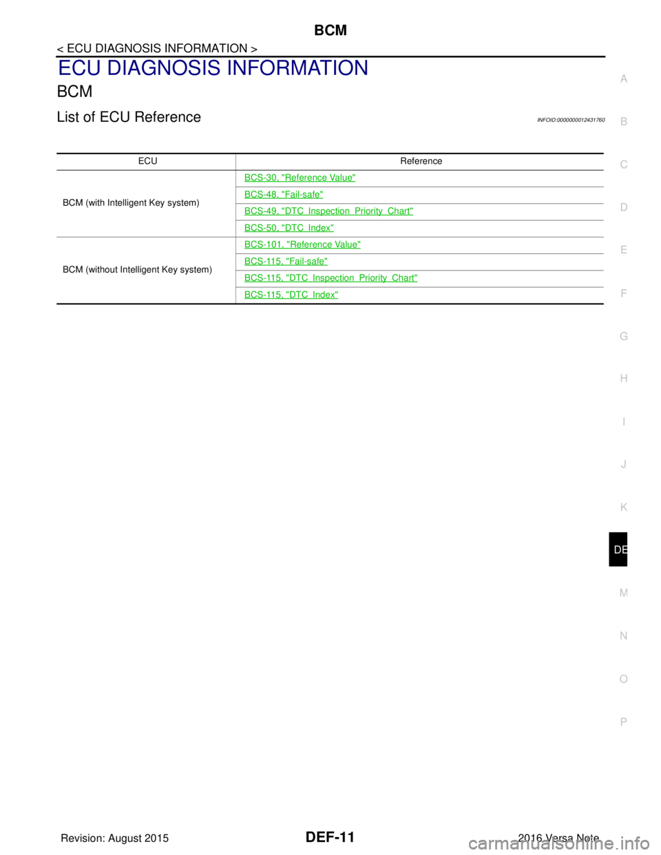
List of ECU ReferenceINFOID:0000000012431760
ECU Reference
BCM (with Intelligent Key system)
BCS-30, "
Reference Value"
BCS-48, "Fail-safe"
BCS-49, "DTCInspectionPriorityChart"
BCS-50, "DTCIndex"
BCM (without Intelligent Key system)
BCS-101, "
Reference Value"
BCS-115, "Fail-safe"
BCS-115, "DTCInspectionPriorityChart"
BCS-115, "DTCIndex"
Revision: August 2015 2016 Versa Note
cardiagn.com
Page 670 of 3641
DIAGNOSIS AND REPAIR WORK FLOWDEF-19
< BASIC INSPECTION >
C
DE
F
G H
I
J
K
M A
B
DEF
N
O P
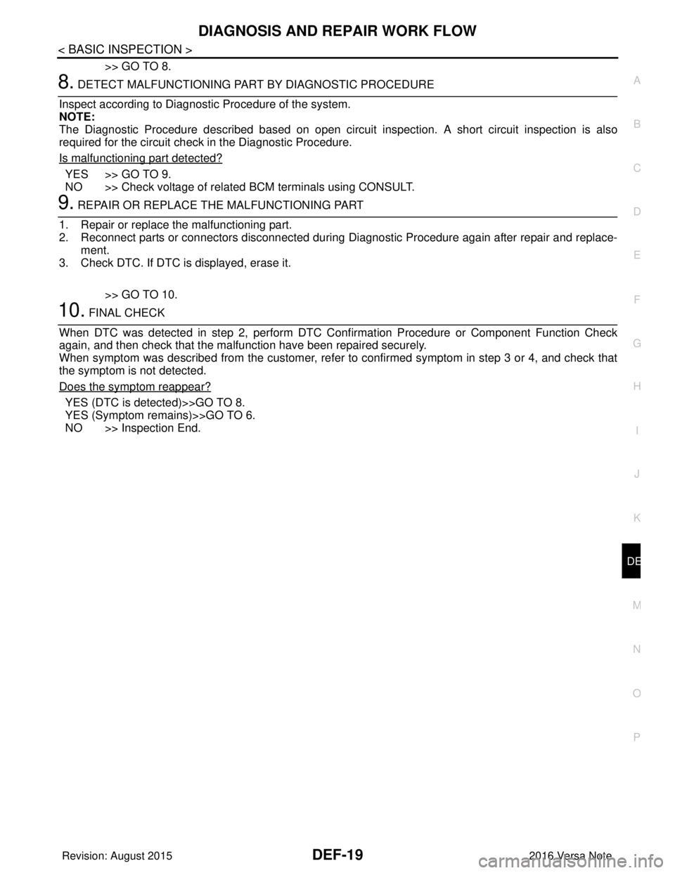
>> GO TO 8.
8. DETECT MALFUNCTIONING PART BY DIAGNOSTIC PROCEDURE
Inspect according to Diagnostic Procedure of the system.
NOTE:
The Diagnostic Procedure described based on open circuit inspection. A short circuit inspection is also
required for the circuit check in the Diagnostic Procedure.
Is malfunctioning part detected?
YES >> GO TO 9.
NO >> Check voltage of related BCM terminals using CONSULT.
9. REPAIR OR REPLACE THE MALFUNCTIONING PART
1. Repair or replace the malfunctioning part.
2. Reconnect parts or connectors disconnected during Diagnostic Procedure again after repair and replace-
ment.
3. Check DTC. If DTC is displayed, erase it.
>> GO TO 10.
10. FINAL CHECK
When DTC was detected in step 2, perform DTC Confirmation Procedure or Component Function Check
again, and then check that the malfunction have been repaired securely.
When symptom was described from the customer, refer to confirmed symptom in step 3 or 4, and check that
the symptom is not detected.
Does the symptom reappear?
YES (DTC is detected)>>GO TO 8.
YES (Symptom remains)>>GO TO 6.
NO >> Inspection End.
Revision: August 2015 2016 Versa Note
cardiagn.com
Page 690 of 3641
DLK-1
BODY EXTERIOR, DOORS, ROOF & VEHICLE SECURITY
C
DE
F
G H
I
J
L
M
SECTION DLK
A
B
DLK
N
O P
CONTENTS
DOOR & LOCK
WITH INTELLIGENT KEY SYSTEM
PRECAUTION ....... ........................................
9
PRECAUTIONS .............................................. .....9
Precaution for Supplemental Restraint System
(SRS) "AIR BAG" and "SEAT BELT PRE-TEN-
SIONER" ............................................................. ......
9
Procedure without Cowl Top Cover .......................9
Precaution for Servicing Doors and Locks .......... ......9
Precaution for Work ............................................ ....10
PREPARATION ...........................................11
PREPARATION .............................................. ....11
Special Service Tools .......................................... ....11
Commercial Service Tools ......................................12
SYSTEM DESCRIPTION .............................13
COMPONENT PARTS ................................... ....13
INTELLIGENT KEY SYSTEM ...................................13
INTELLIGENT KEY SYSTEM : Component Parts
Location ............................................................... ....
13
INTELLIGENT KEY SYSTEM : Inside Key Anten-
na (Instrument Center) ............................................
15
INTELLIGENT KEY SYSTEM : Inside Key Anten-
na (Console) ............................................................
16
INTELLIGENT KEY SYSTEM : Inside Key Anten-
na (Trunk Room) .....................................................
16
INTELLIGENT KEY SYSTEM : Outside Key An-
tenna (Rear Bumper) ..............................................
16
INTELLIGENT KEY SYSTEM : Outside Key An-
tenna (Driver Side) ..................................................
16
INTELLIGENT KEY SYSTEM : Outside Key An-
tenna (Passenger Side) ..........................................
17
INTELLIGENT KEY SYSTEM : Front Door Lock
Assembly (Driver Side) ...........................................
17
INTELLIGENT KEY SYSTEM : Remote Keyless
Entry Receiver .........................................................
17
INTELLIGENT KEY SYSTEM : Intelligent Key
Warning Buzzer ................................................... ....
17
INTELLIGENT KEY SYSTEM : Back Door Lock
Assembly .................................................................
18
INTELLIGENT KEY SYSTEM : Door Lock and Un-
lock Switch ........................................................... ....
18
INTELLIGENT KEY SYSTEM : Front Door Re-
quest Switch (Driver Side) .......................................
18
INTELLIGENT KEY SYSTEM : Front Door Re-
quest Switch (Passenger Side) ...............................
18
INTELLIGENT KEY SYSTEM : Door Switch ...........19
INTELLIGENT KEY SYSTEM : Back Door Re-
quest Switch ............................................................
19
SYSTEM (POWER DOOR LOCK SYSTEM) ....20
System Diagram .................................................. ....20
System Description ..................................................20
SYSTEM (INTELLIGENT KEY SYSTEM) .........22
INTELLIGENT KEY SYSTEM ......................... ...........22
INTELLIGENT KEY SYSTEM : System Descrip-
tion ....................................................................... ....
22
DOOR LOCK FUNCTION ...................................... ....23
DOOR LOCK FUNCTION : System Description .....23
REMOTE KEYLESS ENTRY FUNCTION ..................25
REMOTE KEYLESS ENTRY FUNCTION : Sys-
tem Description .................................................... ....
25
KEY REMINDER FUNCTION ................................ ....26
KEY REMINDER FUNCTION : System Descrip-
tion ...........................................................................
27
WARNING FUNCTION .......................................... ....27
WARNING FUNCTION : System Description ..........27
DIAGNOSIS SYSTEM (BCM) ...........................30
COMMON ITEM ..................................................... ....30
COMMON ITEM : CONSULT Function (BCM -
COMMON ITEM) .....................................................
30
Revision: August 2015 2016 Versa Note
cardiagn.com
Page 691 of 3641

DLK-2
DOOR LOCK .............................................................31
DOOR LOCK : CONSULT Function (BCM -
DOOR LOCK) .........................................................
31
INTELLIGENT KEY ................................................ ...31
INTELLIGENT KEY : CONSULT Function (BCM -
INTELLIGENT KEY) ...............................................
31
ECU DIAGNOSIS INFORMATION ........... ...35
BCM ................................................................ ...35
List of ECU Reference ......................................... ...35
WIRING DIAGRAM .....................................36
POWER DOOR LOCK SYSTEM .................... ...36
Wiring Diagram .................................................... ...36
INTELLIGENT KEY SYSTEM ............................46
Wiring Diagram .................................................... ...46
BASIC INSPECTION ...................................61
DIAGNOSIS AND REPAIR WORK FLOW ..... ...61
Work Flow ............................................................ ...61
INSPECTION AND ADJUSTMENT ...................64
ADDITIONAL SERVICE WHEN REPLACING
CONTROL UNIT (BCM) ......................................... ...
64
ADDITIONAL SERVICE WHEN REPLACING
CONTROL UNIT (BCM) : Description ................. ...
64
ADDITIONAL SERVICE WHEN REPLACING
CONTROL UNIT (BCM) : Work Procedure ......... ...
64
DTC/CIRCUIT DIAGNOSIS ...................... ...65
B2621 INSIDE ANTENNA .............................. ...65
DTC Logic ............................................................ ...65
Diagnosis Procedure ..............................................65
B2622 INSIDE ANTENNA .................................67
DTC Logic ............................................................ ...67
Diagnosis Procedure ..............................................67
B2623 INSIDE ANTENNA .................................69
DTC Logic ............................................................ ...69
Diagnosis Procedure ..............................................69
B2626 OUTSIDE ANTENNA .............................71
DTC Logic ............................................................ ...71
Diagnosis Procedure ..............................................71
B2627 OUTSIDE ANTENNA .............................73
DTC Logic ............................................................ ...73
Diagnosis Procedure ..............................................73
B2628 OUTSIDE ANTENNA .............................75
DTC Logic ............................................................ ...75
Diagnosis Procedure ..............................................75
POWER SUPPLY AND GROUND CIRCUIT .....77
BCM ........................................................................ ...77
BCM : Diagnosis Procedure ....................................77
COMBINATION METER BUZZER ....................78
Component Function Check ............................... ...78
Diagnosis Procedure ...............................................78
DOOR LOCK ACTUATOR ................................79
DRIVER SIDE ......................................................... ...79
DRIVER SIDE : Component Function Check ........79
DRIVER SIDE : Diagnosis Procedure .....................79
PASSENGER SIDE ...................................................80
PASSENGER SIDE :
Component Function Check ............................... ...
80
PASSENGER SIDE : Diagnosis Procedure ............80
REAR LH ................................................................ ...81
REAR LH : Component Function Check ...............81
REAR LH : Diagnosis Procedure ............................81
REAR RH ................................................................ ...82
REAR RH : Component Function Check ...............82
REAR RH : Diagnosis Procedure ...........................82
BACK DOOR .......................................................... ...83
BACK DOOR : Description .....................................83
BACK DOOR : Component Function Check .........83
BACK DOOR : Diagnosis Procedure ......................84
BACK DOOR LOCK ACTUATOR RELAY .......86
Description ........................................................... ...86
Component Function Check ...................................86
Diagnosis Procedure ...............................................86
Component Inspection ............................................87
DOOR LOCK AND UNLOCK SWITCH .............89
Component Function Check ............................... ...89
Diagnosis Procedure ...............................................89
Component Inspection ............................................90
UNLOCK SENSOR ............................................92
Component Function Check ............................... ...92
Diagnosis Procedure ...............................................92
Component Inspection ............................................93
DOOR REQUEST SWITCH ...............................94
Component Function Check ..................................94
Diagnosis Procedure ...............................................94
Component Inspection ............................................95
BACK DOOR REQUEST SWITCH ...................96
Description ........................................................... ...96
Component Function Check ..................................96
Diagnosis Procedure ...............................................96
Component Inspection ............................................97
DOOR SWITCH .................................................98
Component Function Check ............................... ...98
Diagnosis Procedure ...............................................98
Component Inspection ............................................99
Revision: August 2015 2016 Versa Note
cardiagn.com
Page 695 of 3641

DLK-6
REMOTE KEYLESS ENTRY SYSTEM : System
Diagram .................................................................
199
REMOTE KEYLESS ENTRY SYSTEM : System
Description .............................................................
199
DIAGNOSIS SYSTEM (BCM) ..........................201
COMMON ITEM ..................................................... ..201
COMMON ITEM : CONSULT Function (BCM -
COMMON ITEM) ...................................................
201
DOOR LOCK .......................................................... ..202
DOOR LOCK : CONSULT Function (BCM -
DOOR LOCK) ........................................................
202
MULTI REMOTE ENT ............................................ ..202
MULTI REMOTE ENT : CONSULT Function
(BCM - MULTI REMOTE ENT) ..............................
203
ECU DIAGNOSIS INFORMATION .............205
BCM, IPDM E/R .............................................. .205
List of ECU Reference ......................................... ..205
WIRING DIAGRAM ....................................206
POWER DOOR LOCK SYSTEM .................... .206
Wiring Diagram .................................................... ..206
REMOTE KEYLESS ENTRY SYSTEM ...........216
Wiring Diagram .................................................... ..216
BASIC INSPECTION ..................................225
DIAGNOSIS AND REPAIR WORKFLOW ...... .225
Work Flow ............................................................ ..225
INSPECTION AND ADJUSTMENT .................228
ADDITIONAL SERVICE WHEN REPLACING
CONTROL UNIT ..................................................... ..
228
ADDITIONAL SERVICE WHEN REPLACING
CONTROL UNIT : Description ............................. ..
228
ADDITIONAL SERVICE WHEN REPLACING
CONTROL UNIT : Special Repair Requirement ....
228
DTC/CIRCUIT DIAGNOSIS ...................... ..229
U1000 CAN COMM ......................................... .229
Description ........................................................... ..229
DTC Logic ..............................................................229
Diagnosis Procedure .............................................229
U1010 CONTROL UNIT (CAN) .......................230
DTC Logic ............................................................ ..230
Diagnosis Procedure .............................................230
POWER SUPPLY AND GROUND CIRCUIT ...231
BCM ........................................................................ ..231
BCM : Diagnosis Procedure ..................................231
DOOR SWITCH ...............................................232
Description ........................................................... ..232
Component Function Check ............................... .232
Diagnosis Procedure .............................................232
Component Inspection ..........................................234
DOOR LOCK AND UNLOCK SWITCH ............235
DRIVER SIDE ......................................................... .235
DRIVER SIDE : Description ..................................235
DRIVER SIDE : Component Function Check ......235
DRIVER SIDE : Diagnosis Procedure ...................235
PASSENGER SIDE .................................................236
PASSENGER SIDE : Descripti on .........................236
PASSENGER SIDE :
Component Function Check ............................... .
236
PASSENGER SIDE : Diagnosis Procedure ..........237
KEY CYLINDER SWITCH ................................239
Description ........................................................... .239
Component Function Check .................................239
Diagnosis Procedure .............................................239
Component Inspection ..........................................240
KEY SWITCH (BCM INPUT) ............................241
Diagnosis Procedure ............................................ .241
DOOR LOCK ACTUATOR ...............................242
DRIVER SIDE ......................................................... .242
DRIVER SIDE : Description ..................................242
DRIVER SIDE : Component Function Check ......242
DRIVER SIDE : Diagnosis Procedure ...................242
PASSENGER SIDE .................................................243
PASSENGER SIDE : Descripti on .........................243
PASSENGER SIDE :
Component Function Check ............................... .
243
PASSENGER SIDE : Diagnosis Procedure ..........243
REAR LH ................................................................ .244
REAR LH : Description .........................................244
REAR LH : Component Function Check ............ .244
REAR LH : Diagnosis Procedure ..........................244
REAR RH ................................................................ .245
REAR RH : Description .........................................245
REAR RH : Component Function Check .............245
REAR RH : Diagnosis Procedure .........................246
REMOTE KEYLESS ENTRY RECEIVER ........247
Description ........................................................... .247
Component Function Check ................................247
Diagnosis Procedure .............................................247
KEYFOB BATTERY AND FUNCTION .............250
Description ........................................................... .250
Component Function Check ................................250
Diagnosis Procedure .............................................250
HORN FUNCTION ............................................252
Description ........................................................... .252
Component Function Check ................................252
Revision: August 2015 2016 Versa Note
cardiagn.com
Page 699 of 3641
![NISSAN NOTE 2016 Service Repair Manual DLK-10
< PRECAUTION >[WITH INTELLIGENT KEY SYSTEM]
PRECAUTIONS
• Be sure to tighten bolts and nuts securely to the specified torque.
• After installation is complete, be sure
to check that each p NISSAN NOTE 2016 Service Repair Manual DLK-10
< PRECAUTION >[WITH INTELLIGENT KEY SYSTEM]
PRECAUTIONS
• Be sure to tighten bolts and nuts securely to the specified torque.
• After installation is complete, be sure
to check that each p](/manual-img/5/57363/w960_57363-698.png)
DLK-10
< PRECAUTION >[WITH INTELLIGENT KEY SYSTEM]
PRECAUTIONS
• Be sure to tighten bolts and nuts securely to the specified torque.
• After installation is complete, be sure
to check that each part works properly.
• Follow the steps below to clean components:
- Water soluble dirt:
• Dip a soft cloth into lukewarm water, wring the water out of the cloth and wipe the dirty area.
• Then rub with a soft, dry cloth.
- Oily dirt:
• Dip a soft cloth into lukewarm water with mild detergent (concentration: within 2 to 3%) and wipe the dirty area.
• Then dip a cloth into fresh water, wring the water out of the cloth and wipe the detergent off.
• Then rub with a soft, dry cloth.
- Do not use organic solvent such as thinner, benzene, alcohol or gasoline.
- For genuine leather seats, use a genuine leather seat cleaner.
Precaution for WorkINFOID:0000000012918340
• When removing or disassembling each component, be careful not to damage or deform it. If a component may be subject to interference, be sure to protect it with a shop cloth.
• When removing (disengaging) components with a screwdriver or similar tool, be sure to wrap the component with a shop cloth or vinyl tape to protect it.
• Protect the removed parts with a shop cloth and prevent them from being dropped.
• Replace a deformed or damaged clip.
• If a part is specified as a non-reusable part, always replace it with a new one.
• Be sure to tighten bolts and nuts securely to the specified torque.
• After installation is complete, be sure to check that each part works properly.
• Follow the steps below to clean components:
- Water soluble dirt:
• Dip a soft cloth into lukewarm water, wring the water out of the cloth and wipe the dirty area.
• Then rub with a soft, dry cloth.
- Oily dirt:
• Dip a soft cloth into lukewarm water with mild detergent (concentration: within 2 to 3%) and wipe the dirty area.
• Then dip a cloth into fresh water, wring the water out of the cloth and wipe the detergent off.
• Then rub with a soft, dry cloth.
- Do not use organic solvent such as thinner, benzene, alcohol or gasoline.
- For genuine leather seats, use a genuine leather seat cleaner.
Revision: August 2015 2016 Versa Note
cardiagn.com