2016 NISSAN NOTE brake sensor
[x] Cancel search: brake sensorPage 2725 of 3641

REAR WHEEL HUBRAX-7
< REMOVAL AND INSTALLATION >
CEF
G H
I
J
K L
M A
B
RAX
N
O P
• Do not hammer the wheel stud a nd avoid impact to the brake drum.
• Press the wheel stud straight out to avoid damage.
7. Perform inspection after removal. Refer to RAX-9, "
Inspection".
INSTALLATION
Installation is in the reverse order of removal.
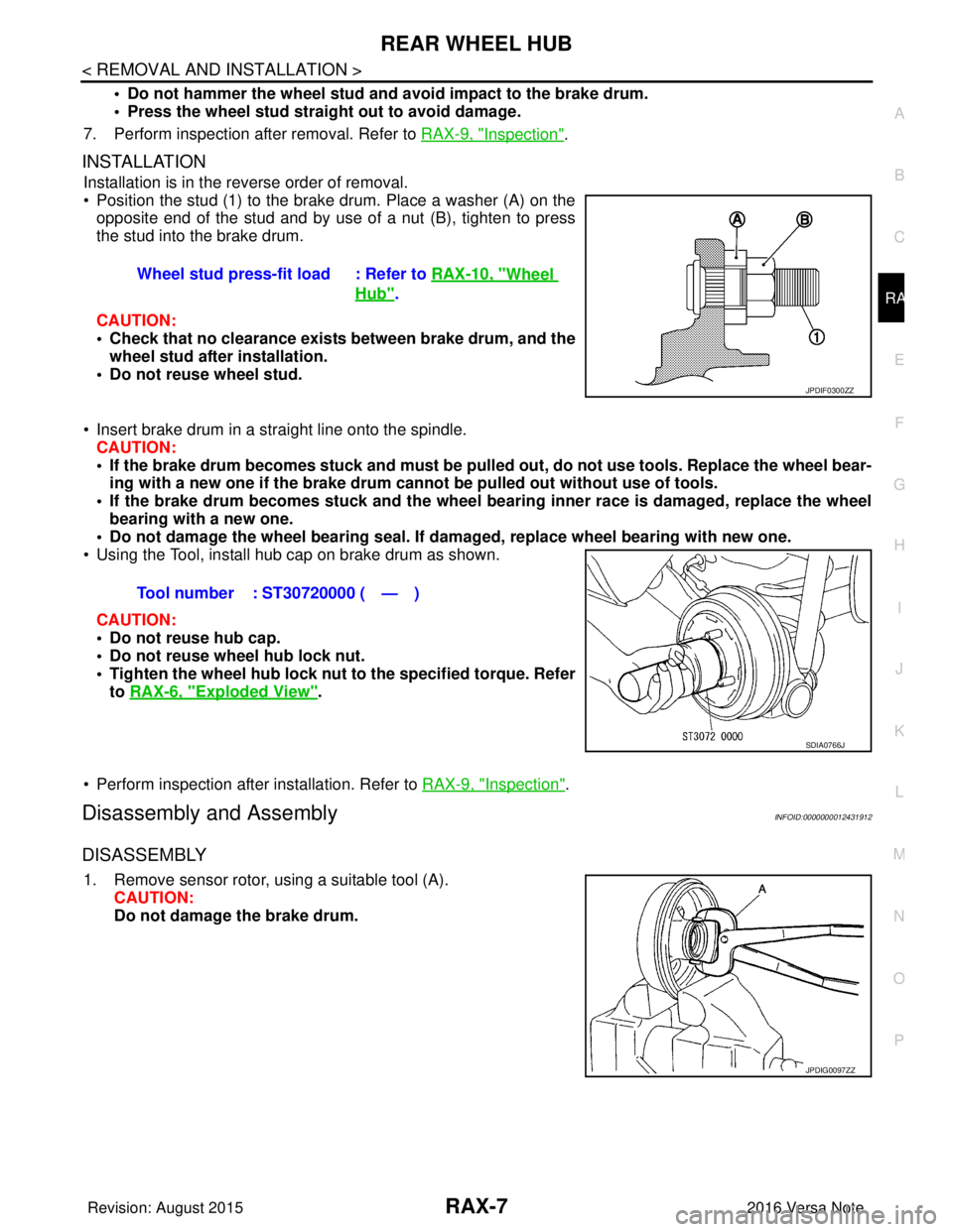
• Position the stud (1) to the brake drum. Place a washer (A) on the
opposite end of the stud and by use of a nut (B), tighten to press
the stud into the brake drum.
CAUTION:
• Check that no clearance exists between brake drum, and the wheel stud after installation.
• Do not reuse wheel stud.
• Insert brake drum in a straight line onto the spindle. CAUTION:
• If the brake drum becomes stuck and must be pulled out, do not use tools. Replace the wheel bear-
ing with a new one if the brake drum canno t be pulled out without use of tools.
• If the brake drum becomes stuck and the wheel bearing inner race is damaged, replace the wheel
bearing with a new one.
• Do not damage the wheel bearing seal. If da maged, replace wheel bearing with new one.
• Using the Tool, install hub cap on brake drum as shown.
CAUTION:
• Do not reuse hub cap.
• Do not reuse wheel hub lock nut.
• Tighten the wheel hub lock nut to the specified torque. Refer
to RAX-6, "
Exploded View".
• Perform inspection after installation. Refer to RAX-9, "
Inspection".
Disassembly and AssemblyINFOID:0000000012431912
DISASSEMBLY
1. Remove sensor rotor, using a suitable tool (A). CAUTION:
Do not damage the brake drum.Wheel stud press-fit load : Refer to
RAX-10, "
Wheel
Hub".
JPDIF0300ZZ
Tool number : ST30720000 ( — )
SDIA0766J
JPDIG0097ZZ
Revision: August 2015 2016 Versa Note
cardiagn.com
Page 2727 of 3641

REAR WHEEL HUBRAX-9
< REMOVAL AND INSTALLATION >
CEF
G H
I
J
K L
M A
B
RAX
N
O P
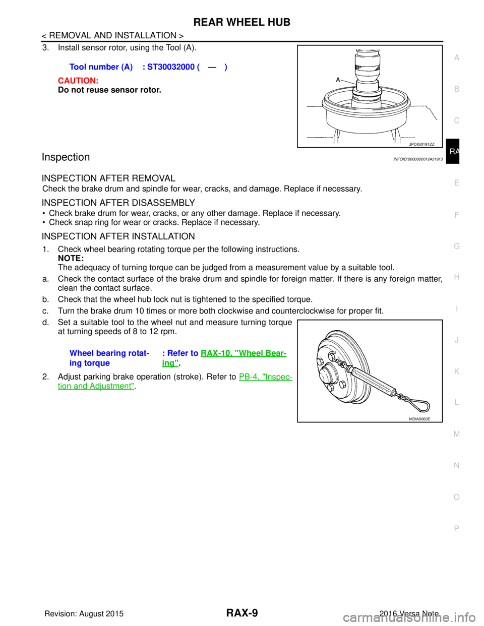
3. Install sensor rotor, using the Tool (A).
CAUTION:
Do not reuse sensor rotor.
InspectionINFOID:0000000012431913
INSPECTION AFTER REMOVAL
Check the brake drum and spindle for wear , cracks, and damage. Replace if necessary.
INSPECTION AFTER DISASSEMBLY
• Check brake drum for wear, cracks, or any other damage. Replace if necessary.
• Check snap ring for wear or cracks. Replace if necessary.
INSPECTION AFTER INSTALLATION
1. Check wheel bearing rotating torque per the following instructions. NOTE:
The adequacy of turning torque can be judged from a measurement value by a suitable tool.
a. Check the contact surface of the brake drum and spindle for foreign matter. If there is any foreign matter, clean the contact surface.
b. Check that the wheel hub lock nut is tightened to the specified torque.
c. Turn the brake drum 10 times or more bot h clockwise and counterclockwise for proper fit.
d. Set a suitable tool to the wheel nut and measure turning torque at turning speeds of 8 to 12 rpm.
2. Adjust parking brake operation (stroke). Refer to PB-4, "
Inspec-
tion and Adjustment".
Tool number (A) : ST30032000 ( — )
JPDIG0191ZZ
Wheel bearing rotat-
ing torque
: Refer to
RAX-10, "Wheel Bear-
ing".
MDIA0060E
Revision: August 2015 2016 Versa Note
cardiagn.com
Page 2741 of 3641

REAR SUSPENSION BEAMRSU-13
< REMOVAL AND INSTALLATION >
C
DF
G H
I
J
K L
M A
B
RSU
N
O P
REAR SUSPENSION BEAM
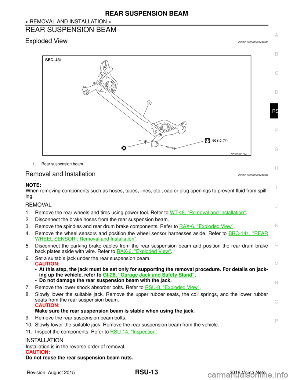
Exploded ViewINFOID:0000000012431930
Removal and InstallationINFOID:0000000012431931
NOTE:
When removing components such as hoses, tubes, lines, etc. , cap or plug openings to prevent fluid from spill-
ing.
REMOVAL
1. Remove the rear wheels and tires using power tool. Refer to WT-48, "Removal and Installation".
2. Disconnect the brake hoses from the rear suspension beam.
3. Remove the spindles and rear drum brake components. Refer to RAX-6, "
Exploded View".
4. Remove the wheel sensors and position the wheel sensor harnesses aside. Refer to BRC-141, "
REAR
WHEEL SENSOR : Removal and Installation".
5. Disconnect the parking brake cables from the rear suspension beam and position the rear drum brake
back plates aside with wire. Refer to RAX-6, "
Exploded View".
6. Set a suitable jack under the rear suspension beam. CAUTION:
• At this step, the jack must be set only for suppo rting the removal procedure. For details on jack-
ing up the vehicle, refer to GI-28, "
Garage Jack and Safety Stand".
• Do not damage the rear su spension beam with the jack.
7. Remove the lower shock absorber bolts. Refer to RSU-8, "
Exploded View".
8. Slowly lower the suitable jack. Remove the upper rubber seats, the coil springs, and the lower rubber seats from the rear suspension beam.
CAUTION:
Make sure the rear susp ension beam is stable when using the jack.
9. Remove the rear suspension beam bolts.
10. Slowly lower the suitable jack. Remove the rear suspension beam from the vehicle.
11. Inspect the components. Refer to RSU-14, "
Inspection".
INSTALLATION
Installation is in the reverse order of removal.
CAUTION:
Do not reuse the rear suspension beam nuts.
1. Rear suspension beam
AWEIA0347ZZ
Revision: August 2015 2016 Versa Note
cardiagn.com
Page 2742 of 3641

RSU-14
< REMOVAL AND INSTALLATION >
REAR SUSPENSION BEAM
• Perform the final tightening of the rear suspension beam nuts and bolts under unladen conditions with thetires on level ground.
• Adjust the parking brake. Refer to PB-4, "
Inspection and Adjustment".
• Fill the hydraulic brake system. Refer to BR-12, "
Refilling".
• Bleed the hydraulic brake system. Refer to BR-13, "
Bleeding Brake System".
• Complete the inspection. Refer to BR-12, "
Inspection".
InspectionINFOID:0000000012431932
INSPECTION AFTER REMOVAL
Check the rear suspension beam for deformation, cracks or damage. Replace the parts if necessary.
INSPECTION AFTER INSTALLATION
1. Check the wheel sensor harness to be sure the connectors are fully seated.
2. Check the neutral position of the steering angle sensor. Refer to BRC-55, "
ADJUSTMENT OF STEERING
ANGLE SENSOR NEUTRAL POSITION : Description".
3. Check the wheel alignment. Refer to RSU-6, "
Inspection".
Revision: August 2015 2016 Versa Note
cardiagn.com
Page 2876 of 3641
![NISSAN NOTE 2016 Service Repair Manual DIAGNOSIS SYSTEM (BCM)SEC-19
< SYSTEM DESCRIPTION > [WITH INTELLIGENT KEY SYSTEM]
C
D
E
F
G H
I
J
L
M A
B
SEC
N
O P
INTELLIGENT KEY
INTELLIGENT KEY : CONSULT Func tion (BCM - INTELLIGENT KEY)INFOID:00 NISSAN NOTE 2016 Service Repair Manual DIAGNOSIS SYSTEM (BCM)SEC-19
< SYSTEM DESCRIPTION > [WITH INTELLIGENT KEY SYSTEM]
C
D
E
F
G H
I
J
L
M A
B
SEC
N
O P
INTELLIGENT KEY
INTELLIGENT KEY : CONSULT Func tion (BCM - INTELLIGENT KEY)INFOID:00](/manual-img/5/57363/w960_57363-2875.png)
DIAGNOSIS SYSTEM (BCM)SEC-19
< SYSTEM DESCRIPTION > [WITH INTELLIGENT KEY SYSTEM]
C
D
E
F
G H
I
J
L
M A
B
SEC
N
O P
INTELLIGENT KEY
INTELLIGENT KEY : CONSULT Func tion (BCM - INTELLIGENT KEY)INFOID:0000000012542526
SELF DIAGNOSTIC RESULT
Refer to BCS-50, "DTCIndex".
DATA MONITOR
ACTIVE TEST
Monitor Item [Unit] Main Description
REQ SW -DR [On/Off] ×Indicates condition of door request switch LH.
REQ SW -AS [On/Off] ×Indicates condition of door request switch RH.
REQ SW -BD/TR [On/Off] ×Indicates condition of back door request switch.
PUSH SW [On/Off] Indicates condition of push-button ignition switch.
CLUCH SW [On/Off] ×Indicates condition of clutch interlock switch.
BRAKE SW 1 [On/Off] ×Indicates condition of brake switch.
BRAKE SW 2 [On/Off] Indicates condition of brake switch.
DETE/CANCL SW [On/Off] ×Indicates condition of P (park) position.
SFT PN/N SW [On/Off] ×Indicates condition of P (park) or N (neutral) position.
UNLK SEN -DR [On/Off] ×Indicates condition of door unlock sensor.
PUSH SW -IPDM [On/Off] Indicates condition of push-button ignition switch received from IPDM E/R on
CAN communication line.
IGN RLY1 -F/B [On/Off] Indicates condition of ignition relay 1 received from IPDM E/R on CAN commu-
nication line.
DETE SW -IPDM [On/Off] Indicates condition of detent switch received from TCM on CAN communication
line.
SFT PN -IPDM [On/Off] Indicates condition of P (park) or N (neutral) position from TCM on CAN com-
munication line.
SFT P -MET [On/Off] Indicates condition of P (park) position from TCM on CAN communication line.
SFT N -MET [On/Off] Indicates condition of N (neutral) position from IPDM E/R on CAN communica-
tion line.
ENGINE STATE [Stop/Start/Crank/Run] ×Indicates condition of engine state from ECM on CAN communication line.
VEH SPEED 1 [mph/km/h] ×Indicates condition of vehicle speed si
gnal received from ABS on CAN commu-
nication line.
VEH SPEED 2 [mph/km/h] ×Indicates condition of vehicle speed signal received from combination meter on
CAN communication line.
DOOR STAT -DR [LOCK/READY/UNLK] ×Indicates condition of driver side door status.
DOOR STAT -AS [LOCK/READY/UNLK] ×Indicates condition of passenger side door status.
ID OK FLAG [Set/Reset] Indicates condition of Intelligent Key ID.
PRMT ENG STRT [Set/Reset] Indicates condition of engine start possibility.
RKE OPE COUN1 [0-19] ×When remote keyless entry receiver receives the signal transmitted while oper-
ating on Intelligent Key, the numerical value start changing.
RKE OPE COUN2 [0-19] ×When remote keyless entry receiver receives the signal transmitted while oper-
ating on Intelligent Key, the numerical value start changing.
RKE-LOCK [On/Off] Indicates condition of lock signal from Intelligent Key.
RKE-UNLOCK [On/Off] Indicates condition of unlock signal from Intelligent Key.
RKE-PANIC [On/Off] Indicates condition of panic signal from Intelligent Key.
RKE-MODE CHG [On/Off] Indicates condition of mode change signal from Intelligent Key.
Revision: August 2015 2016 Versa Note
cardiagn.com
Page 3243 of 3641

TM-2
INPUT SHAFT AND GEAR ...............................45
Exploded View ..................................................... ...45
Disassembly ...........................................................45
Assembly ................................................................45
Inspection ...............................................................45
MAINSHAFT AND GEAR ..................................47
Exploded View ..................................................... ...47
Disassembly ...........................................................47
Assembly ................................................................49
Inspection ...............................................................50
FINAL DRIVE .....................................................52
Exploded View ..................................................... ...52
Disassembly ...........................................................52
Assembly ................................................................52
Inspection ...............................................................52
SERVICE DATA AND SPECIFICATIONS
(SDS) ........................................................ ...
54
SERVICE DATA AND SPECIFICATIONS
(SDS) ............................................................... ...
54
General Specifications ......................................... ...54
CVT: RE0F11A
PRECAUTION .............. ...............................
55
PRECAUTIONS .............................................. ...55
Precaution for Supplemental Restraint System
(SRS) "AIR BAG" and "SEAT BELT PRE-TEN-
SIONER" .............................................................. ...
55
Precaution for Procedure without Cowl Top Cover ...55
Precaution for TCM, Transaxle Assembly or Con-
trol Valve Replacement ..........................................
55
Precaution for G Sensor Removal/Installation or
Replacement ..........................................................
55
General Precautions ...............................................56
On Board Diagnosis (OBD) System of CVT and
Engine ....................................................................
57
Removal and Installation Procedure for CVT Unit
Connector ...............................................................
57
PREPARATION ...........................................59
PREPARATION .............................................. ...59
Special Service Tools .......................................... ...59
Commercial Service Tools ......................................59
SYSTEM DESCRIPTION ............................61
COMPONENT PARTS .................................... ...61
CVT CONTROL SYSTEM ...................................... ...61
CVT CONTROL SYSTEM : Component Parts Lo-
cation ......................................................................
61
CVT CONTROL SYSTEM : TCM ...........................63
CVT CONTROL SYSTEM : ROM Assembly ....... ...63
CVT CONTROL SYSTEM : Transmission Range
Switch .................................................................. ...
63
CVT CONTROL SYSTEM : Primary Speed Sen-
sor ........................................................................ ...
63
CVT CONTROL SYSTEM : Secondary Speed
Sensor .....................................................................
63
CVT CONTROL SYSTEM : Output Speed Sensor ...64
CVT CONTROL SYSTEM : CVT Fluid Tempera-
ture Sensor .......................................................... ...
64
CVT CONTROL SYSTEM : Secondary Pressure
Sensor .................................................................. ...
65
CVT CONTROL SYSTEM : Primary Pressure So-
lenoid Valve ......................................................... ...
65
CVT CONTROL SYSTEM : Low Brake Solenoid
Valve .......................................................................
65
CVT CONTROL SYSTEM : High Clutch & Re-
verse Brake Solenoid Valve ....................................
66
CVT CONTROL SYSTEM : Torque Converter
Clutch Solenoid Valve .............................................
66
CVT CONTROL SYSTEM : Line Pressure Sole-
noid Valve ............................................................ ...
66
CVT CONTROL SYSTEM : G Sensor ....................66
CVT CONTROL SYSTEM : Overdrive Control
Switch .....................................................................
66
CVT CONTROL SYSTEM : O/D OFF Indicator
Lamp .......................................................................
66
CVT CONTROL SYSTEM : Shift Position Indica-
tor ............................................................................
68
CVT CONTROL SYSTEM : Malfunction Indicator
Lamp (MIL) ..............................................................
68
SHIFT LOCK SYSTEM ..............................................68
SHIFT LOCK SYSTEM : Co mponent Parts Loca-
tion ....................................................................... ...
68
STRUCTURE AND OPERATION ......................70
TRANSAXLE .......................................................... ...70
TRANSAXLE : Cross-Sectional View .....................70
TRANSAXLE : Transaxle Mechanism ... .................70
TRANSAXLE : Operation Stat us .............................72
TRANSAXLE : Oil Pressure System .......................73
TRANSAXLE : Component De scription ..................73
FLUID COOLER & FLUID WARMER SYSTEM ..... ...74
FLUID COOLER & FLUID WARMER SYSTEM :
System Description .................................................
74
SHIFT LOCK SYSTEM ..............................................74
SHIFT LOCK SYSTEM : Syst em Description .........75
KEY LOCK SYSTEM .............................................. ...75
KEY LOCK SYSTEM : System Description ............75
SYSTEM ......................................................... ...76
CVT CONTROL SYSTEM .........................................76
CVT CONTROL SYSTEM : System Description . ...76
CVT CONTROL SYSTEM : Fail-safe ......................78
CVT CONTROL SYSTEM : Protection Control .......80
LINE PRESSURE CONTROL ................................ ...81
LINE PRESSURE CONTROL : System Descrip-
tion ....................................................................... ...
82
Revision: August 2015 2016 Versa Note
cardiagn.com
Page 3245 of 3641

TM-4
P0705 TRANSMISSION RANGE SENSOR A .144
DTC Logic ..............................................................144
Diagnosis Procedure .............................................144
Component Inspection (Transmission Range
Switch) ...................................................................
148
P0706 TRANSMISSION RANGE SENSOR A .150
DTC Logic ..............................................................150
Diagnosis Procedure .............................................150
Component Inspection (Transmission Range
Switch) ...................................................................
152
P0711 TRANSMISSION FLUID TEMPERA-
TURE SENSOR A ............................................
153
DTC Logic ............................................................ ..153
Diagnosis Procedure .............................................156
Component Inspection (CVT Fluid Temperature
Sensor) ..................................................................
156
P0712 TRANSMISSION FLUID TEMPERA-
TURE SENSOR A ............................................
157
DTC Logic ............................................................ ..157
Diagnosis Procedure .............................................157
Component Inspection (CVT Fluid Temperature
Sensor) ..................................................................
157
P0713 TRANSMISSION FLUID TEMPERA-
TURE SENSOR A ............................................
159
DTC Logic ............................................................ ..159
Diagnosis Procedure .............................................159
Component Inspection (CVT Fluid Temperature
Sensor) ..................................................................
160
P0715 INPUT SPEED SENSOR A ..................161
DTC Logic ............................................................ ..161
Diagnosis Procedure .............................................161
P0720 OUTPUT SPEED SENSOR ..................164
DTC Logic ............................................................ ..164
Diagnosis Procedure .............................................164
P0740 TORQUE CONVERTER .......................167
DTC Logic ............................................................ ..167
Diagnosis Procedure .............................................168
Component Inspection (Torque Converter Clutch
Solenoid Valve) .....................................................
168
P0743 TORQUE CONVERTER .......................169
DTC Logic ............................................................ ..169
Diagnosis Procedure .............................................170
Component Inspection (Torque Converter Clutch
Solenoid Valve) .....................................................
170
P0744 TORQUE CONVERTER .......................171
DTC Logic ............................................................ ..171
Diagnosis Procedure .............................................172
Component Inspection (Torque Converter Clutch
Solenoid Valve) .....................................................
172
P0746 PRESSURE CONTROL SOLENOID A .173
DTC Logic ............................................................ ..173
Diagnosis Procedure ............................................ .174
Component Inspection (Line Pressure Solenoid
Valve) ....................................................................
174
P0846 TRANSMISSION FLUID PRESSURE
SEN/SW B ........................................................
175
DTC Logic .............................................................175
Diagnosis Procedure .............................................175
P0847 TRANSMISSION FLUID PRESSURE
SEN/SW B ........................................................
177
DTC Logic .............................................................177
Diagnosis Procedure .............................................177
P0848 TRANSMISSION FLUID PRESSURE
SEN/SW B ........................................................
179
DTC Logic .............................................................179
Diagnosis Procedure .............................................179
P0863 TCM COMMUNICATION .......................181
DTC Logic .............................................................181
Diagnosis Procedure .............................................181
P0890 TCM .......................................................182
DTC Logic .............................................................182
Diagnosis Procedure .............................................182
P0962 PRESSURE CONTROL SOLENOID A ..184
DTC Logic ............................................................ .184
Diagnosis Procedure .............................................184
Component Inspection (Line Pressure Solenoid
Valve) ....................................................................
184
P0963 PRESSURE CONTROL SOLENOID A ..186
DTC Logic ............................................................ .186
Diagnosis Procedure .............................................186
Component Inspection (Line Pressure Solenoid
Valve) ....................................................................
186
P0965 PRESSURE CONTROL SOLENOID B ..188
DTC Logic ............................................................ .188
Diagnosis Procedure .............................................188
P0966 PRESSURE CONTROL SOLENOID B ..189
DTC Logic ............................................................ .189
Diagnosis Procedure .............................................189
Component Inspection (Primary Pressure Sole-
noid Valve) ............................................................
189
P0967 PRESSURE CONTROL SOLENOID B ..191
DTC Logic ............................................................ .191
Diagnosis Procedure .............................................191
Component Inspection (Primary Pressure Sole-
noid Valve) ............................................................
191
P0998 SHIFT SOLENOID F .............................193
DTC Logic .............................................................193
Diagnosis Procedure .............................................193
Component Inspection (Low Brake Solenoid
Valve) ....................................................................
193
Revision: August 2015 2016 Versa Note
cardiagn.com
Page 3246 of 3641

TM-5
CEF
G H
I
J
K L
M A
B
TM
N
O P
P0999 SHIFT SOLENOID F .............................195
DTC Logic ........................................................... ..195
Diagnosis Procedure .............................................195
Component Inspection (Low Brake Solenoid
Valve) ....................................................................
195
P099B SHIFT SOLENOID G ............................197
DTC Logic ........................................................... ..197
Diagnosis Procedure .............................................197
Component Inspection (High Clutch & Reverse
Brake Solenoid Valve) ...........................................
197
P099C SHIFT SOLENOID G ............................199
DTC Logic ........................................................... ..199
Diagnosis Procedure .............................................199
Component Inspection (High Clutch & Reverse
Brake Solenoid Valve) ...........................................
199
P1586 G SENSOR ............................................201
DTC Logic .............................................................201
Diagnosis Procedure .............................................201
P1588 G SENSOR ............................................204
DTC Logic .............................................................204
Diagnosis Procedure .............................................204
P2765 CLUTCH B SPEED SENSOR ...............206
DTC Logic ........................................................... ..206
Diagnosis Procedure .............................................206
P2857 CLUTCH A PRESSURE .......................209
DTC Logic ........................................................... ..209
Diagnosis Procedure .............................................209
P2858 CLUTCH B PRESSURE .......................210
DTC Logic ........................................................... ..210
Diagnosis Procedure .............................................210
P2859 CLUTCH A PRESSURE .......................211
DTC Logic ........................................................... ..211
Diagnosis Procedure .............................................212
P285A CLUTCH B PRESSURE .......................213
DTC Logic ........................................................... ..213
Diagnosis Procedure .............................................214
MAIN POWER SUPPLY AND GROUND CIR-
CUIT ..................................................................
215
Diagnosis Procedure ........................................... ..215
OVERDRIVE CONTROL SWITCH ...................217
Component Function Check ................................ ..217
Diagnosis Procedure .............................................217
Component Inspection (Overdrive Control Switch)
..
218
OD OFF INDICATOR LAMP ............................219
Component Function Check ..................................219
Diagnosis Procedure .............................................219
SHIFT POSITION INDICATOR CIRCUIT .........220
Component Parts Function Inspection ................ ..220
Diagnosis Procedure ........................................... ..220
SHIFT LOCK SYSTEM ...................................221
Component Function Check ..................................221
Diagnosis Procedure .............................................221
SYMPTOM DIAGNOSIS ............................223
CVT CONTROL SYSTEM ...............................223
Symptom Table ................................................... ..223
PERIODIC MAINTENANCE ......................228
CVT FLUID ......................................................228
Inspection ............................................................ ..228
Replacement .........................................................228
Adjustment .............................................................229
REMOVAL AND INSTALLATION .............231
CVT SHIFT SELECTOR ..................................231
Exploded View ..................................................... ..231
Removal and Installation .......................................231
Disassembly and Assembly ...................................232
Inspection ..............................................................232
CONTROL CABLE ..........................................234
Exploded View .......................................................234
Removal and Installation .......................................234
Inspection and Adjustment ....................................236
KEY INTERLOCK CABLE ..............................237
Exploded View .......................................................237
Removal and Installation .......................................237
Inspection ..............................................................238
TCM .................................................................239
Exploded View .......................................................239
Removal and Installation .......................................239
Adjustment .............................................................239
AIR BREATHER HOSE ..................................240
Removal and Installation .......................................240
G SENSOR ......................................................241
Exploded View .......................................................241
Removal and Installation .......................................241
Adjustment .............................................................241
OIL PAN, CONTROL VALVE .........................242
Exploded View .......................................................242
Removal and Installation .......................................242
Inspection and Adjustment ....................................245
PRIMARY SPEED SENSOR ...........................246
Exploded View .......................................................246
Removal and Installation .......................................246
Inspection and Adjustment ....................................246
SECONDARY SPEED SENSOR ....................247
Exploded View .......................................................247
Removal and Installation .......................................247
Revision: August 2015 2016 Versa Note
cardiagn.com