2016 MERCEDES-BENZ GLS SUV brake
[x] Cancel search: brakePage 373 of 397
The wear patterns on the front and rear tyres
differ depending on the operating conditions.
Interchange the wheels before a clear wear pat-
tern has formed on the tyres. Front tyres typi-
cally wear more on the shoulders, while rear
tyres wear more in the centre.
On vehicles that have the same size front and
rear wheels, you can interchange the wheels
every 5,000 to 10,000 km depending on the
degree of tyre wear. Ensure that the direction of
rotation is maintained.
Clean the contact surfaces of the wheel and the
brake disc thoroughly every time a wheel is
interchanged. Check the tyre pressure and, if
necessary, restart the tyre pressure loss warn-
ing system or the tyre pressure monitor
(Y page 366). Direction of rotation
Tyres with a specified direction of rotation have additional benefits, e.g. if there is a risk of aqua- planing. These advantages can only be gained if
the tyres are fitted corresponding to the direc-
tion of rotation.
An arrow on the sidewall of the tyre indicates its correct direction of rotation. Storing wheels
Store wheels that are not being used in a cool,
dry and preferably dark place. Protect the tyres
against oil, grease, petrol and diesel. Fitting a wheel
Preparing the vehicle X
Vehicles with an emergency spare wheel:
when fitting the emergency spare wheel in the
event of a flat tyre, observe the additional
notes on vehicle preparation under "Flat tyre"
(Y page 346).
X Stop the vehicle on solid, non-slippery and
level ground.
X Apply the electric parking brake manually.
X Move the front wheels to the straight-ahead
position.
X Vehicles with automatic transmission:
shift the transmission to position
P.X
Vehicles with the AIRMATIC package:
make sure that the normal vehicle level is
selected (Y page 198).
X Vehicles with the Off-Road Engineering
package:
make sure that the normal level is
selected (Y page 192).
X Switch off the engine.
X Vehicles without KEYLESS-GO: remove the
key from the ignition lock.
X Vehicles with KEYLESS-GO: open the driv-
er's door.
The on-board electronics now have status 0.
This is the same as the key having been
removed.
X Vehicles with KEYLESS-GO: remove the
Start/Stop button from the ignition lock
(Y page 148).
X If included in the vehicle equipment, remove
the tyre-change tool kit from the vehicle.
X Safeguard the vehicle against rolling away.
i Apart from certain country-specific varia-
tions, vehicles are not equipped with a tyre-
change tool kit. For information on which
tools are required to perform a wheel change
on your vehicle, consult a Mercedes-Benz
Service Centre.
Necessary tyre-changing tools may include,
for example:
R jack
R wheel chock
R wheel wrench
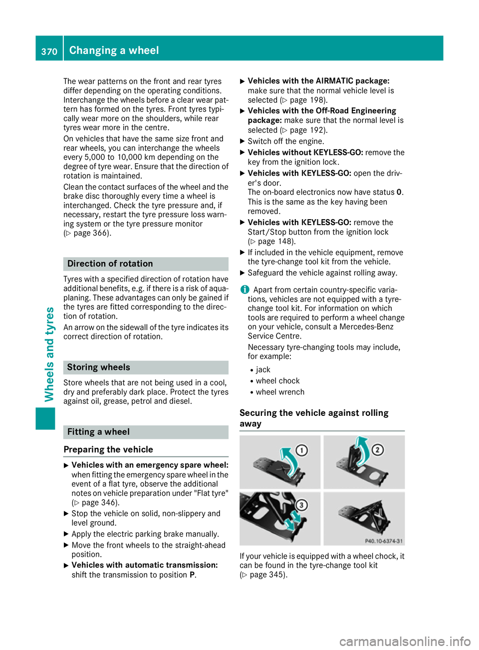
Securing the vehicle against rolling
away If your vehicle is equipped with a wheel chock, it
can be found in the tyre-change tool kit
(Y page 345). 370
Changing a wheelWheels and tyres
Page 374 of 397
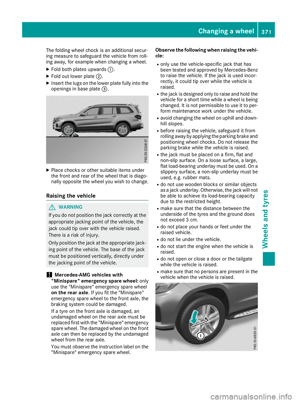
The folding wheel chock is an additional secur-
ing measure to safeguard the vehicle from roll-
ing away, for example when changing a wheel.
X Fold both plates upwards :.
X Fold out lower plate ;.
X Insert the lugs on the lower plate fully into the
openings in base plate =.X
Place chocks or other suitable items under
the front and rear of the wheel that is diago-
nally opposite the wheel you wish to change.
Raising the vehicle G
WARNING
If you do not position the jack correctly at the appropriate jacking point of the vehicle, the
jack could tip over with the vehicle raised.
There is a risk of injury.
Only position the jack at the appropriate jack-
ing point of the vehicle. The base of the jack
must be positioned vertically, directly under
the jacking point of the vehicle.
! Mercedes-AMG vehicles with
"Minispare" emergency spare wheel: only
use the "Minispare" emergency spare wheel
on the rear axle. If you fit the "Minispare"
emergency spare wheel to the front axle, the
braking system could be damaged.
If a tyre on the front axle is damaged, an
undamaged wheel on the rear axle must be
replaced first with the "Minispare" emergency spare wheel. The damaged wheel on the front
axle can then be replaced by the undamaged
wheel from the rear axle.
You must observe the instruction label on the "Minispare" emergency spare wheel. Observe the following when raising the vehi-
cle:
R only use the vehicle-specific jack that has
been tested and approved by Mercedes-Benz
to raise the vehicle. If the jack is used incor-
rectly, it could tip over while the vehicle is
raised.
R the jack is designed only to raise and hold the
vehicle for a short time while a wheel is being
changed. It is not permissible to use it to per- form maintenance work under the vehicle.
R avoid changing the wheel on uphill and down-
hill slopes.
R before raising the vehicle, safeguard it from
rolling away by applying the parking brake and
positioning wheel chocks. Do not release theparking brake while the vehicle is raised.
R the jack must be placed on a firm, flat and
non-slip surface. On a loose surface, a large,
flat load-bearing underlay must be used. On a
slippery surface, a non-slip underlay must be
used, e.g. rubber mats.
R do not use wooden blocks or similar objects
as a jack underlay. Otherwise, the jack will not
be able to achieve its load-bearing capacity
due to the restricted height.
R make sure that the distance between the
underside of the tyres and the ground does
not exceed 3 cm.
R do not place your hands or feet under the
raised vehicle.
R do not lie under the vehicle.
R do not start the engine when the vehicle is
raised.
R do not open or close a door or the tailgate
while the vehicle is raised.
R make sure that no persons are present in the
vehicle when the vehicle is raised. Changing a wheel
371Wheels and tyres Z
Page 375 of 397
X
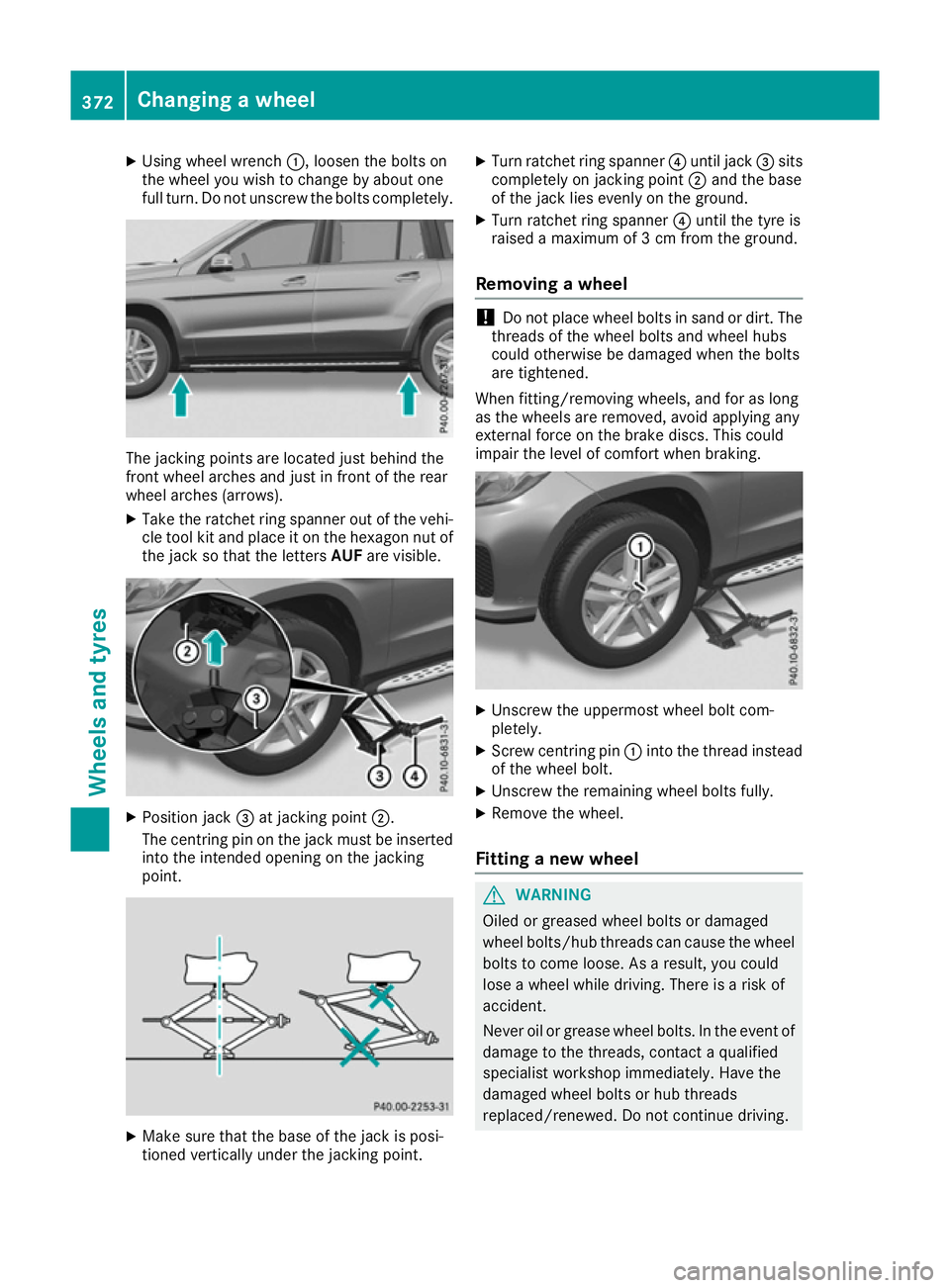
Using wheel wrench :, loosen the bolts on
the wheel you wish to change by about one
full turn. Do not unscrew the bolts completely. The jacking points are located just behind the
front wheel arches and just in front of the rear
wheel arches (arrows).
X Take the ratchet ring spanner out of the vehi-
cle tool kit and place it on the hexagon nut of
the jack so that the letters AUFare visible. X
Position jack =at jacking point ;.
The centring pin on the jack must be inserted into the intended opening on the jacking
point. X
Make sure that the base of the jack is posi-
tioned vertically under the jacking point. X
Turn ratchet ring spanner ?until jack =sits
completely on jacking point ;and the base
of the jack lies evenly on the ground.
X Turn ratchet ring spanner ?until the tyre is
raised a maximum of 3 cm from the ground.
Removing a wheel !
Do not place wheel bolts in sand or dirt. The
threads of the wheel bolts and wheel hubs
could otherwise be damaged when the bolts
are tightened.
When fitting/removing wheels, and for as long
as the wheels are removed, avoid applying any
external force on the brake discs. This could
impair the level of comfort when braking. X
Unscrew the uppermost wheel bolt com-
pletely.
X Screw centring pin :into the thread instead
of the wheel bolt.
X Unscrew the remaining wheel bolts fully.
X Remove the wheel.
Fitting a new wheel G
WARNING
Oiled or greased wheel bolts or damaged
wheel bolts/hub threads can cause the wheel bolts to come loose. As a result, you could
lose a wheel while driving. There is a risk of
accident.
Never oil or grease wheel bolts. In the event ofdamage to the threads, contact a qualified
specialist workshop immediately. Have the
damaged wheel bolts or hub threads
replaced/renewed. Do not continue driving. 372
Changing a wheelWheels and tyres
Page 376 of 397
G
WARNING
If you tighten the wheel bolts or wheel nuts
when the vehicle is raised, the jack could tip
over. There is a risk of injury.
Only tighten the wheel bolts or wheel nuts
when the vehicle is on the ground.
It is imperative to observe the instructions and
safety notes on "Changing a wheel"
(Y page 369).
Only use wheel bolts that have been designed
for the wheel and the vehicle. For safety rea-
sons, Mercedes-Benz recommends that you
only use wheel bolts which have been approved for Mercedes-Benz vehicles and the respective
wheel.
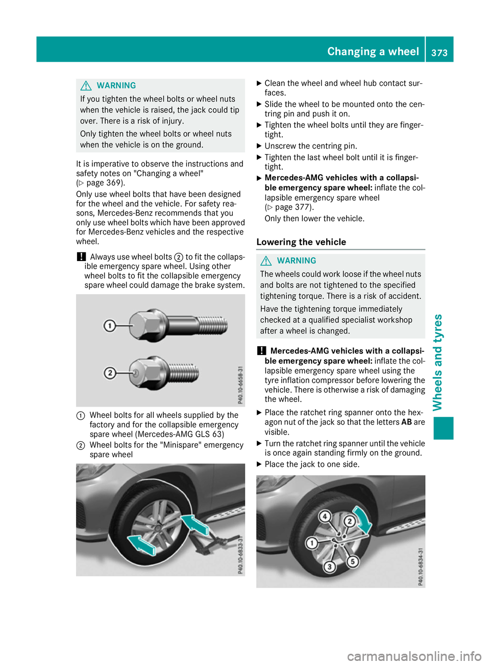
! Always use wheel bolts
;to fit the collaps-
ible emergency spare wheel. Using other
wheel bolts to fit the collapsible emergency
spare wheel could damage the brake system. :
Wheel bolts for all wheels supplied by the
factory and for the collapsible emergency
spare wheel (Mercedes-AMG GLS 63)
; Wheel bolts for the "Minispare" emergency
spare wheel X
Clean the wheel and wheel hub contact sur-
faces.
X Slide the wheel to be mounted onto the cen-
tring pin and push it on.
X Tighten the wheel bolts until they are finger-
tight.
X Unscrew the centring pin.
X Tighten the last wheel bolt until it is finger-
tight.
X Mercedes-AMG vehicles with a collapsi-
ble emergency spare wheel:
inflate the col-
lapsible emergency spare wheel
(Y page 377).
Only then lower the vehicle.
Lowering the vehicle G
WARNING
The wheels could work loose if the wheel nuts and bolts are not tightened to the specified
tightening torque. There is a risk of accident.
Have the tightening torque immediately
checked at a qualified specialist workshop
after a wheel is changed.
! Mercedes-AMG vehicles with a collapsi-
ble emergency spare wheel: inflate the col-
lapsible emergency spare wheel using the
tyre inflation compressor before lowering the vehicle. There is otherwise a risk of damaging
the wheel.
X Place the ratchet ring spanner onto the hex-
agon nut of the jack so that the letters ABare
visible.
X Turn the ratchet ring spanner until the vehicle
is once again standing firmly on the ground.
X Place the jack to one side. Changing a wheel
373Wheels and tyres Z
Page 384 of 397

Vehicle identification plate (example: vehicles with
a trailer tow hitch – all other countries)
: Vehicle manufacturer (Daimler AG)
; EU type approval number (for certain coun-
tries only)
= VIN
? Maximum gross vehicle weight (kg)
A Maximum gross vehicle weight of vehicle
combination (kg)
B Permissible front axle load (kg)
C Permissible rear axle load (kg)
D Paint code
i The data shown on the vehicle identification
plate is sample data. This data is different for every vehicle and may differ from the data
shown here. You can find the data applicable to your vehicle on the vehicle's identification
plate. Vehicle identification number (VIN)
X
Open the front right-hand door.
X Open cover :in the direction of the arrow
and remove it.
The VIN can be seen.
The VIN can also be found on the vehicle iden-
tification plate (Y page 380). Engine number
The engine number is stamped into the crank-
case. You can obtain further information from
any qualified specialist workshop. Service products and capacities
Important safety notes
G
WARNING
Service product can be poisonous and haz-
ardous to health. There is a risk of injury.
Observe the instructions on the respective
original container when using, storing and dis- posing off service products. Always store ser-
vice products in the sealed original container. Always keep service products out of the reach
of children. H
Environmental note
Dispose of service products in an environ-
mentally-responsible manner.
Service products include the following:
R fuels
R exhaust gas aftertreatment additives, e.g.
AdBlue ®
R lubricants (e.g. engine oil, transmission oil)
R coolant
R brake fluid
R windscreen washer fluid
R climate control system refrigerant
Components and service products must be
matched. Only use products recommended by
Mercedes-Benz. Damage caused by the use of
products that have not been recommended is
not covered by the Mercedes-Benz warranty or
goodwill gestures. They are listed in this
Mercedes-Benz Owner's Manual in the appro-
priate section.
You can identify service products approved by
Mercedes-Benz by the following inscriptions on
the container:
R MB-Freigabe (e.g. MB-Freigabe 229.51)
R MB-Approval (e.g. MB-Approval 229.51)
Other designations or recommendations indi-
cate a level of quality or a specification in
accordance with an MB Sheet Number (e.g. MB Service products and capacities
381Technical data Z
Page 389 of 397

Brake fluid
G
WARNING
The brake fluid continuously absorbs mois-
ture from the air. This results in the boiling
point of the brake fluid lowering. If the boiling
point of the brake fluid is too low, vapour
pockets may form when the brakes are sub-
jected to a heavy load. This would impair brak- ing efficiency. There is a risk of an accident.
Have the brake fluid renewed at the prescri-
bed intervals.
Comply with the important safety notes for ser- vice products when handling brake fluid
(Y page 381).
The brake fluid change intervals can be found in the Service Booklet.
Only use brake fluid approved by Mercedes-
Benz according to MB-Freigabe or MB-Approval
331.0.
Information about approved brake fluid can be
obtained at any qualified specialist workshop or
on the Internet at
http://bevo.mercedes-benz.com.
i Have the brake fluid regularly replaced at a
qualified specialist workshop in accordance
with the replacement intervals and the
replacement confirmed in the Service Book-
let. Coolant
Important safety notes G
WARNING
If antifreeze comes into contact with hot com- ponents in the engine compartment, it may
ignite. There is a risk of fire and injury.
Let the engine cool down before you top up
the antifreeze. Make sure that antifreeze is
not spilled next to the filler neck. Thoroughly
clean the antifreeze from components before
starting the engine.
! Only add coolant that has been premixed
with the desired antifreeze protection. You
could otherwise damage the engine. Further information on coolants can be found
in the Mercedes-Benz Specifications for Ser-
vice Products, MB Specifications for Service
Products 310.1, e.g. on the Internet at
http://bevo.mercedes-benz.com. Or contact
a qualified specialist workshop.
! Always use a suitable coolant mixture, even
in countries where high temperatures prevail.
Otherwise, the engine cooling system is not
sufficiently protected from corrosion and
overheating.
i Have the coolant regularly replaced at a
qualified specialist workshop and the replace-
ment confirmed in the Service Booklet.
Observe the important safety notes for service
products when handling coolant (Y page 381).
The coolant is a mixture of water and anti-
freeze/anti-corrosion additive. It is responsible
for the following:
R corrosion protection
R antifreeze protection
R raising the boiling point
If antifreeze/corrosion inhibitor is present in the
correct concentration, the boiling point of the
coolant during operation will be approximately
130 †.
The antifreeze/anti-corrosion additive concen-
tration in the engine cooling system should:
R be at least 50%. This will protect the engine
cooling system against freezing down to
approximately -37 †.
R not exceed 55% (antifreeze protection down
to -45 †). Heat will otherwise not be dissipa- ted as effectively.
Mercedes-Benz recommends an antifreeze/
anti-corrosion additive concentrate in accord-
ance with MB Specifications for Service Prod-
ucts 310.1.
i When the vehicle is first delivered, it is filled
with a coolant mixture that ensures adequate
antifreeze and corrosion protection.
i The coolant is checked at every mainte-
nance interval at a qualified specialist work-
shop. 386
Service products and capacitiesTechnical data
Page 393 of 397
i
If the load on the front axle is reduced when
pulling away on a steep uphill slope, the front
wheels have a tendency to spin. 4ETS recog-
nises this and brakes the wheels accordingly. The rear wheel torque is increased and it is
easier to pull away.
For further information about maximum gradi-
ent-climbing capability, see (Y page 180).Trailer tow hitch
Trailer loads
Trailer loads, noseweights and axle
loads !
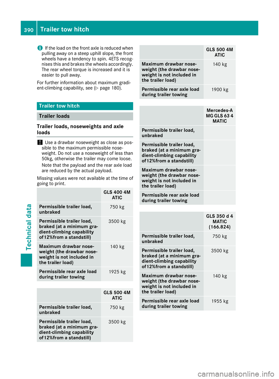
Use a drawbar noseweight as close as pos-
sible to the maximum permissible nose-
weight. Do not use a noseweight of less than
50kg, otherwise the trailer may come loose.
Note that the payload and the rear axle load
are reduced by the actual payload.
Missing values were not available at the time of going to print. GLS 400 4M
ATIC Permissible trailer load,
unbraked
750 kg
Permissible trailer load,
braked (at a minimum gra-
dient-climbing capability
of12%from a standstill)
3500 kg
Maximum drawbar nose-
weight (the drawbar nose-
weight is not included in
the trailer load)
140 kg
Permissible rear axle load
during trailer towing
1925 kg
GLS 500 4M
ATIC Permissible trailer load,
unbraked
750 kg
Permissible trailer load,
braked (at a minimum gra-
dient-climbing capability
of12%from a standstill)
3500 kg GLS 500 4M
ATIC Maximum drawbar nose-
weight (the drawbar nose-
weight is not included in
the trailer load)
140 kg
Permissible rear axle load
during trailer towing
1900 kg
Mercedes‑A
MG GLS 63 4 MATIC Permissible trailer load,
unbraked
Permissible trailer load,
braked (at a minimum gra-
dient-climbing capability
of12%from a standstill)
Maximum drawbar nose-
weight (the drawbar nose-
weight is not included in
the trailer load)
Permissible rear axle load
during trailer towing
GLS 350 d 4
MATIC
(166.824) Permissible trailer load,
unbraked
750 kg
Permissible trailer load,
braked (at a minimum gra-
dient-climbing capability
of12%from a standstill)
3500 kg
Maximum drawbar nose-
weight (the drawbar nose-
weight is not included in
the trailer load)
140 kg
Permissible rear axle load
during trailer towing
1955 kg390
Trailer tow hitchTechnical data
Page 394 of 397
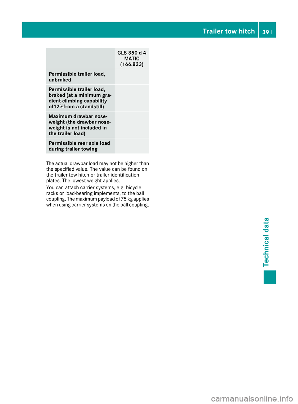
GLS 350 d 4
MATIC
(166.823) Permissible trailer load,
unbraked
Permissible trailer load,
braked (at a minimum gra-
dient-climbing capability
of12%from a standstill)
Maximum drawbar nose-
weight (the drawbar nose-
weight is not included in
the trailer load)
Permissible rear axle load
during trailer towing
The actual drawbar load may not be higher than
the specified value. The value can be found on
the trailer tow hitch or trailer identification
plates. The lowest weight applies.
You can attach carrier systems, e.g. bicycle
racks or load-bearing implements, to the ball
coupling. The maximum payload of 75 kg applies
when using carrier systems on the ball coupling. Trailer tow hitch
391Technical data Z