2016 MERCEDES-BENZ G-CLASS SUV tow
[x] Cancel search: towPage 234 of 261

X
When the vehicle is stationary, depress the
brake pedal and keep it depressed.
X Shift the transfer case to position Neutral
(Y page 125).
X Shift the automatic transmission to position
N.
X Leave the key in position 2in the ignition
lock.
X Release the brake pedal.
X Release the parking brake.
X Switc hont he hazard warning lamps
(Y page 76).
In order to signal achange of direction when
towing the vehicle with the hazard warning
lamps switched on, use the combination switch
as usual. In this case, only the turn signals for
the desired direction flash. When you reset the
combination switch, the hazard warning lamps
start flashing again.
i The automatic transmission can only
change gear when the batter yhas sufficient
charge.
If you cannot shift the automatic transmission
to position N,the propeller shafts to the
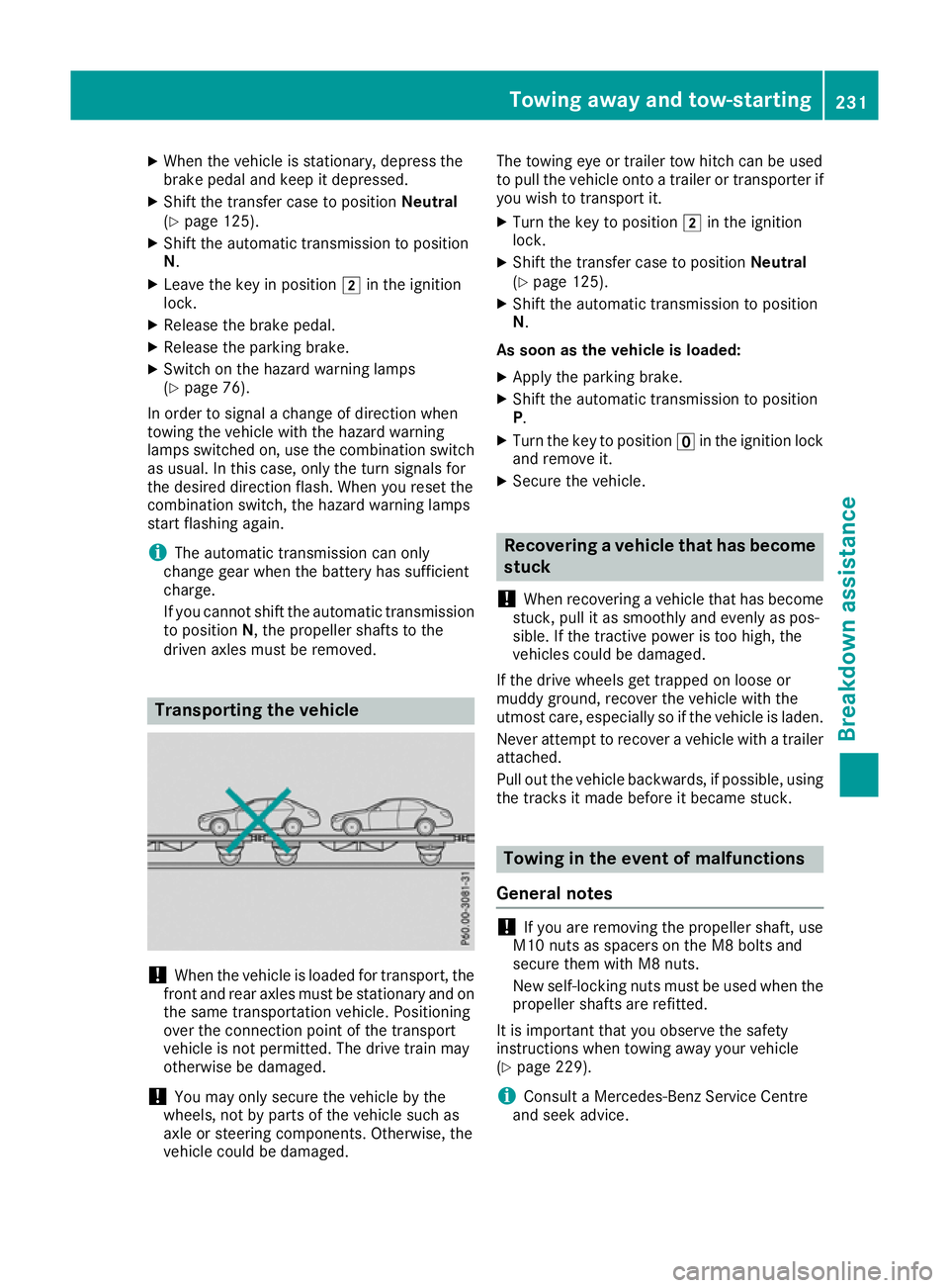
driven axles must be removed. Transporting thev
ehicle !
Whe
nthe vehicle is loadedf or transport, the
front and rear axles must be stationary and on the same transportation vehicle. Positioning
over the connection point of the transport
vehicle is not permitted. The drive train may
otherwise be damaged.
! You may only secure the vehicle by the
wheels, not by parts of the vehicle such as
axle or steering components. Otherwise, the
vehicle could be damaged. The towing eye or trailer tow hitch can be used
to pull the vehicle onto
atrailer or transporter if
you wish to transport it.
X Turn the key to position 2in the ignition
lock.
X Shift the transfer case to position Neutral
(Y page 125).
X Shift the automatic transmission to position
N.
As soon as the vehicle is loaded:
X Apply the parking brake.
X Shift the automatic transmission to position
P.
X Turn the key to position uin the ignition lock
and remove it.
X Secure the vehicle. Recovering
avehicle that has become
stuck
! Whe
nrecovering avehicl ethat ha sbecome
stuck, pull it as smoothly and evenly as pos-
sible .Ifthe tractive power is too high, the
vehicles could be damaged.
If the drive wheel sget trapped on loose or
muddy ground ,recover the vehicl ewitht he
utmost care ,especially so if the vehicl eisladen.
Neve rattempt to recover avehicl ewithat railer
attached.
Pull ou tthe vehicl ebackwards ,ifpossible ,using
the tracks it mad ebefore it became stuck. Towin
ginthe even tofm alfunctions
General notes !
If you are removing the propelle
rshaft, use
M10 nuts as spacers on the M8 bolts and
secure them with M8 nuts.
New self-locking nuts must be used when the propellers hafts are refitted.
It is important that you observe the safety
instructionsw hen towing awayy our vehicle
(Y page 229).
i Consult
aMercedes-Benz Service Centre
and seek advice. To
wing away and tow-starting
231Breakdown assis tance Z
Page 235 of 261

In th
eevent of damage to th eengine,
transmission or electrical system X
Shift th etransfer cas etoneutral position
Neutral (Ypage 125).
X Shif tthe automatic transmissio ntoposition
N.
In the even tofdamage to the transfer
case Have the propeller shafts between the axles and
the transfe rcase removed.
In the event of damage to the front axle Have the propeller shaft between the rea
raxle
and the transfe rcase removed.
The nhavet he vehicle towe dawayw itht he front
axl eraised.
In the event of damage to the rear axle Have the propeller shaft between the front axle
and the transfe rcase removed.
The nhavet he vehicle towe dwitht he rea raxle
raised and wheel rollers unde rthe front axle. Tow-start
ing( em ergency engine
starting)
! Do not tow-start vehicles with automatic
transmission. Yo ucould otherwis edamage
the automatic transmission.
Yo uc an find informatio non"Jump-starting"
under (Y page 227). Fuses
Importan
tsafety notes G
WARNING
If yo umanipulate, bridge or replace afaulty
fuse with afuse of ahigher amperage ,the
electric cables coul dbeoverloaded. This may
result in afire. There is arisk of an accident
and injury.
Always replace faulty fuses with specified new fuses of the correct amperage. The fuses in your vehicle disconnect fault
ycir-
cuits. If afuse blows, all the components in the
circuit and their functions will fail.
Blown fuses must be replaced with fuses of the same rating, which you can recognise by the
colour and fuse rating. The fuse ratings are listed
in the fuse allocation chart (Y page 233).
If the newly inserted fuse also blows, have the
cause traced and rectified at aqualified special-
ist workshop, e.g. aMercedes-Benz Service
Centre.
! Only use fuses that have been approved for
Mercedes-Benz vehicles and which have the
correc tfuse rating for the system concerned.
Otherwise, components or systems could be
damaged.
! Make sure that no moisture can enter the
fuse box when the cover is open.
! When closing the cover, make sure that it is
lying correctly on the fuse box. Moisture seep-
ing in or dirt could otherwise impair the oper-
ation of the fuses. Bef
orer eplacing afuse
Observ ethe important safety notes
(Y page 232).
X Switch off the engine.
X Switch off al lelectrical consumers.
X Remove the key from the ignition lock.
All indicator lamps on the instrument cluster
must be off.
X Secure the vehicl eagain st rolling away
(Y page 113).
The fuses are locate dinvarious fus eboxes:
R Main fus eboxon the front-passenger side of
the dashboard
R Fus eboxin the front-passenger footwell
R Fus eboxin the transmission tunnel
R Fus eboxin the luggage compartment
The fus ealloc ation chart and the spare fuses are
in the fus eboxon the dashboard on the front-
passenger side (Y page 233).
The fus eextractor is in the vehicl etool kit
(Y page 223). 232
FusesBreakdo
wn assis tance
Page 243 of 261

For further information on displaying this mes-
sage, refe rtothe "Checking the tyre pressure
electronically" section (Y page 240).
Important safety notes It is the driver's responsibility to set the tyre
pressure to the recommended cold tyre pres-
sure suitable for the operating situation
(Y page 238). Note that the correc ttyre pres-
sure for the current operating situation must
first be learnt by the tyre pressure monitor. If a
substantial loss of pressure occurs, the warning threshold for the warning message is aligned to
the learnt reference values. Restart the tyre
pressure monitor after adjusting to the cold tyre pressure (Y page 241). The current pressures
are saved as new reference values. This ensures that awarning message appears only if the tyre
pressure drops significantly.
The tyre pressure monitor does not warn you of
an incorrectly set tyre pressure. Observe the
notes on the recommended tyre pressure
(Y page 238).
The tyre pressure monitor is not abletow arn
you of asudden loss of pressure, e.g. if the tyre
is penetrated by aforeign object. In this event,
bring the vehicle to ahalt by braking carefully.
Avoid abrupt steering manoeuvres.
The tyre pressure monitor has ayellow h
warning lamp on the instrument cluster for indi-
cating apressure loss or malfunction. Depend-
ing on how the warning lamp flashe sorlights up,
at yre pressure that is too low or amalfunction in
the tyre pressure monitor is indicated:
R if the h warning lamp is lit continuously,
the tyre pressure on one or more tyres is sig-
nificantly too low. The tyre pressure monitor
is not malfunctioning.
R if the h warning lamp flashe sfor around a
minute and then remains lit constantly, the
tyre pressure monitor is malfunctioning.
In addition to the hwarning lamp,am essage
appears in the multifunction display. Observe
the information on display messages
(Y page 150).
It may take up to ten minutes for amalfunction
of the tyre pressure monitor to be indicated .A
malfunction willbei ndicated by thehtyre
pressure warning lamp flashing for approx-
imatel yone minute and then remaining lit. When
the faulth as been rectified, the htyre pres-
sure warning lamp goes out after driving for a
few minutes. The tyre pressure values indicated by the on-
board computer may differ from those meas-
ured at
afilling station using apressure gauge.
The tyre pressures shown by the on-board com-
puter refer to those measured at sea level. At
high altitudes, the tyre pressure values indica-
ted by apressure gauge are higher than those
shown by the on-board computer. In this case,
do not reduce the tyre pressures.
The operation of the tyre pressure monitor can
be affected by interferenc efrom radio transmit-
ting equipment (e.g. cordless headphones, two- way radios) that may be being operated in or
near the vehicle.
Checking the tyrep ressureelectroni-
cally X
Make sure that the key is in position 2in the
ignition lock.
X Press the =or; button on the steering
wheel to select the Serv.
Serv. menu.
X Press the 9or: button to select
Tyre pressure
Tyre pressure.
X Press the abutton.
The multifunction display shows the current
tyre pressure of each wheel.
If the vehicle has been parked for over
20 minutes, the Tyre pressures will be Tyre pressures will be
displayed
displayed after a
after afew
fewminutes
minutes of
ofdriv‐
driv‐
ing
ing message appears.
After ateach-in period, the tyre pressure moni-
tor automaticallyd etects new wheels or new
sensors. As long as aclear allocation of the tyre
pressure valuestot he individual wheels is not
possible,t heTyre
Tyre pressure
pressure monitor
monitoractive
active
displaym essage is shown instead of the tyre
pressure display. The tyre pressures are already being monitored.
If as pare wheel is fitted, the system may con-
tinue to show the tyre pressure of the wheel that has been removed for afew minutes. Please
note that in this case, the value displayed for the
replaced wheel does not indicate the current
tyre pressure of the spare wheel.
Warning messages of the tyre pressure monitor If the tyre pressure monitor detects
apressure
loss in one or more tyres, awarning messag eis
shown on the multifunction display. The yellow
h tyre pressure warning lamp then lights up. 240
Tyre pressureWheels and tyres
Page 249 of 261

for Mercedes-Benz vehicles and the respective
wheel.
X Clean the whee land whee lhub contact sur-
faces.
X Place the new whee lonthe whee lhub and
pus hito n.
X Tighten the whee lbolts until they are finger-
tight.
Lowering the vehicle G
WARNING
The wheels coul dwork loos eifthe whee lnuts
and bolts are not tightened to the specified
tightening torque .There is arisk of accident.
Have the tightening torque immediately
checked at aqualified specialist workshop
after awhee lisc hanged.
X Slowl yopen the pressure release screw on
the jack using the pump leve rbyapprox-
imatel yone full turn and carefully lower the
vehicl e(Ypage2 44).
X You can put the jack aside. X
Tighten the wheel bolts evenl yinacrosswise
pattern in the sequence indicated (: toA).
The specified tightening torque is 130 Nm.
X Dismantle the pump lever.
X Push the jack piston back in and close the
drain plug.
X Use the nuts to secure the faulty wheel to the
spare wheel bracket (Y page 223).
X Stow the jack and the vehicle tools in the
vehicle again.
X Check the tyre pressure of the newly fitted
wheel and adjust it if necessary.
Observe the recommended tyre pressure
(Y page 238). If you are drivin
gwith the emergency spare
wheel fitted, the tyre pressure monitor cannot
function reliably.R estart the tyre pressure mon-
itor only once the defective wheel has been
replaced with anew wheel.
All fitted wheelsm ust be equipped with func-
tioning sensors for the tyre pressure monitor. Wheel and tyre combinations
You can ask for information regarding permitted
wheel/tyre combinations at aMercedes-Benz
Service Centre.
! For safety reasons, Mercedes-Benz recom-
mends that you only use tyres, wheels and
accessories which have been approved by
Mercedes-Benz for you rvehicle. These are
speciall yadapted to the various driving safety
systems, such as ABS or ESP ®
.
Only use the tyres, wheels and accessories
tested and recommende dbyMercedes-Benz.
Certain characteristics, such as handling,
vehicl enoise emissions, fuel consumption,
etc. may otherwise be adversely affected.
Other wheel sizes may caus ethe tyres to
come into contact with the vehicl ebody and
axle components, whe nunder load. This may
result in damage to the tyre or the vehicle.
Mercedes-Benz is not responsibl efor any
damage caused by using tyres, wheels or
accessories other than those recommended.
Informatio nontyres, wheels and permissible
combinations can be obtained at aqualified
specialist workshop.
! Retreaded tyres are neither tested nor rec-
ommende dbyMercedes-Benz, since previ-
ous damage cannot alwaysbed etected on
retreaded tyres. As aresult, Mercedes-Benz
cannot guarantee vehicl esafety if retreaded
tyres are fitted. Do not fit use dtyres if you
have no information about their previous
usage.
! Large wheels: the lower the section width
for acertain wheel size, the lower the ride
comfort is on poor road surfaces. Rol lcomfort
and suspension comfort are reduced and the risk of damage to the wheels and tyres as a
result of driving over obstacles increases.
The recommende dtyre pressures for various
operating conditions can be found on the tyre 246
Wheel and tyre combinationsWheels and tyres
Page 252 of 261

nections intende
dfor us ewitht he basi cfittings.
Be sure to observe the manufacturer' saddi-
tional instructions when installing.
Deviations in respect of wavebands, maximum
transmission outputs or aeria lpositions must be
approved by Mercedes-Benz.
The maximu mtransmission outpu t(PE AK) at the
base of the aeria lmustn ot exceed the following
values: Waveband Maximum
transmissi on
output Short wave
3-54M
Hz 100 W
4mw
aveband
68 -87.5 MHz 30 W
2mw
aveband
144 -174 MHz 50 W
Trunked radio/Tetra
380
-460 MHz 10 W
70 cm waveband
400
-460 MHz 35 W
Mobilec
ommunications
(2G/3G/4G) 10 W
The following can be used in the vehicle without
restrictions:
R RF transmitters with amaximum transmis-
sion output of up to 100 mW
R RF transmitters with transmitter frequencies
in the 380 –410 MHz waveband and amaxi-
mum transmission output of up to 2W
(trunked radio/Tetra)
R Mobile phones (2G/3G/4G)
There are no restriction swhen positionin gthe
aerial on the outside of the vehicle for the fol-
lowing wavebands:
R Trunked radio/Tetra
R 70 cm waveband
R 2G/3G/4G Identification plates
Veh
icle identificatio nplate with vehi-
cl ei dentificatio nnumber (VIN) X
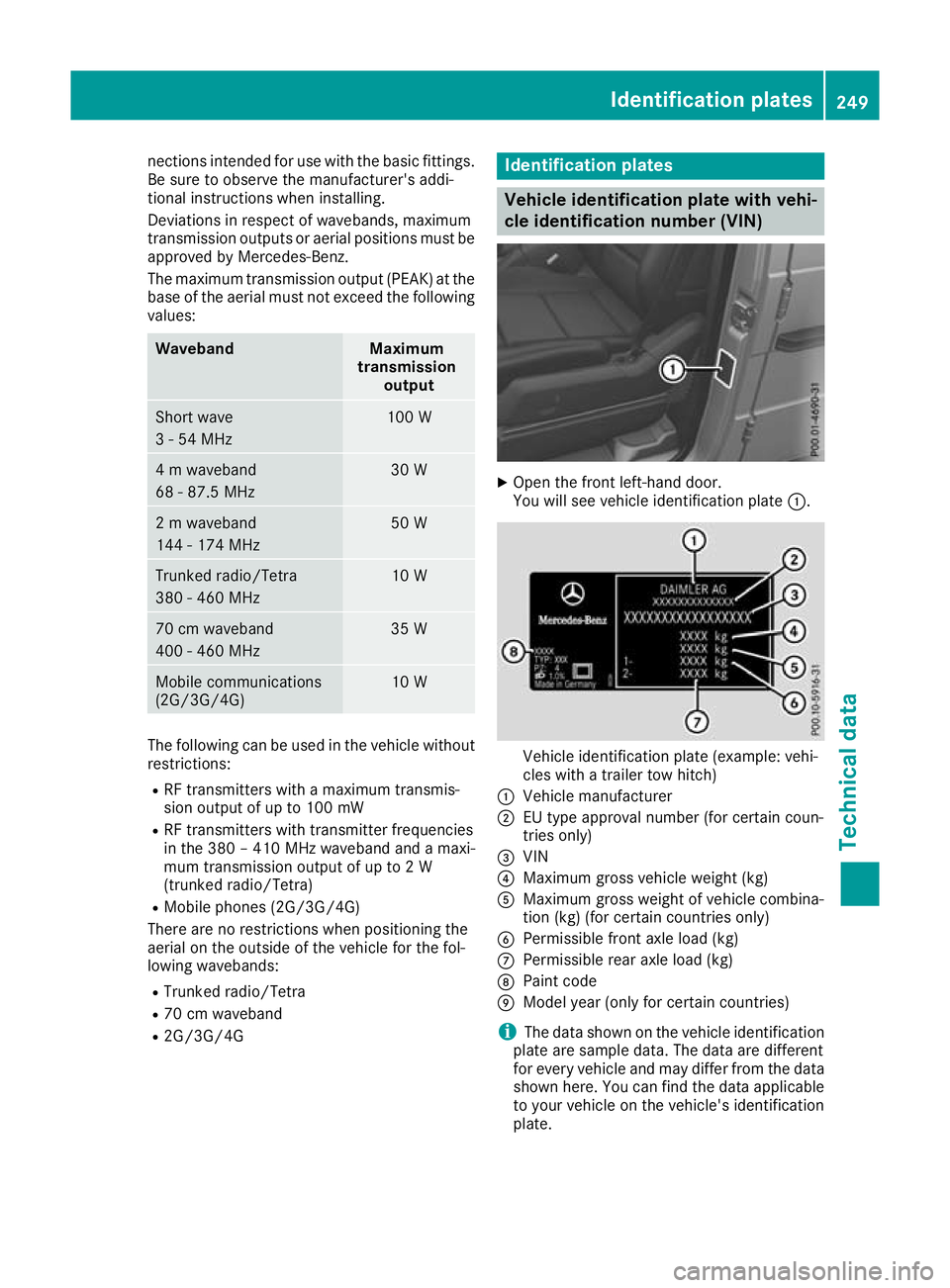
Ope nthe front left-hand door.
You will see vehicle identification plate :. Vehicle identification plate (example: vehi-
cles with
atrailer tow hitch)
: Vehicle manufacturer
; EU type approvaln umber (for certain coun-
tries only)
= VIN
? Maximum gross vehicle weight( kg)
A Maximum gross weightofv ehicle combina-
tion (kg) (for certain countries only)
B Permissiblef ront axle load (kg)
C Permissibler ear axle load (kg)
D Paint code
E Model year( only for certain countries)
i The data shown on the vehicle identification
plate are sample data. The data are different
for every vehicle and may differ from the data shown here. You can find the data applicable
to yourv ehicle on the vehicle's identification
plate. Identification plates
249Technical data Z
Page 259 of 261

Carefully depress th
eaccelerato rpedal and
mak esure that th ewheel sdon otspin when
driving on steep terrain.
i If th
eload on th efront axle is reduced when
pullin gaway on asteep uphill slope, th efront
wheel shave atendenc ytos pin .4ETSr ecog-
nises this and brakes th ewheel saccordingly.
The rear wheel torque is increased and it is
easie rtop ull away.
Further informatio nonthemaximum gradient
climbin gabilit y(Ypage 122). Trailer to
whitch Permissible trailer load, braked (at a
minimu mgradient-climbing capabil-
ity of 12% from astandstill) Model
G3
50dPROFES-
SIONAL 3200 kg
Permissible trailer load, unbraked
Model
G3
50dPROFES-
SIONAL 750 kg
Maximum drawbar load
! Use
adrawbar noseweight as close as pos-
sibl etot he maximu mpermissible nose-
weight. Do not use anoseweight of less than
50kg, otherwise the trailer may come loose.
Note that the payloada nd the rear axle load
are reduced by the actua lpayload.
The drawbar loadr educes the permissible over-
all loa dand rear axle load.
The drawbar loada cts from above onto the ball
hea dont he trailer tow hitch.
The drawbar loa disnot included in the trailer
load. Model Permissiblen
ose-
weight G3
50dPROFES-
SIONAL 140 kg You can secure carrier systems, e.g
.bicycle
rack sorl oad-bearing devices, to the ball cou-
pling. The maximum payload of 75 kg applies
when carrier systems are attached to the ball
coupling. Permissible rear axle load during
trailer towing
Model Permissibl
eaxle
load G3
50dPROFES-
SIONAL 1900 kg256
Trailer tow hitchTechnical data