Page 57 of 216

56
SAFETY
STARTING
AND DRIVING
WARNING
LIGHTS AND
MESSAGES
IN AN
EMERGENCY
SERVICE
AND CARE
TECHNICAL
SPECIFICATIONS
INDEX
CONTROLS
AND DEVICES
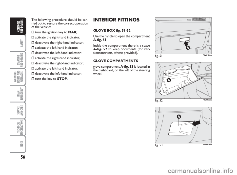
fig. 52F0M0077m
fig. 51F0M0104m
fig. 53F0M0078m
INTERIOR FITTINGS
GLOVE BOX fig. 51-52
Use the handle to open the compartment
A-fig. 51.
Inside the compartment there is a space
A-fig. 52to keep documents (for ver-
sions/markets, where provided).
GLOVE COMPARTMENTS
glove compartment A-fig. 53is located in
the dashboard, on the left of the steering
wheel. The following procedure should be car-
ried out to restore the correct operation
of the vehicle:❒turn the ignition key to MAR;
❒activate the right-hand indicator;
❒deactivate the right-hand indicator;
❒activate the left-hand indicator;
❒deactivate the left-hand indicator;
❒activate the right-hand indicator;
❒deactivate the right-hand indicator;
❒activate the left-hand indicator;
❒deactivate the left-hand indicator;
❒turn the key to STOP.
033-071 ACTUAL 1ed EN 21-07-2010 14:25 Pagina 56
Page 58 of 216
57
SAFETY
STARTING
AND DRIVING
WARNING
LIGHTS AND
MESSAGES
IN AN
EMERGENCY
SERVICE
AND CARE
TECHNICAL
SPECIFICATIONS
INDEX
CONTROLS
AND DEVICES
DOOR POCKETS fig. 56
There are document/map pockets locat-
ed in each of the door panels.FRONT ARMREST WITH
GLOVE COMPARTMENT
(for versions/markets, where provided)
Certain versions are fitted with an arm-
rest A-fig. 67between the front seats.
To use it as an armrest, push it down as
shown in fig. 57.
Press button A-fig. 58to raise the upper
part of the arm and access compartment
B. Operate lever Cto lower the angle
of the armrest.
fig. 54F0M0079m
fig. 55F0M0080mfig. 57F0M0225m
fig. 58F0M0245mfig. 56F0M0081m
Glove compartment B-fig. 54is located
in the middle of the dashboard.
Glove compartment Bcan be removed to
install a sound system.
CENTRAL CONSOLE GLOVE
COMPARTMENT
Compartment A-fig. 55is located on the
central console in front of the handbrake.
033-071 ACTUAL 1ed EN 21-07-2010 14:25 Pagina 57
Page 59 of 216

58
SAFETY
STARTING
AND DRIVING
WARNING
LIGHTS AND
MESSAGES
IN AN
EMERGENCY
SERVICE
AND CARE
TECHNICAL
SPECIFICATIONS
INDEX
CONTROLS
AND DEVICES
CIGARETTE LIGHTER fig. 62
This is located on the central console in
front of the handbrake.
Press button Ato activate the cigarette
lighter with ignition key at MAR.
After about 15 seconds the button will
return to its original position and the cig-
arette lighter is ready for use.
IMPORTANT Always check that the cig-
arette lighter has turned itself off.
fig. 62F0M0084m
The cigarette lighter gets
very hot. Handle it carefully
and make sure children don’t touch
it: risk of fire and/or burning.
WARNING
CUP HOLDERS – CAN HOLDERS
fig. 59-60
There are two cup/can holders in front of
the handbrake and one behind it on the
central console. CARD HOLDER – CD HOLDER
fig. 61
The central console features slots for te -
lephone cards CDs, magnetic cards or
motorway toll tickets.
fig. 59F0M0082mfig. 61F0M0083m
fig. 60F0M0118m
033-071 ACTUAL 1ed EN 21-07-2010 14:25 Pagina 58
Page 60 of 216

59
SAFETY
STARTING
AND DRIVING
WARNING
LIGHTS AND
MESSAGES
IN AN
EMERGENCY
SERVICE
AND CARE
TECHNICAL
SPECIFICATIONS
INDEX
CONTROLS
AND DEVICES
ASHTRAY fig. 63-64
The ashtray is a removable plastic box that
can be fitted into the cup/can holders on
the central console.
IMPORTANT Do not use the ashtray as
a waste paper basket at the same time: fire
hazard.SUN VISORS fig. 65
These are located at the sides of the rear
view mirror. They may be positioned at
the front and to the side.
A mirror can be applied to the back of the
driver-side sun visor:
To use the mirror (for versions/markets,
where provided), on some versions you
need to open the sliding cover A.
fig. 63F0M0085mfig. 65F0M0086m
fig. 64F0M0116m
SOCKET
(for versions/markets, where provided)
This is located in the boot, on the left side
of the plastic support for the parcel shelf
fig. 66.
To use it, open cap A.
EXTINGUISHER fig. 66a
(for versions/markets, where provided)
The extinguisher is located on the left side
of the luggage compartment.
fig. 66F0M0249m
fig. 66aF0U0530m
033-071 ACTUAL 1ed EN 21-07-2010 14:25 Pagina 59
Page 61 of 216

60
SAFETY
STARTING
AND DRIVING
WARNING
LIGHTS AND
MESSAGES
IN AN
EMERGENCY
SERVICE
AND CARE
TECHNICAL
SPECIFICATIONS
INDEX
CONTROLS
AND DEVICES
SKY DOME SUNROOF
(for versions/markets, where provided)
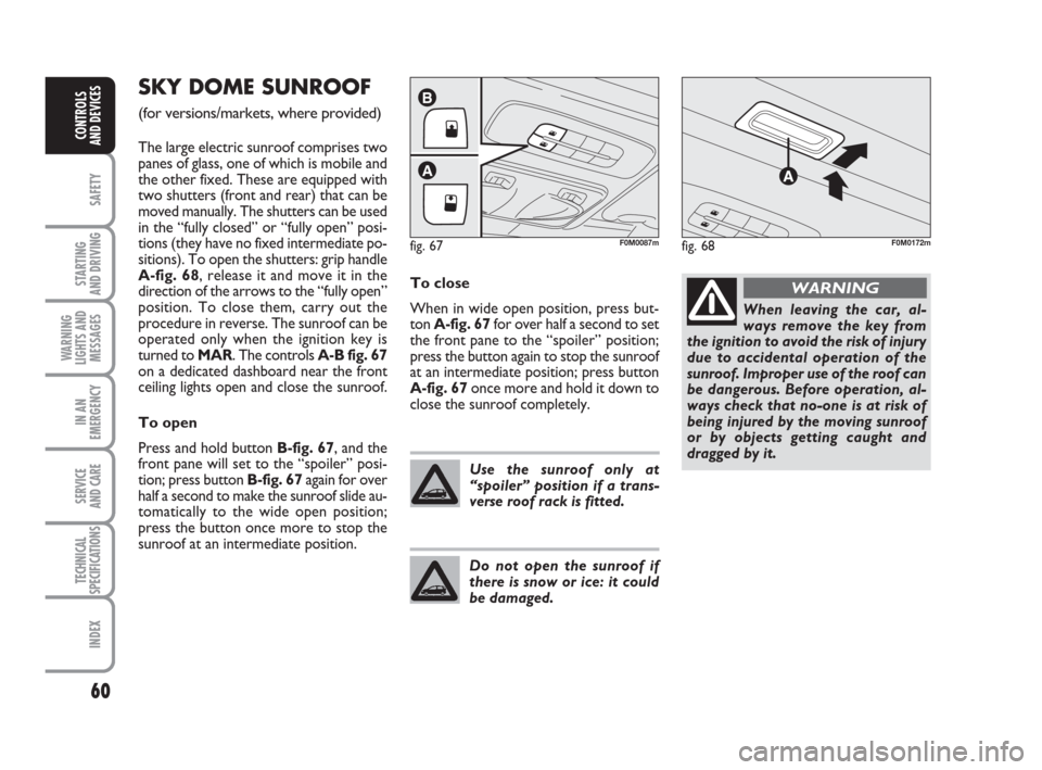
The large electric sunroof comprises two
panes of glass, one of which is mobile and
the other fixed. These are equipped with
two shutters (front and rear) that can be
moved manually. The shutters can be used
in the “fully closed” or “fully open” posi-
tions (they have no fixed intermediate po-
sitions). To open the shutters: grip handle
A-fig. 68, release it and move it in the
direction of the arrows to the “fully open”
position. To close them, carry out the
procedure in reverse. The sunroof can be
operated only when the ignition key is
turned to MAR. The controls A-B fig. 67
on a dedicated dashboard near the front
ceiling lights open and close the sunroof.
To open
Press and hold button B-fig. 67, and the
front pane will set to the “spoiler” posi-
tion; press button B-fig. 67 again for over
half a second to make the sunroof slide au-
tomatically to the wide open position;
press the button once more to stop the
sunroof at an intermediate position.To close
When in wide open position, press but-
ton A-fig. 67for over half a second to set
the front pane to the “spoiler” position;
press the button again to stop the sunroof
at an intermediate position; press button
A-fig. 67once more and hold it down to
close the sunroof completely.
fig. 67
A
B
F0M0087m
Use the sunroof only at
“spoiler” position if a trans-
verse roof rack is fitted.
Do not open the sunroof if
there is snow or ice: it could
be damaged.
When leaving the car, al-
ways remove the key from
the ignition to avoid the risk of injury
due to accidental operation of the
sunroof. Improper use of the roof can
be dangerous. Before operation, al-
ways check that no-one is at risk of
being injured by the moving sunroof
or by objects getting caught and
dragged by it.
WARNING
fig. 68F0M0172m
033-071 ACTUAL 1ed EN 21-07-2010 14:25 Pagina 60
Page 62 of 216

61
SAFETY
STARTING
AND DRIVING
WARNING
LIGHTS AND
MESSAGES
IN AN
EMERGENCY
SERVICE
AND CARE
TECHNICAL
SPECIFICATIONS
INDEX
CONTROLS
AND DEVICES
ANTI-PINCH SAFETY SYSTEM
The sunroof has an anti-pinch safety sys-
tem capable of detecting the presence of
an obstacle whilst the roof is closing; when
this happens, the system stops and the
movement of the glass is immediately re-
versed.INITIALISATION PROCEDURE
The sunroof must be re-initialised after
disconnecting the battery or if the rele-
vant protection fuse is blown.
Proceed as follows:
❒press button A-fig. 67at close posi-
tion;
❒hold the button down so that the sun-
roof closes in stages;
❒after full closing, wait for sunroof’s elec-
tric motor to stop.
When leaving the car, always remove the
key from the ignition to avoid the risk of
injury due to accidental operation of the
sunroof. Improper use of the roof can be
dangerous. Before and during operation,
always check that no-one is exposed to
the risk of being injured by the moving
sunroof or by objects getting caught and
dragged by it.EMERGENCY OPERATION
If the switch fails, the sun roof can be
moved manually as follows:
❒remove the protection cap located
between the two shutters;
❒take the Allen key (provided as stan-
dard) from the toolbox in the boot;
❒insert the key into hole A-fig. 69and
turn it:
– clockwise to open the roof;
– anticlockwise to close the roof.
fig. 69F0M0088m
033-071 ACTUAL 1ed EN 18-01-2011 11:49 Pagina 61
Page 63 of 216

62
SAFETY
STARTING
AND DRIVING
WARNING
LIGHTS AND
MESSAGES
IN AN
EMERGENCY
SERVICE
AND CARE
TECHNICAL
SPECIFICATIONS
INDEX
CONTROLS
AND DEVICES
DOORS
CENTRAL DOOR LOCKING/
UNLOCKING SYSTEM
LOCKING FROM THE OUTSIDE
With the doors closed, press button
Áon
the remote control fig. 70or insert the
key into the lock of the door on the dri-
ver’s side and turn it clockwise. Locking is
signalled by the LED on button A-fig. 72
coming on. The doors will be locked on-
ly if all doors are shut. If one or more
doors are open after pressing button
Áon
the remote control fig. 70, the direction
indicators and the LED on button A-fig.
72flash quickly for approximately 3 sec-
onds.
If one or more doors are open after turn-
ing the key, only the LED on button A-fig.
72will blink rapidly for approximately
three seconds. If the doors are closed but
the boot is open, the doors are locked:
the direction indicators (only when lock-
ing is carried out using button
Áfig. 70)
and the LED on button A-fig. 72flash
quickly for approximately 3 seconds.
With this function active, it is however
possible to unlock the other doors by
pressing button A-fig. 72on the central
panel.Quickly pressing button
Áon the remote
control fig. 70 twice will engage the dead
lock device (see paragraph “Dead lock
device”).
Door unlocking from the outside
Briefly press button
Ëfig. 70to unlock
the doors remotely, turn on the ceiling
lights for a limited period and double flash
the direction indicators, or insert the key
into the driver’s door lock and turn it an-
ti-clockwise as shown in fig. 71.
fig. 72F0M0075m
Door locking/unlocking
from the inside
Press button A-fig. 72to lock/unlock all
doors. The button has an LED that indi-
cates whether the doors are locked or un-
locked. When the doors are locked, the
LED is on and pressing the button brings
about central unlocking of all the doors and
turns off the LED. When the doors are un-
locked, the LED is off and pressing the but-
ton brings about central locking of all the
doors. The doors will be locked only if all
the doors are properly shut.
fig. 71F0M0410m
fig. 70F0M0409m
033-071 ACTUAL 1ed EN 21-07-2010 14:26 Pagina 62
Page 64 of 216

63
SAFETY
STARTING
AND DRIVING
WARNING
LIGHTS AND
MESSAGES
IN AN
EMERGENCY
SERVICE
AND CARE
TECHNICAL
SPECIFICATIONS
INDEX
CONTROLS
AND DEVICES
Following the locking of the doors using:
❒remote control;
❒door catch;
it will not be possible to unlock them by
pressing button
A-fig. 72located on the
dashboard.
IMPORTANT With central locking on,
pulling the internal handle of one of the
front doors will unlock that door. Indi-
vidual doors can be unlocked by pulling
the internal handle of one of the rear
doors.
If a power supply is not present (blown
fuse, battery disconnected, etc.) it is, how-
ever, possible to lock the doors manually.
After exceeding a speed of 20 km/h, all
doors will be centrally locked automati-
cally if the setup menu function has been
selected (see paragraph “Multifunction dis-
play” in this section).
Once the dead lock system is
engaged, it is impossible to
open the doors from inside the vehi-
cle. Before getting out of the car,
please therefore check that there is
no-one left on board. If the remote
control battery is flat, the system can
be disengaged only by inserting the
key in either of the door locks as de-
scribed previously: in this case the de-
vice remains active only for the rear
doors. DEAD LOCK
(for versions/markets, where provided)
This safety device inhibits the operation of:
❒interior handles;
❒locking/unlocking button A-fig. 72;
thereby preventing the opening of the
doors from inside the passenger com-
partment if there has been a break-in at-
tempt (e.g. a window has been broken).
The dead lock device therefore offers the
best possible protection against break-in
attempts. We recommend engaging it
whenever the vehicle is parked and left un-
attended.Device activation
The dead lock device is automatically ac-
tivated on every door by briefly pressing
the remote control button
Áfig. 70twice.
Device activation is indicated by 3 flashes
of the direction indicators and a flash of
the LED on button
A-fig. 72on the dash-
board.
If one or more of the doors is not closed
correctly, the dead lock device will not ac-
tivate, thus preventing a person from get-
ting stuck inside the passenger compart-
ment by entering the car through, and
then closing, the open door.
Device deactivation
The system is disabled automatically on
every door in the following cases:
❒when opening the driver’s door using
the key without remote control;
❒when unlocking doors using the remote
control;
❒when turning the ignition key to MAR.
WARNING
033-071 ACTUAL 1ed EN 21-07-2010 14:26 Pagina 63