2016 BMW M4 light
[x] Cancel search: lightPage 126 of 228
Deactivating MDMPress the button.
Indicator lights MDM and DSC OFF no
longer illuminate.
Via M DriveOn the Control Display:1."Settings"2."M Drive 1" or "M Drive 2"3. Select the symbol.4."MDM"
To call up the desired M Drive with the selec‐
ted settings, press the corresponding button
on the steering wheel:
▷▷
A message appears in the instrument cluster.
This message is operated by pressing the but‐
ton again.
Deactivating MDM
Press the corresponding button 1 or button 2
on the steering wheel again.
M Dynamic Mode and the settings selected
under M Drive are deactivated.
Indicator and warning lights Indicator lights illuminate:
M Dynamic Mode is activated.
DSC indicator light also flashes:
M Dynamic Mode is regulating the driv‐
ing and braking forces.
Indicator lights illuminate:
M Dynamic Mode or DSC has failed.
Active M Differential
Principle The active M Differential blocks the rear axis
transmission steplessly, depending on the
drive situation. In so doing, even with the DSC
switched off and in M Dynamic Mode, spinning
of a single rear wheel is avoided and therefore
optimum traction is provided under all driving
conditions.
The driver is responsible for a driving style ap‐
propriate to the situation.
Adaptive M chassis PrincipleThe system reduces unwanted vehicle move‐
ments when a dynamic driving style is used or
on uneven roads.
Depending on the condition of the road and
the driving style, this enhances driving dynam‐
ics and driving comfort.
Programs Possibilities for adjusting the tuning of the
shock absorbers:▷"Comfort": comfort-oriented▷"Sport": balanced▷"Sport Plus": consistently sporty
Selecting program
Via M Drive
1."Settings"2."M Drive 1" or "M Drive 2"3. Select the symbol.4.Select the desired channel.Seite 126ControlsDriving stability control systems126
Online Edition for Part no. 01 40 2 964 013 - VI/15
Page 127 of 228
Setting is immediately accepted with ac‐
tive M Drive.
To activate the desired M Drive with the selec‐
ted settings, press the corresponding button
on the steering wheel:
▷▷
Using the button
Press button until the desired program is
displayed in the instrument cluster.
Display in the instrument cluster Adaptive M chassis with selected pro‐
gram and activated display of driving
dynamics system statuses, see
page 86.
Drive-off assistant The system provides support when driving off
on upward inclines. It is not necessary to use
the parking brake for this.
1.Hold the vehicle in place by pressing the
foot brake.2.Release the foot brake and drive off with‐
out delay.
The vehicle is held for approximately 2 sec‐
onds after the foot brake has been released.
Depending on the vehicle's load or when tow‐
ing a trailer, the vehicle may roll backwards a
little.
Servotronic
Principle The Servotronic varies the steering force re‐
quired when steering, depending on the
speed. At low speeds the steering force is
heavily supported, in other words a slight force
is needed when steering With increasing
speed the support for the steering force is re‐
duced.
In addition, steering force is adapted according
to drive program, giving a sporty/direct or com‐
fortable steering response.
Programs Adjustment possibilities of the steering force:▷"Comfort": low.▷"Sport": medium.▷"Sport Plus": high.
Selecting program
Via M Drive On the Control Display:
1."Settings"2."M Drive 1" or "M Drive 2"3. Select the symbol.4.Select the desired channel.
Setting is immediately accepted with ac‐
tive M Drive.
To activate the desired M Drive with the selec‐
ted settings, press the corresponding button
on the steering wheel:
▷▷Seite 127Driving stability control systemsControls127
Online Edition for Part no. 01 40 2 964 013 - VI/15
Page 130 of 228
▷When interrupted: press once.
The indicators turn off. The saved desired
speed is deleted.
Interrupting When the system is activated, press
the button on the steering wheel.
The system interrupts automatically in the
following situations:
▷If the brake is applied.▷If the clutch is depressed for a few seconds
or released with no gear engaged.▷If too high a gear has been engaged for the
speed.▷If MDM is activated or DSC is deactivated.▷If DSC intervenes.
Maintaining, saving, changing speed
Notes WARNING
The desired speed can be inadvertently
set incorrectly or called up. Danger of acci‐
dents. Adapt the desired speed to the driving
conditions. Observe the traffic situation and in‐
tervene actively if the situation warrants it.◀
Maintaining speed, saving
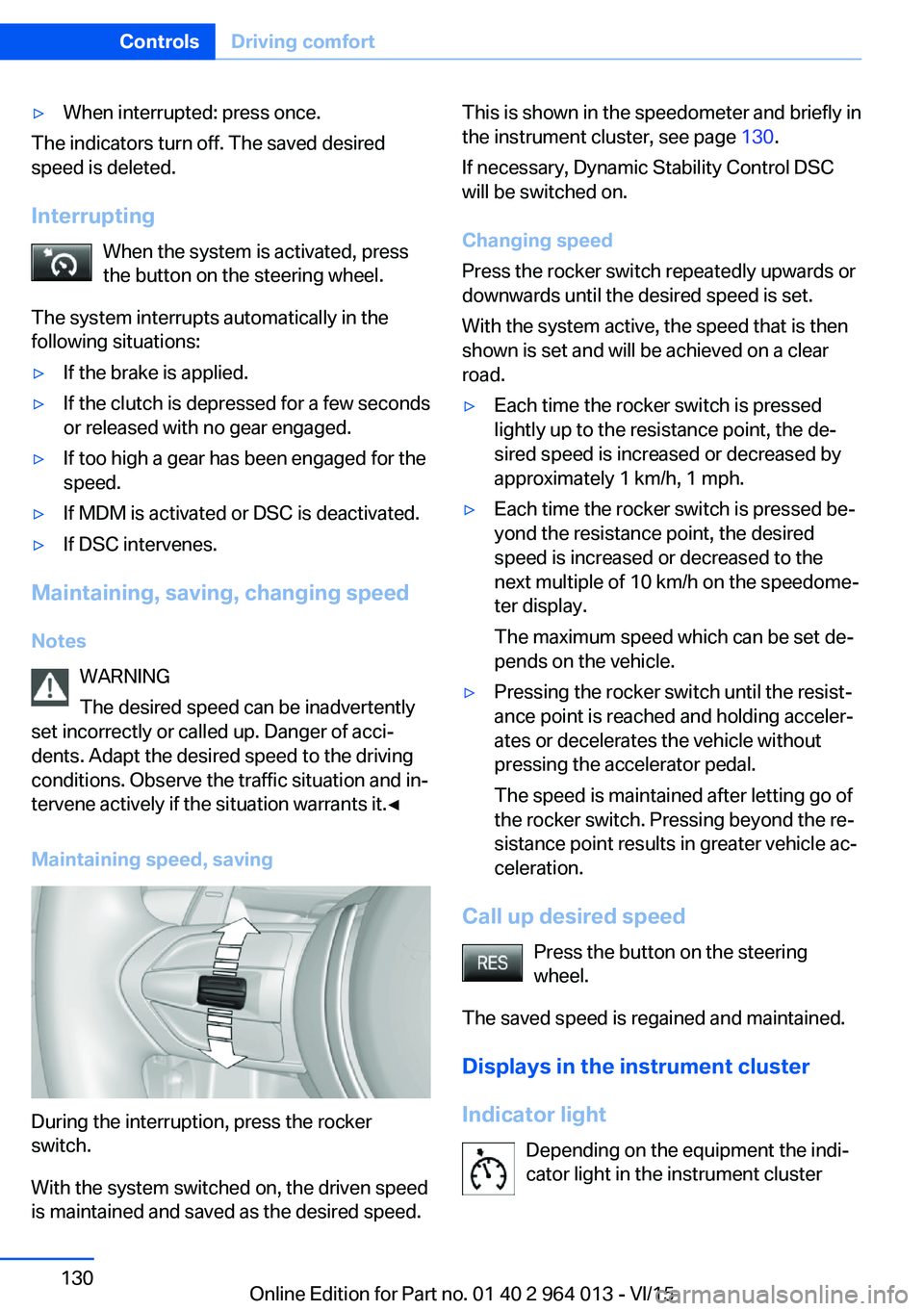
During the interruption, press the rocker
switch.
With the system switched on, the driven speed
is maintained and saved as the desired speed.
This is shown in the speedometer and briefly in
the instrument cluster, see page 130.
If necessary, Dynamic Stability Control DSC
will be switched on.
Changing speed
Press the rocker switch repeatedly upwards or
downwards until the desired speed is set.
With the system active, the speed that is then
shown is set and will be achieved on a clear
road.▷Each time the rocker switch is pressed
lightly up to the resistance point, the de‐
sired speed is increased or decreased by
approximately 1 km/h, 1 mph.▷Each time the rocker switch is pressed be‐
yond the resistance point, the desired
speed is increased or decreased to the
next multiple of 10 km/h on the speedome‐
ter display.
The maximum speed which can be set de‐
pends on the vehicle.▷Pressing the rocker switch until the resist‐
ance point is reached and holding acceler‐
ates or decelerates the vehicle without
pressing the accelerator pedal.
The speed is maintained after letting go of
the rocker switch. Pressing beyond the re‐
sistance point results in greater vehicle ac‐
celeration.
Call up desired speed
Press the button on the steering
wheel.
The saved speed is regained and maintained.
Displays in the instrument cluster
Indicator light Depending on the equipment the indi‐
cator light in the instrument cluster
Seite 130ControlsDriving comfort130
Online Edition for Part no. 01 40 2 964 013 - VI/15
Page 133 of 228

▷With persons with certain clothing, for ex‐
ample a coat.▷With external disruption to the ultrasound,
for example by passing vehicles or loud
machines.▷If the sensors are dirty, iced-up, damaged
or incorrectly adjusted.▷In certain weather conditions, for example
high humidity, rain, snowfall, extreme heat
or strong wind.▷With trailer noses and tow hitches of other
vehicles.▷With thin or wedge-shaped objects.▷With moving objects.▷For higher, protruding objects, for example
projecting walls or loads.▷For objects with corners and sharp edges.▷For objects with fine surfaces or struc‐
tures, for example fences.▷For objects with porous surfaces.
Low objects already indicated, such as kerbs,
may enter the sensors' blind areas before or
after a continuous tone is given.
False alarms
Under the following conditions, PDC can issue
a warning although there is no obstacle in the
detection range:
▷In heavy rain.▷If the sensors are very dirty or covered with
ice.▷If the sensors are covered with snow.▷On rough road surfaces.▷On uneven ground, for example speed
bumps.▷In large, rectangular buildings with smooth
walls, for example underground car parks.▷In car washes.▷Due to dense exhaust gas.▷Due to other ultrasonic sources, for exam‐
ple sweeping machines, steam-jet cleaners
or neon lights.
The functional disruption is reported by an
alternating continuous tone between the
front and rear loudspeakers. As soon as
the disruption by other ultrasound sources
is no longer present, the system is fully
functional again.
Malfunction
A Check Control message is shown.
The recording area of the sensors is shown
hatched on the Control Display.
PDC has failed. Have the system checked.
Surround view Principle
Surround view contains various camera assis‐
tance systems, providing support when park‐
ing, manoeuvring and exits and junctions with
poor visibility.
▷Rear-view camera, see page 133.▷Side view, see page 136.▷Top view, see page 137.
Rear-view camera
Principle The rear-view camera offers assistance when
reversing into a parking space or manoeuvring.
To achieve this, the area behind the vehicle is
displayed on the Control Display.
Notes WARNING
The system does not take your personal
responsibility from you when you are estimat‐
ing the traffic situation. Danger of accidents.
Adapt driving style to the driving conditions.
Seite 133Driving comfortControls133
Online Edition for Part no. 01 40 2 964 013 - VI/15
Page 139 of 228

2.Turn the controller until the desired setting
is reached and press the controller.
Displaying the turning circle and
driving lane line
▷The static red turning circle line indicates
the space requirement to the side with full
steering angle.▷The variable green driving lane line helps to
estimate the actual space requirement to
the side.
The lane line depends on the engaged
gear and the current steering angle. The
lane line is continuously adjusted by the
steering wheel movement.
"Parking guidance lines"
The turning circle and driving lane lines are
displayed.
System limits
Top View cannot be used in the following sit‐
uations:
▷With a door open.▷With the boot lid open.▷With an exterior mirror folded in.▷In poor light conditions.
In some of these situations a Check Control
message is displayed.
Park Assistant
Principle
The system supports you when parking in par‐
allel to the road.
Ultrasonic sensors measure parking spaces on
both sides of the vehicle.
The park assistant calculates the ideal parking
line and takes over steering during the process
of parking.
When parking up, also follow the visual and au‐
dible information and notes of the PDC, the
Park Assistant and the rear-view camera, and
respond accordingly.
The park assistant incorporates Park Distance
Control, PDC, see page 131.
Notes WARNING
The system does not take your personal
responsibility from you when you are estimat‐
ing the traffic situation. Due to limits of the sys‐
tem, it cannot respond independently in a rea‐
sonable way in all traffic conditions. Danger of
accidents. Adapt driving style to the driving
conditions. Observe the traffic situation and in‐
tervene actively if the situation warrants it.◀
ATTENTION
The Park Assistant may steer across
curbs or up onto curbs. Danger of damage to
property. Observe the traffic situation and in‐
tervene actively if the situation warrants it.◀
An engine stopped by the Auto Start Stop
function is automatically started by activating
the Park Assistant.Seite 139Driving comfortControls139
Online Edition for Part no. 01 40 2 964 013 - VI/15
Page 141 of 228
Display on the Control Display
System is activated/deactivatedSymbolMeaning Grey: system not available.
White: system available but not ac‐
tivated. System is activated.
Status of the system
▷Coloured symbols, see arrows, on the side
of the vehicle display. Park Assistant is ac‐
tivated and parking space search is active.▷Suitable parking spaces are shown on the
Control Display on the edge of the roadway
next to the vehicle symbol. With active
Park Assistant, the suitable parking spaces
are highlighted in colour.▷Parking process active.
Steering has been taken
over.▷The parking space search is always active
with slow straight forward driving, even
with deactivated system. With deactivated
system, the displays on the Control Display
are shown grey.Status of the system▷Symbol P, see arrow, on the vehicle dis‐
play. Park Assistant is activated and park‐
ing space search is active.▷Suitable parking spaces are shown on the
Control Display on the edge of the roadway
next to the vehicle symbol. With active
Park Assistant, the suitable parking spaces
are highlighted in colour.▷When perpendicular or parallel parking
spaces are definitely detected, the system
automatically sets the appropriate parking
method. A selection menu is displayed for
parking spaces that are large enough for
both parallel and perpendicular parking. In
this case, select the desired parking
method manually.▷Parking process active.
Steering has been taken
over.▷The parking space search is always active
with slow straight forward driving, even
with deactivated system. With deactivated
system, the displays on the Control Display
are shown grey.
Parking with the Park Assistant
WARNING
The system does not take your personal
responsibility from you when you are estimat‐
ing the traffic situation. Danger of accidents.
Adapt driving style to the driving conditions.
Additionally, look directly to check the traffic
Seite 141Driving comfortControls141
Online Edition for Part no. 01 40 2 964 013 - VI/15
Page 149 of 228
Interior equipmentVehicle equipmentThis chapter describes all standard, national
and special equipment provided in the model
series. Equipment not available in the vehicle is
therefore also described, for example the se‐
lected special equipment or national version.
This also applies to safety-relevant functions
and systems. Comply with the relevant na‐
tional regulations when using the correspond‐
ing functions and systems.
Sun visor Glare protection Fold the sun visor downwards or upwards.
Vanity mirror
A vanity mirror is situated in the sun visor be‐
hind a cover. The mirror light switches on
when the cover is opened.
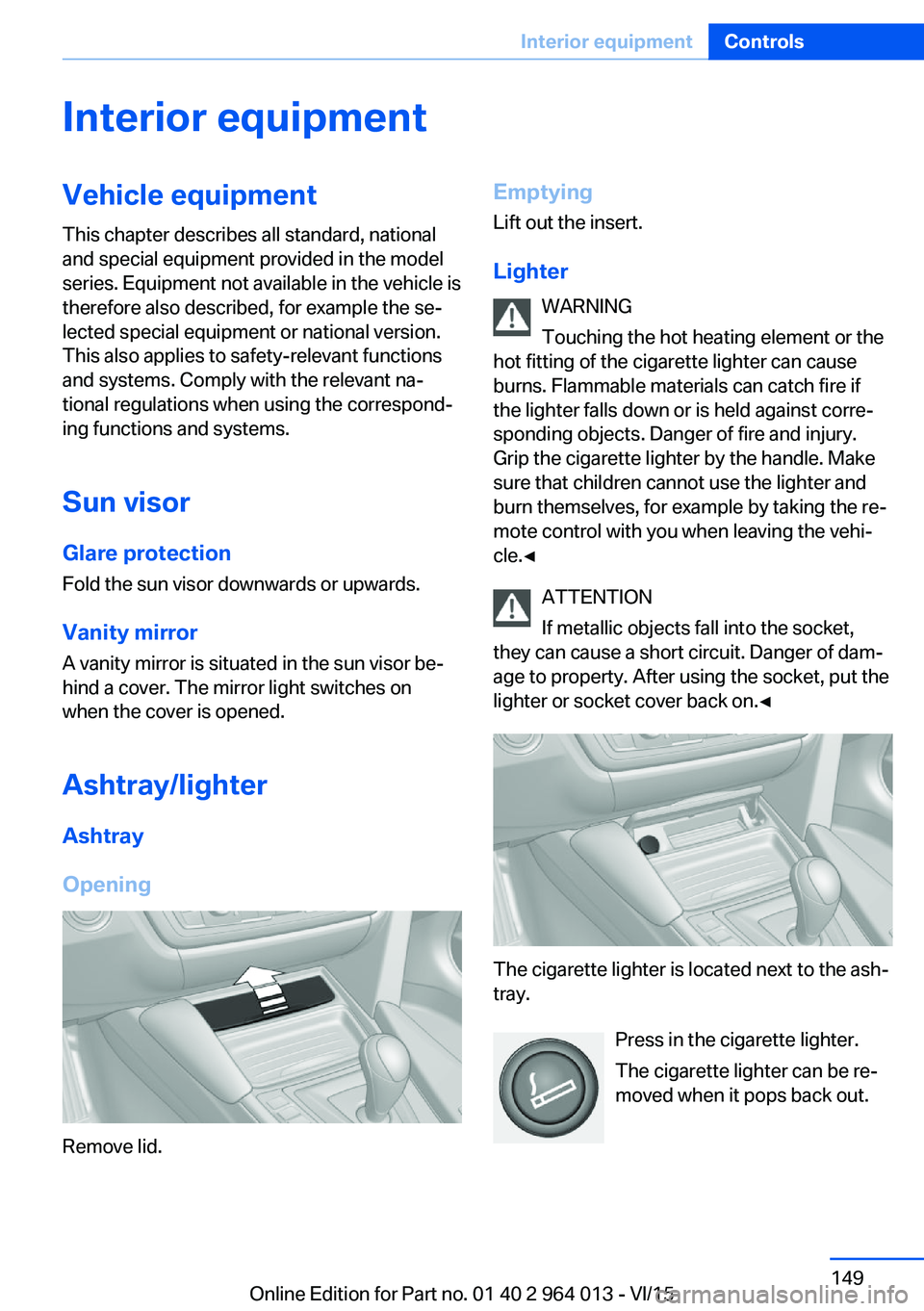
Ashtray/lighter Ashtray
Opening
Remove lid.
Emptying Lift out the insert.
Lighter WARNING
Touching the hot heating element or the
hot fitting of the cigarette lighter can cause
burns. Flammable materials can catch fire if
the lighter falls down or is held against corre‐
sponding objects. Danger of fire and injury.
Grip the cigarette lighter by the handle. Make
sure that children cannot use the lighter and
burn themselves, for example by taking the re‐ mote control with you when leaving the vehi‐
cle.◀
ATTENTION
If metallic objects fall into the socket,
they can cause a short circuit. Danger of dam‐
age to property. After using the socket, put the
lighter or socket cover back on.◀
The cigarette lighter is located next to the ash‐
tray.
Press in the cigarette lighter.
The cigarette lighter can be re‐
moved when it pops back out.
Seite 149Interior equipmentControls149
Online Edition for Part no. 01 40 2 964 013 - VI/15
Page 150 of 228
Connecting electrical
appliances
Information ATTENTION
Battery chargers for the vehicle battery
can operate with high voltages and high cur‐
rents, which can overload or damage the
12 volt on-board network. Danger of damage
to property. Only connect battery chargers for
the vehicle battery to the jump-starting con‐
nections in the engine compartment.◀
ATTENTION
If metallic objects fall into the socket,
they can cause a short circuit. Danger of dam‐
age to property. After using the socket, put the
lighter or socket cover back on.◀
Power sockets
General
Cigarette lighter socket can be used as a
socket for electrical devices when the engine
is running or the ignition is switched on.
Note The total load of all sockets must not exceed
140 Watt at 12 Volt.
To avoid damage to the socket, do not insert
an incompatible plug.
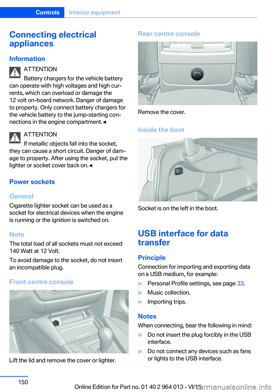
Front centre console
Lift the lid and remove the cover or lighter.
Rear centre console
Remove the cover.
Inside the boot
Socket is on the left in the boot.
USB interface for data
transfer
Principle Connection for importing and exporting data
on a USB medium, for example:
▷Personal Profile settings, see page 33.▷Music collection.▷Importing trips.
Notes
When connecting, bear the following in mind:
▷Do not insert the plug forcibly in the USB
interface.▷Do not connect any devices such as fans
or lights to the USB interface.Seite 150ControlsInterior equipment150
Online Edition for Part no. 01 40 2 964 013 - VI/15